ECU FIAT DOBLO COMBI 2010 Owner handbook (in English)
[x] Cancel search | Manufacturer: FIAT, Model Year: 2010, Model line: DOBLO COMBI, Model: FIAT DOBLO COMBI 2010Pages: 274, PDF Size: 6.16 MB
Page 117 of 274
116
KNOW
YOUR
VEHICLE
SAFETY
STARTING
AND
DRIVING
WARNING
LIGHTS AND
MESSAGES
IN AN
EMERGENCY
SERVICING
AND
MAINTENANCE
TECHNICAL
SPECIFICATIONS
INDEX
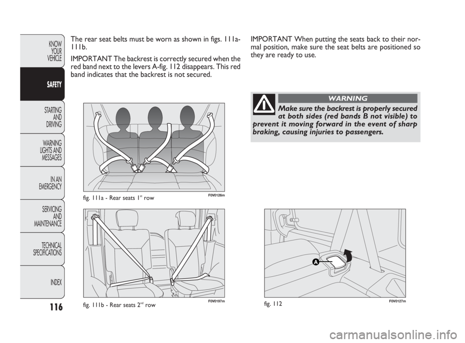
F0V0126mfig. 111a - Rear seats 1strow
F0V0127mfig. 112
The rear seat belts must be worn as shown in figs. 111a-
111b.
IMPORTANT The backrest is correctly secured when the
red band next to the levers A-fig. 112 disappears. This red
band indicates that the backrest is not secured.
Make sure the backrest is properly secured
at both sides (red bands B not visible) to
prevent it moving forward in the event of sharp
braking, causing injuries to passengers.
WARNING
IMPORTANT When putting the seats back to their nor-
mal position, make sure the seat belts are positioned so
they are ready to use.
F0V0197mfig. 111b - Rear seats 2ndrow
115-132 DOBLO LUM EN 2e 7.0 21-05-2010 11:11 Pagina 116
Page 121 of 274
120
KNOW
YOUR
VEHICLE
SAFETY
STARTING
AND
DRIVING
WARNING
LIGHTS AND
MESSAGES
IN AN
EMERGENCY
SERVICING
AND
MAINTENANCE
TECHNICAL
SPECIFICATIONS
INDEX
SEAT BELT MAINTENANCE
Observe the following precautions for correct seat belt
maintenance:
❒always make sure the belt is well stretched and never
twisted; make sure that it is free to run without ob-
structions;
❒replace the belt after a serious accident, even if it does
not appear damaged. Always replace the seat belt if the
pretensioners were deployed;
❒To clean the belt, wash by hand with water and mild
soap, rinse and leave to dry in the shade. Do not use
strong detergents, bleach, paints or any other chemi-
cals which could damage the belt fibres;
❒prevent the reels from getting wet: their correct op-
eration is guaranteed only if water does not get inside;
❒replace the seat belt if it shows significant signs of wear
and tear.
If the belt has been subjected to heavy
stress, for example after an accident, it
should be changed completely together with the
anchors, anchor fastening screws and the preten-
sioner. In fact, even if the belt has no visible de-
fects, it could have lost its resilience.
WARNINGCARRYING CHILDREN SAFELY
For optimum protection in the event of a crash, all pas-
sengers must be seated and wearing adequate restraint
systems.
This is even more important for children.
This prescription is compulsory in all EU countries ac-
cording to EC Directive 2003/20/EC.
Compared with an adult, a child’s head is larger and heav-
ier in proportion to his/her body and the child’s muscu-
lar and bone structures are not fully developed. For this
reason, they require restraint systems which are differ-
ent from those used by adults to protect them in the event
of an accident.
The result of research in relation to the best protection
for children is illustrated in European Regulation ECE-R44,
which divides the restraint systems into five groups in ad-
dition to making their use compulsory:
Group 0 up to 10 kg
Group 0+ up to 13 kg
Group 1 9-18 kg
Group 2 15-25 kg
Group 3 22-36 kg
As you can see, the groups overlap partly and, in fact, there
are devices on sale that cover more than one weight group.
All restraint devices must bear the type-approval data along
with the control mark on a label firmly secured to the child
seat which must never be removed.
115-132 DOBLO LUM EN 2e 7.0 21-05-2010 11:11 Pagina 120
Page 123 of 274
122
KNOW
YOUR
VEHICLE
SAFETY
STARTING
AND
DRIVING
WARNING
LIGHTS AND
MESSAGES
IN AN
EMERGENCY
SERVICING
AND
MAINTENANCE
TECHNICAL
SPECIFICATIONS
INDEX
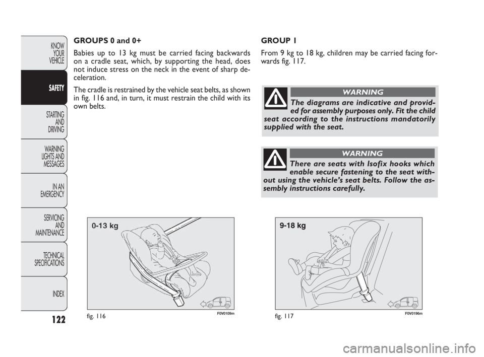
F0V0109mfig. 116F0V0196mfig. 117
GROUP 1
From 9 kg to 18 kg, children may be carried facing for-
wards fig. 117. GROUPS 0 and 0+
Babies up to 13 kg must be carried facing backwards
on a cradle seat, which, by supporting the head, does
not induce stress on the neck in the event of sharp de-
celeration.
The cradle is restrained by the vehicle seat belts, as shown
in fig. 116 and, in turn, it must restrain the child with its
own belts.
The diagrams are indicative and provid-
ed for assembly purposes only. Fit the child
seat according to the instructions mandatorily
supplied with the seat.
WARNING
There are seats with Isofix hooks which
enable secure fastening to the seat with-
out using the vehicle’s seat belts. Follow the as-
sembly instructions carefully.
WARNING
115-132 DOBLO LUM EN 2e 7.0 21-05-2010 11:11 Pagina 122
Page 127 of 274
126
KNOW
YOUR
VEHICLE
SAFETY
STARTING
AND
DRIVING
WARNING
LIGHTS AND
MESSAGES
IN AN
EMERGENCY
SERVICING
AND
MAINTENANCE
TECHNICAL
SPECIFICATIONS
INDEX
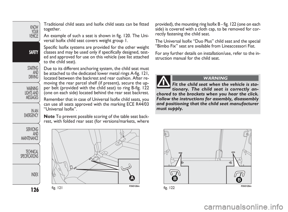
F0V0128mfig. 121F0V0129mfig. 122
Traditional child seats and Isofix child seats can be fitted
together.
An example of such a seat is shown in fig. 120. The Uni-
versal Isofix child seat covers weight group 1.
Specific Isofix systems are provided for the other weight
classes and may be used only if specifically designed, test-
ed and approved for use on this vehicle (see list attached
to the child seat).
Due to its different anchoring system, the child seat must
be attached to the dedicated lower metal rings A-fig. 121,
located between the backrest and rear cushion. After re-
moving the rear parcel shelf (if present), secure the up-
per belt (provided with the child seat) to ring B-fig. 122
(one on each side) located behind the rear seat backrest.
Remember that in case of Universal Isofix child seats, you
can use all seats approved with the marking ECE R44/03
“Universal Isofix”.
NoteTo prevent possible scoring of the table seat back-
rest, with folded rear seat (for versions/markets, whereprovided), the mounting ring Isofix B - fig. 122 (one on each
side) is covered with a cloth cap, to be removed for cor-
rectly fastening the child seat.
The Universal Isofix “Duo Plus” child seat and the special
“Bimbo Fix” seat are available from Lineaccessori Fiat.
For any further details on installation/use, refer to the in-
struction manual for the child seat.
Fit the child seat when the vehicle is sta-
tionary. The child seat is correctly an-
chored to the brackets when you hear the click.
Follow the instructions for assembly, disassembly
and positioning that the child seat manufacturer
must supply.
WARNING
115-132 DOBLO LUM EN 2e 7.0 21-05-2010 11:11 Pagina 126
Page 136 of 274
135
KNOW
YOUR
VEHICLE
SAFETY
STARTING
AND
DRIVING
WARNING
LIGHTS AND
MESSAGES
IN AN
EMERGENCY
SERVICING
AND
MAINTENANCE
TECHNICAL
SPECIFICATIONS
INDEX
HANDBRAKE
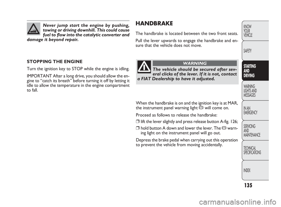
The handbrake is located between the two front seats.
Pull the lever upwards to engage the handbrake and en-
sure that the vehicle does not move.
STOPPING THE ENGINE
Turn the ignition key to STOP while the engine is idling.
IMPORTANT After a long drive, you should allow the en-
gine to “catch its breath” before turning it off by letting it
idle to allow the temperature in the engine compartment
to fall.
Never jump start the engine by pushing,
towing or driving downhill. This could cause
fuel to flow into the catalytic converter and
damage it beyond repair.
The vehicle should be secured after sev-
eral clicks of the lever. If it is not, contact
a FIAT Dealership to have it adjusted.
WARNING
When the handbrake is on and the ignition key is at MAR,
the instrument panel warning light
xwill come on.
Proceed as follows to release the handbrake:
❒lift the lever slightly and press release button A-fig. 126;
❒hold button A down and lower the lever. The xwarn-
ing light on the instrument panel will go out.
Depress the brake pedal when carrying out this operation
to prevent the vehicle from moving accidentally.
133-142 DOBLO LUM EN 2e 7.0 21-05-2010 11:12 Pagina 135
Page 158 of 274
157
KNOW
YOUR
VEHICLE
SAFETY
STARTING
AND
DRIVING
WARNING
LIGHTS AND
MESSAGES
IN AN
EMERGENCY
SERVICING
AND
MAINTENANCE
TECHNICAL
SPECIFICATIONS
INDEX
The spare wheel (where provided) is
specifically for your vehicle. Therefore, it
must not be used on other models. Do not use
spare wheels of other models on your vehicle. The
spare wheel should be used only in an emergency.
Use it as little as possible.
WARNING
Use your hazard lights, warning triangle,
etc to show that your car is stationary.
Passengers should get out of the car, particularly
if it is heavily loaded, and wait for the wheel to be
changed away from the traffic. If you are on a
steep slope or uneven surface, place wedges or
other suitable objects under the wheels to secure
the vehicle. Repair and refit the standard wheel
as soon as possible. Do not grease the bolt threads
before you fit them, because they could sudden-
ly come loose.
WARNING
Use the jack only to replace wheels on the
vehicle with which it is supplied or on oth-
er vehicles of the same model. Never use the jack
for other purposes, such as lifting other models.
Never use the jack to carry out repairs under the
vehicle. Incorrect positioning of the jack may
cause the lifted vehicle to fall. Do not use the jack
for loads higher than the one shown on its label.
WARNING
Incorrect hub cap assembly may cause it
to come off when the car is moving. Nev-
er tamper with the inflation valve. Never intro-
duce tools of any kind between the rim and the
tyre. Check tyre and spare wheel pressures regu-
larly, referring to the values shown in the “Tech-
nical specifications” section.
WARNING
155-190 DOBLO LUM EN 2e 7.0 21-05-2010 11:34 Pagina 157
Page 163 of 274
162
KNOW
YOUR
VEHICLE
SAFETY
STARTING
AND
DRIVING
WARNING
LIGHTS AND
MESSAGES
IN AN
EMERGENCY
SERVICING
AND
MAINTENANCE
TECHNICAL
SPECIFICATIONS
INDEX
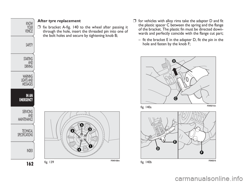
F0V0158mfig. 139
After tyre replacement
❒fix bracket A-fig. 140 to the wheel after passing it
through the hole, insert the threaded pin into one of
the bolt holes and secure by tightening knob B;
D
C
F0V0214mfig. 140a
F0V0215fig. 140b
❒for vehicles with alloy rims take the adapter D and fit
the plastic spacer C between the spring and the flange
of the bracket. The plastic fin must be directed down-
wards and perfectly coincide with the flange cut part;
– fit the bracket E in the adapter D, fit the pin in the
hole and fasten by the knob F;
155-190 DOBLO LUM EN 2e 7.0 21-05-2010 11:34 Pagina 162
Page 179 of 274
178
KNOW
YOUR
VEHICLE
SAFETY
STARTING
AND
DRIVING
WARNING
LIGHTS AND
MESSAGES
IN AN
EMERGENCY
SERVICING
AND
MAINTENANCE
TECHNICAL
SPECIFICATIONS
INDEX
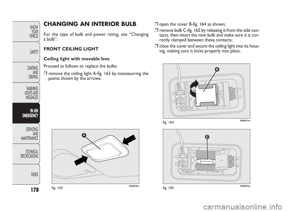
❒open the cover B-fig. 164 as shown;
❒remove bulb C-fig. 165 by releasing it from the side con-
tacts, then insert the new bulb and make sure it is cor-
rectly clamped between these contacts;
❒ close the cover and secure the ceiling light into its hous-
ing, making sure it locks properly into place.CHANGING AN INTERIOR BULB
For the type of bulb and power rating, see “Changing
a bulb”.
FRONT CEILING LIGHT
Ceiling light with movable lens
Proceed as follows to replace the bulbs:
❒remove the ceiling light A-fig. 163 by manoeuvring the
points shown by the arrows;
F0V0070mfig. 163F0V0072mfig. 165
F0V0071mfig. 164
155-190 DOBLO LUM EN 2e 7.0 21-05-2010 11:34 Pagina 178
Page 180 of 274
179
KNOW
YOUR
VEHICLE
SAFETY
STARTING
AND
DRIVING
WARNING
LIGHTS AND
MESSAGES
IN AN
EMERGENCY
SERVICING
AND
MAINTENANCE
TECHNICAL
SPECIFICATIONS
INDEX
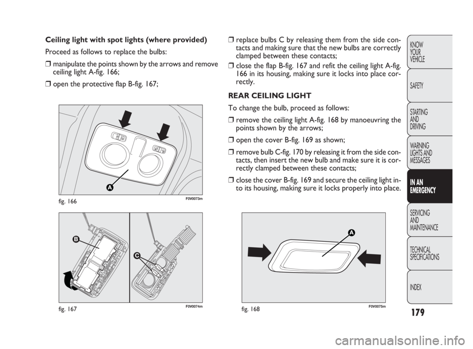
❒replace bulbs C by releasing them from the side con-
tacts and making sure that the new bulbs are correctly
clamped between these contacts;
❒ close the flap B-fig. 167 and refit the ceiling light A-fig.
166 in its housing, making sure it locks into place cor-
rectly.
REAR CEILING LIGHT
To change the bulb, proceed as follows:
❒remove the ceiling light A-fig. 168 by manoeuvring the
points shown by the arrows;
❒open the cover B-fig. 169 as shown;
❒remove bulb C-fig. 170 by releasing it from the side con-
tacts, then insert the new bulb and make sure it is cor-
rectly clamped between these contacts;
❒close the cover B-fig. 169 and secure the ceiling light in-
to its housing, making sure it locks properly into place. Ceiling light with spot lights (where provided)
Proceed as follows to replace the bulbs:
❒manipulate the points shown by the arrows and remove
ceiling light A-fig. 166;
❒open the protective flap B-fig. 167;
F0V0074mfig. 167
F0V0073mfig. 166
F0V0075mfig. 168
155-190 DOBLO LUM EN 2e 7.0 21-05-2010 11:34 Pagina 179
Page 185 of 274
184
KNOW
YOUR
VEHICLE
SAFETY
STARTING
AND
DRIVING
WARNING
LIGHTS AND
MESSAGES
IN AN
EMERGENCY
SERVICING
AND
MAINTENANCE
TECHNICAL
SPECIFICATIONS
INDEX
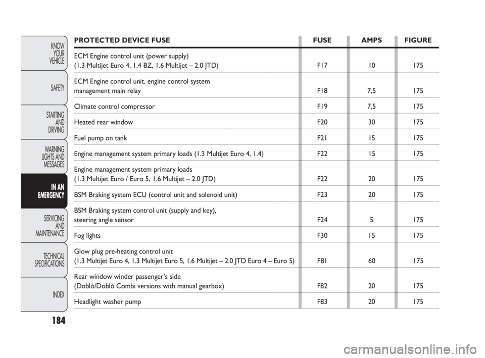
PROTECTED DEVICE FUSE FUSE AMPS FIGURE
ECM Engine control unit (power supply)
(1.3 Multijet Euro 4, 1.4 BZ, 1.6 Multijet – 2.0 JTD) F17 10 175
ECM Engine control unit, engine control system
management main relay F18 7,5 175
Climate control compressor F19 7,5 175
Heated rear window F20 30 175
Fuel pump on tank F21 15 175
Engine management system primary loads (1.3 Multijet Euro 4, 1.4) F22 15 175
Engine management system primary loads
(1.3 Multijet Euro / Euro 5, 1.6 Multijet – 2.0 JTD) F22 20 175
BSM Braking system ECU (control unit and solenoid unit) F23 20 175
BSM Braking system control unit (supply and key),
steering angle sensor F24 5 175
Fog lights F30 15 175
Glow plug pre-heating control unit
(1.3 Multijet Euro 4, 1.3 Multijet Euro 5, 1.6 Multijet – 2.0 JTD Euro 4 – Euro 5) F81 60 175
Rear window winder passenger’s side
(Doblò/Doblò Combi versions with manual gearbox) F82 20 175
Headlight washer pump F83 20 175
155-190 DOBLO LUM EN 2e 7.0 21-05-2010 11:34 Pagina 184