wheel FIAT DOBLO COMBI 2010 Owner handbook (in English)
[x] Cancel search | Manufacturer: FIAT, Model Year: 2010, Model line: DOBLO COMBI, Model: FIAT DOBLO COMBI 2010Pages: 274, PDF Size: 6.16 MB
Page 147 of 274
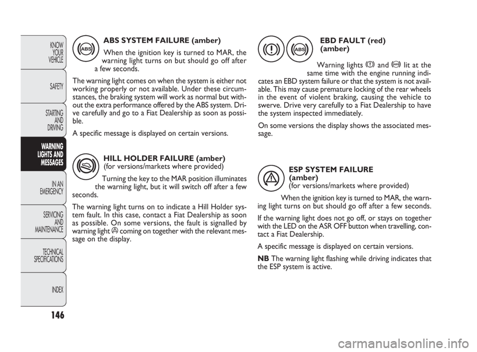
HILL HOLDER FAILURE (amber)
(for versions/markets where provided)
Turning the key to the MAR position illuminates
the warning light, but it will switch off after a few
seconds.
The warning light turns on to indicate a Hill Holder sys-
tem fault. In this case, contact a Fiat Dealership as soon
as possible. On some versions, the fault is signalled by
warning light ácoming on together with the relevant mes-
sage on the display.
*
ABS SYSTEM FAILURE (amber)
When the ignition key is turned to MAR, the
warning light turns on but should go off after
a few seconds.
The warning light comes on when the system is either not
working properly or not available. Under these circum-
stances, the braking system will work as normal but with-
out the extra performance offered by the ABS system. Dri-
ve carefully and go to a Fiat Dealership as soon as possi-
ble.
A specific message is displayed on certain versions.
146
KNOW
YOUR
VEHICLE
SAFETY
STARTING
AND
DRIVING
WARNING
LIGHTS AND
MESSAGES
IN AN
EMERGENCY
SERVICING
AND
MAINTENANCE
TECHNICAL
SPECIFICATIONS
INDEX
>
EBD FAULT (red)
(amber)
Warning lights
xand >lit at the
same time with the engine running indi-
cates an EBD system failure or that the system is not avail-
able. This may cause premature locking of the rear wheels
in the event of violent braking, causing the vehicle to
swerve. Drive very carefully to a Fiat Dealership to have
the system inspected immediately.
On some versions the display shows the associated mes-
sage.
> x
ESP SYSTEM FAILURE
(amber)
(for versions/markets where provided)
When the ignition key is turned to MAR, the warn-
ing light turns on but should go off after a few seconds.
If the warning light does not go off, or stays on together
with the LED on the ASR OFF button when travelling, con-
tact a Fiat Dealership.
A specific message is displayed on certain versions.
NBThe warning light flashing while driving indicates that
the ESP system is active.
á
143-154 DOBLO LUM EN 2e 7.0 21-05-2010 11:18 Pagina 146
Page 157 of 274
156
KNOW
YOUR
VEHICLE
SAFETY
STARTING
AND
DRIVING
WARNING
LIGHTS AND
MESSAGES
IN AN
EMERGENCY
SERVICING
AND
MAINTENANCE
TECHNICAL
SPECIFICATIONS
INDEX
Strictly avoid using a rapid battery charg-
er for jump starting: this could damage the
system electronics and the ignition and en-
gine supply control units.
This procedure must be performed by ex-
perts because incorrect actions may cause
considerable electrical discharge. Furthermore,
battery fluid is poisonous and corrosive: avoid con-
tact with skin and eyes. Keep naked flames and
lit cigarettes away from the battery. Do not cre-
ate sparks.
WARNING
BUMP STARTING
Never bump start the engine by pushing, towing or driving
downhill. This could cause fuel to flow into the catalytic
converter and damage it beyond repair.
IMPORTANT Remember that the brake booster and the
power steering system are not active until the engine is
started, so you will need to apply much more force to
the brake pedal or steering wheel.
CHANGING A TYRE
The vehicle is originally equipped with the Fix&Go auto-
matic quick tyre repair kit (see instructions in the next sec-
tion). As an alternative, the vehicle may have a normal-
sized spare wheel.
Wheel changing and correct use of the jack and spare
wheel call for some precautions, as listed below.
155-190 DOBLO LUM EN 2e 7.0 21-05-2010 11:34 Pagina 156
Page 158 of 274
157
KNOW
YOUR
VEHICLE
SAFETY
STARTING
AND
DRIVING
WARNING
LIGHTS AND
MESSAGES
IN AN
EMERGENCY
SERVICING
AND
MAINTENANCE
TECHNICAL
SPECIFICATIONS
INDEX
The spare wheel (where provided) is
specifically for your vehicle. Therefore, it
must not be used on other models. Do not use
spare wheels of other models on your vehicle. The
spare wheel should be used only in an emergency.
Use it as little as possible.
WARNING
Use your hazard lights, warning triangle,
etc to show that your car is stationary.
Passengers should get out of the car, particularly
if it is heavily loaded, and wait for the wheel to be
changed away from the traffic. If you are on a
steep slope or uneven surface, place wedges or
other suitable objects under the wheels to secure
the vehicle. Repair and refit the standard wheel
as soon as possible. Do not grease the bolt threads
before you fit them, because they could sudden-
ly come loose.
WARNING
Use the jack only to replace wheels on the
vehicle with which it is supplied or on oth-
er vehicles of the same model. Never use the jack
for other purposes, such as lifting other models.
Never use the jack to carry out repairs under the
vehicle. Incorrect positioning of the jack may
cause the lifted vehicle to fall. Do not use the jack
for loads higher than the one shown on its label.
WARNING
Incorrect hub cap assembly may cause it
to come off when the car is moving. Nev-
er tamper with the inflation valve. Never intro-
duce tools of any kind between the rim and the
tyre. Check tyre and spare wheel pressures regu-
larly, referring to the values shown in the “Tech-
nical specifications” section.
WARNING
155-190 DOBLO LUM EN 2e 7.0 21-05-2010 11:34 Pagina 157
Page 159 of 274
F0V0148mfig. 130
F0V0149mfig. 129
158
KNOW
YOUR
VEHICLE
SAFETY
STARTING
AND
DRIVING
WARNING
LIGHTS AND
MESSAGES
IN AN
EMERGENCY
SERVICING
AND
MAINTENANCE
TECHNICAL
SPECIFICATIONS
INDEX
Important notes:
❒ the jack weighs 4 kg;
❒the jack requires no adjustment;
❒the jack cannot be repaired; if it breaks, it must be re-
placed with a new one of the same type;
❒no tool other than the cranking handle may be fitted on
the jack.
To change a tyre, proceed as follows:
❒stop the vehicle in a position where it is not a danger
for other traffic and where you can replace the wheel
safely. The ground should be flat and solid;
❒turn the engine off and engage the handbrake;
❒engage first gear or reverse;
❒wear the reflective safety jacket (compulsory by law)
before getting out of the vehicle;
❒ indicate that the vehicle is parked up by using the de-
vices required by law in the country in which you are
travelling (e.g. warning triangle, hazard lights etc.);
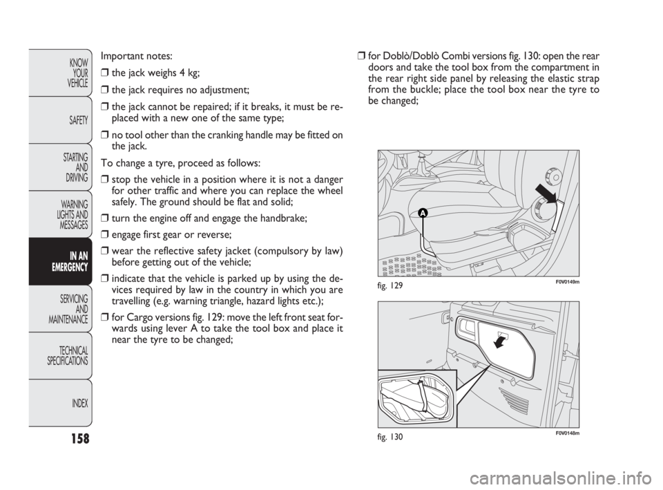
❒for Cargo versions fig. 129: move the left front seat for-
wards using lever A to take the tool box and place it
near the tyre to be changed;❒for Doblò/Doblò Combi versions fig. 130: open the rear
doors and take the tool box from the compartment in
the rear right side panel by releasing the elastic strap
from the buckle; place the tool box near the tyre to
be changed;
155-190 DOBLO LUM EN 2e 7.0 21-05-2010 11:34 Pagina 158
Page 160 of 274
159
KNOW
YOUR
VEHICLE
SAFETY
STARTING
AND
DRIVING
WARNING
LIGHTS AND
MESSAGES
IN AN
EMERGENCY
SERVICING
AND
MAINTENANCE
TECHNICAL
SPECIFICATIONS
INDEX
F0V0193mfig. 133
F0V0151mfig. 132
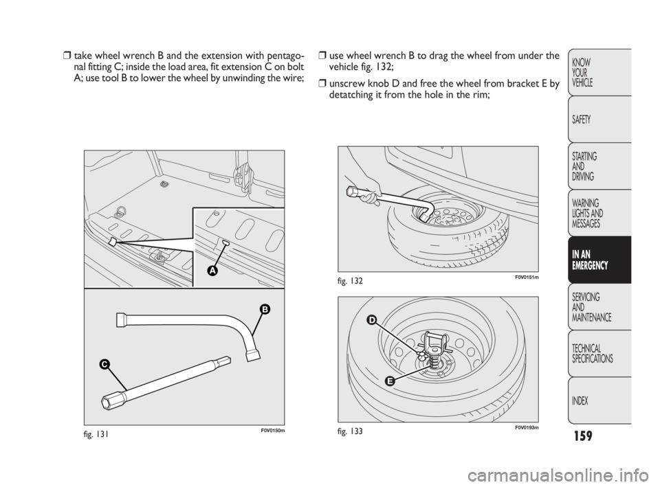
❒use wheel wrench B to drag the wheel from under the
vehicle fig. 132;
❒unscrew knob D and free the wheel from bracket E by
detatching it from the hole in the rim; ❒take wheel wrench B and the extension with pentago-
nal fitting C; inside the load area, fit extension C on bolt
A; use tool B to lower the wheel by unwinding the wire;
B B
C
C
F0V0150mfig. 131
155-190 DOBLO LUM EN 2e 7.0 21-05-2010 11:34 Pagina 159
Page 161 of 274
160
KNOW
YOUR
VEHICLE
SAFETY
STARTING
AND
DRIVING
WARNING
LIGHTS AND
MESSAGES
IN AN
EMERGENCY
SERVICING
AND
MAINTENANCE
TECHNICAL
SPECIFICATIONS
INDEX
F0V0153mfig. 134bF0V0155mfig. 136
F0V0154mfig. 135
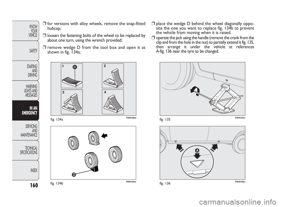
❒place the wedge D behind the wheel diagonally oppo-
site the one you want to replace fig. 134b to prevent
the vehicle from moving when it is raised.
❒
operate the jack using the handle (remove the crank from the
clip and from the hole in the nut) to partially extend it fig. 135,
then arrange it under the vehicle at references
A-fig. 136 near the tyre to be changed.
❒for versions with alloy wheels, remove the snap-fitted
hubcap;
❒loosen the fastening bolts of the wheel to be replaced by
about one turn, using the wrench provided;
❒remove wedge D from the tool box and open it as
shown in fig. 134a;
D
F0V0192mfig. 134a
155-190 DOBLO LUM EN 2e 7.0 21-05-2010 11:34 Pagina 160
Page 162 of 274
161
KNOW
YOUR
VEHICLE
SAFETY
STARTING
AND
DRIVING
WARNING
LIGHTS AND
MESSAGES
IN AN
EMERGENCY
SERVICING
AND
MAINTENANCE
TECHNICAL
SPECIFICATIONS
INDEX
F0V0156mfig. 137F0V0157mfig. 138
❒loosen the fastening bolts completely and then remove
the wheel;
❒make sure the contact surfaces between spare wheel
and hub are clean so that the fastening bolts will not
come loose;
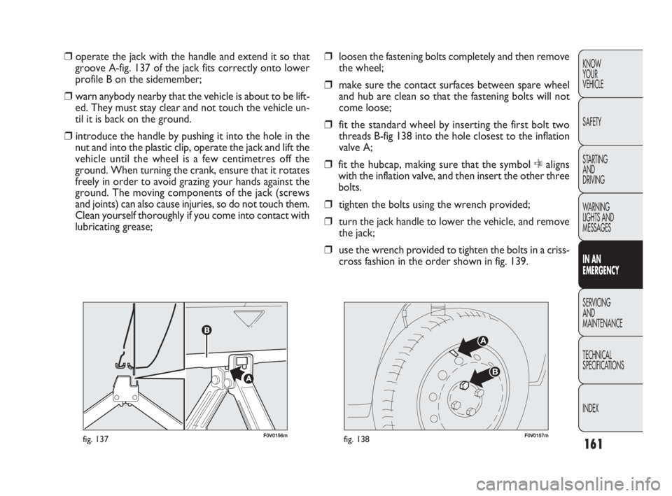
❒fit the standard wheel by inserting the first bolt two
threads B-fig 138 into the hole closest to the inflation
valve A;
❒fit the hubcap, making sure that the symbol Caligns
with the inflation valve, and then insert the other three
bolts.
❒tighten the bolts using the wrench provided;
❒turn the jack handle to lower the vehicle, and remove
the jack;
❒use the wrench provided to tighten the bolts in a criss-
cross fashion in the order shown in fig. 139. ❒operate the jack with the handle and extend it so that
groove A-fig. 137 of the jack fits correctly onto lower
profile B on the sidemember;
❒warn anybody nearby that the vehicle is about to be lift-
ed. They must stay clear and not touch the vehicle un-
til it is back on the ground.
❒introduce the handle by pushing it into the hole in the
nut and into the plastic clip, operate the jack and lift the
vehicle until the wheel is a few centimetres off the
ground. When turning the crank, ensure that it rotates
freely in order to avoid grazing your hands against the
ground. The moving components of the jack (screws
and joints) can also cause injuries, so do not touch them.
Clean yourself thoroughly if you come into contact with
lubricating grease;
155-190 DOBLO LUM EN 2e 7.0 21-05-2010 11:34 Pagina 161
Page 163 of 274
162
KNOW
YOUR
VEHICLE
SAFETY
STARTING
AND
DRIVING
WARNING
LIGHTS AND
MESSAGES
IN AN
EMERGENCY
SERVICING
AND
MAINTENANCE
TECHNICAL
SPECIFICATIONS
INDEX
F0V0158mfig. 139
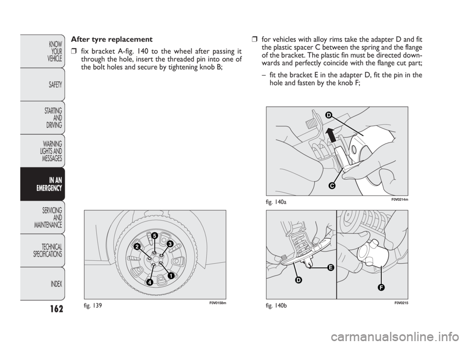
After tyre replacement
❒fix bracket A-fig. 140 to the wheel after passing it
through the hole, insert the threaded pin into one of
the bolt holes and secure by tightening knob B;
D
C
F0V0214mfig. 140a
F0V0215fig. 140b
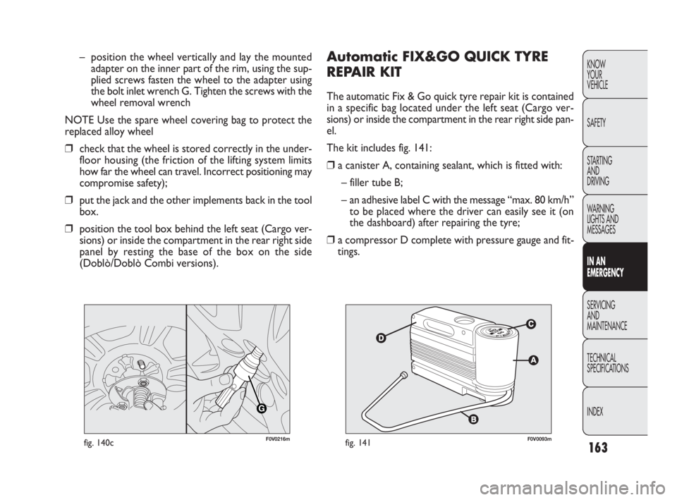
❒for vehicles with alloy rims take the adapter D and fit
the plastic spacer C between the spring and the flange
of the bracket. The plastic fin must be directed down-
wards and perfectly coincide with the flange cut part;
– fit the bracket E in the adapter D, fit the pin in the
hole and fasten by the knob F;
155-190 DOBLO LUM EN 2e 7.0 21-05-2010 11:34 Pagina 162
Page 164 of 274
163
KNOW
YOUR
VEHICLE
SAFETY
STARTING
AND
DRIVING
WARNING
LIGHTS AND
MESSAGES
IN AN
EMERGENCY
SERVICING
AND
MAINTENANCE
TECHNICAL
SPECIFICATIONS
INDEX
Automatic FIX&GO QUICK TYRE
REPAIR KIT
The automatic Fix & Go quick tyre repair kit is contained
in a specific bag located under the left seat (Cargo ver-
sions) or inside the compartment in the rear right side pan-
el.
The kit includes fig. 141:
❒a canister A, containing sealant, which is fitted with:
– filler tube B;
– an adhesive label C with the message “max. 80 km/h”
to be placed where the driver can easily see it (on
the dashboard) after repairing the tyre;
❒a compressor D complete with pressure gauge and fit-
tings. – position the wheel vertically and lay the mounted
adapter on the inner part of the rim, using the sup-
plied screws fasten the wheel to the adapter using
the bolt inlet wrench G. Tighten the screws with the
wheel removal wrench
NOTE Use the spare wheel covering bag to protect the
replaced alloy wheel
❒check that the wheel is stored correctly in the under-
floor housing (the friction of the lifting system limits
how far the wheel can travel. Incorrect positioning may
compromise safety);
❒put the jack and the other implements back in the tool
box.
❒position the tool box behind the left seat (Cargo ver-
sions) or inside the compartment in the rear right side
panel by resting the base of the box on the side
(Doblò/Doblò Combi versions).
G
F0V0216mfig. 140cF0V0093mfig. 141
155-190 DOBLO LUM EN 2e 7.0 21-05-2010 11:34 Pagina 163
Page 166 of 274
165
KNOW
YOUR
VEHICLE
SAFETY
STARTING
AND
DRIVING
WARNING
LIGHTS AND
MESSAGES
IN AN
EMERGENCY
SERVICING
AND
MAINTENANCE
TECHNICAL
SPECIFICATIONS
INDEX
F0V0095mfig. 143
INFLATION PROCEDURE
If the wheel rim is damaged (the channel
is so deformed as to cause an air leakage)
it cannot be repaired. Do not remove foreign bod-
ies (screws or nails) from the tyre.
WARNING
The cylinder contains ethylene glycol. It
contains latex, which may cause an aller-
gic reaction. Harmful if swallowed. Irritates the
eyes. There could be a reaction in case of inhala-
tion or contact. Avoid contact with your eyes, skin
and clothes. In the event of contact, wash imme-
diately with plenty of water. Do not induce vom-
iting if swallowed. Rinse your mouth out and drink
plenty of water. Call a doctor immediately. Keep
out of the reach of children. The product must not
be used by asthmatics. Do not breathe in the
vapours during insertion and suction. Call a doc-
tor immediately if allergic reactions are noted.
Store the canister in its proper compartment,
away from sources of heat. The sealant has an ex-
piry date. Replace the cylinder if its sealant is out
of date.
WARNING
Put on the protective gloves provided with
the quick tyre repair kit.
WARNING
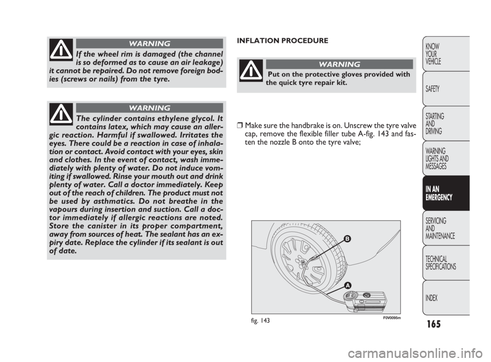
❒Make sure the handbrake is on. Unscrew the tyre valve
cap, remove the flexible filler tube A-fig. 143 and fas-
ten the nozzle B onto the tyre valve;
155-190 DOBLO LUM EN 2e 7.0 21-05-2010 11:34 Pagina 165