sensor FIAT DOBLO COMBI 2010 Owner handbook (in English)
[x] Cancel search | Manufacturer: FIAT, Model Year: 2010, Model line: DOBLO COMBI, Model: FIAT DOBLO COMBI 2010Pages: 274, PDF Size: 6.16 MB
Page 52 of 274
51
KNOW
YOUR
VEHICLE
SAFETY
STARTING
AND
DRIVING
WARNING
LIGHTS AND
MESSAGES
IN AN
EMERGENCY
SERVICING
AND
MAINTENANCE
TECHNICAL
SPECIFICATIONS
INDEX
Manual selections will always take priority over automat-
ic settings and will be stored until the user switches the
system back to automatic operation by pressing the
AUTO button again, except for when the system inter-
venes for particular safety-related reasons. You can adjust
one function manually without affecting the automatic con-
trol of the others.
The temperature of the air introduced is always controlled
automatically, depending on the temperature set in the dis-
play (except when the system is off or in certain condi-
tions when the compressor is switched off).
The system allows the following parameters and functions
to be set or altered manually: air temperature, fan speed
(continuous variation); air distribution in seven positions;
compressor enablement; fast defrosting/demisting func-
tion; air recirculation; switching off the system.AUTOMATIC CLIMATE CONTROL
(for versions/markets, where provided)
GENERAL INFORMATION
The automatic climate control system adjusts the tem-
perature, the quantity and the distribution of the air in the
passenger compartment. The temperature control is based
on the “equivalent temperature”: in other words, the sys-
tem continuously works to keep the comfort level inside
the vehicle constant and to compensate for possible vari-
ations in outside conditions, including the solar radiation
detected by a dedicated sensor. The automatically con-
trolled parameters and functions are:
❒air temperature at the vents;
❒air distribution at the vents;
❒fan speed
(continuous air flow variation);
❒compressor activation
(to cool/dehumidify the air);
❒air recirculation.
All functions may be changed manually. In other words,
you may select one or more functions and change the pa-
rameters as required. Automatic control of the manually
changed functions will be deactivated: the system will on-
ly override your settings for safety related reasons (e.g.
risk of misting up).
035-114 DOBLO LUM EN 2e 7.0 21-05-2010 9:54 Pagina 51
Page 104 of 274
103
KNOW
YOUR
VEHICLE
SAFETY
STARTING
AND
DRIVING
WARNING
LIGHTS AND
MESSAGES
IN AN
EMERGENCY
SERVICING
AND
MAINTENANCE
TECHNICAL
SPECIFICATIONS
INDEX
F0V0077mfig. 102
❒becomes continuous when the distance between the
vehicle and the obstacle is less than about 30 cm, and
stops immediately if the distance increases;
❒remains constant if the distance between the vehicle
and the obstacle remains unchanged.
FAILURE INDICATIONS
Parking sensor failures are indicated, when engaging re-
verse gear, by a three second beep.
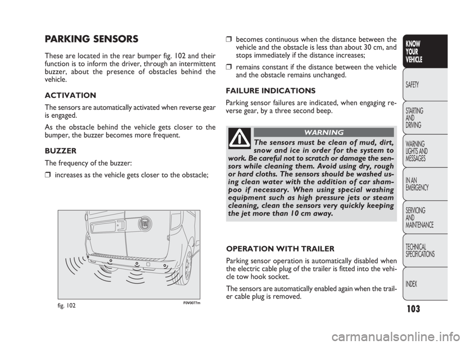
PARKING SENSORS
These are located in the rear bumper fig. 102 and their
function is to inform the driver, through an intermittent
buzzer, about the presence of obstacles behind the
vehicle.
ACTIVATION
The sensors are automatically activated when reverse gear
is engaged.
As the obstacle behind the vehicle gets closer to the
bumper, the buzzer becomes more frequent.
BUZZER
The frequency of the buzzer:
❒increases as the vehicle gets closer to the obstacle;
OPERATION WITH TRAILER
Parking sensor operation is automatically disabled when
the electric cable plug of the trailer is fitted into the vehi-
cle tow hook socket.
The sensors are automatically enabled again when the trail-
er cable plug is removed.
The sensors must be clean of mud, dirt,
snow and ice in order for the system to
work. Be careful not to scratch or damage the sen-
sors while cleaning them. Avoid using dry, rough
or hard cloths. The sensors should be washed us-
ing clean water with the addition of car sham-
poo if necessary. When using special washing
equipment such as high pressure jets or steam
cleaning, clean the sensors very quickly keeping
the jet more than 10 cm away.
WARNING
035-114 DOBLO LUM EN 2e 7.0 21-05-2010 9:54 Pagina 103
Page 105 of 274
F0V0040mfig. 103
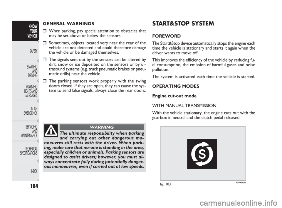
START&STOP SYSTEM
FOREWORD
The Start&Stop device automatically stops the engine each
time the vehicle is stationary and starts it again when the
driver wants to move off.
This improves the efficiency of the vehicle by reducing fu-
el consumption, the emission of harmful gases and noise
pollution.
The system is activated each time the vehicle is started.
OPERATING MODES
Engine cut-out mode
WITH MANUAL TRANSMISSION
With the vehicle stationary, the engine cuts out with the
gearbox in neutral and the clutch pedal released.
104
KNOW
YOUR
VEHICLE
SAFETY
STARTING
AND
DRIVING
WARNING
LIGHTS AND
MESSAGES
IN AN
EMERGENCY
SERVICING
AND
MAINTENANCE
TECHNICAL
SPECIFICATIONS
INDEX
GENERAL WARNINGS
❒When parking, pay special attention to obstacles that
may be set above or below the sensors.
❒Sometimes, objects located very near the rear of the
vehicle are not detected and could therefore damage
the vehicle or be damaged themselves.
❒The signals sent out by the sensors can be altered by
dirt, snow or ice deposited on the sensors or by ul-
trasound systems (e.g. truck pneumatic brakes or pneu-
matic drills) near the vehicle.
❒The parking sensors work properly with the swing
doors closed. If they are open, they can cause the sys-
tem to send false signals: always close the rear doors.
The ultimate responsibility when parking
and carrying out other dangerous ma-
noeuvres still rests with the driver. When park-
ing, make sure that no-one is standing in the area,
especially children or animals. Parking sensors are
designed to assist drivers; however, you must al-
ways concentrate fully during potentially danger-
ous manoeuvres, even if carried out at low speeds.
WARNING
035-114 DOBLO LUM EN 2e 7.0 21-05-2010 9:54 Pagina 104
Page 108 of 274
107
KNOW
YOUR
VEHICLE
SAFETY
STARTING
AND
DRIVING
WARNING
LIGHTS AND
MESSAGES
IN AN
EMERGENCY
SERVICING
AND
MAINTENANCE
TECHNICAL
SPECIFICATIONS
INDEX
F0V0041mfig. 105
ENERGY SAVING FUNCTION
(for versions/markets where provided)
If, after the engine has been automatically restarted, the
driver does not take any action for a period of about 3 min-
utes, the Start&Stop system will definitively stop the en-
gine to avoid fuel consumption. The engine can only be
started using the key in such cases.
N.B.: In any case, it is possible to keep the engine running
by deactivating the Start&Stop system.
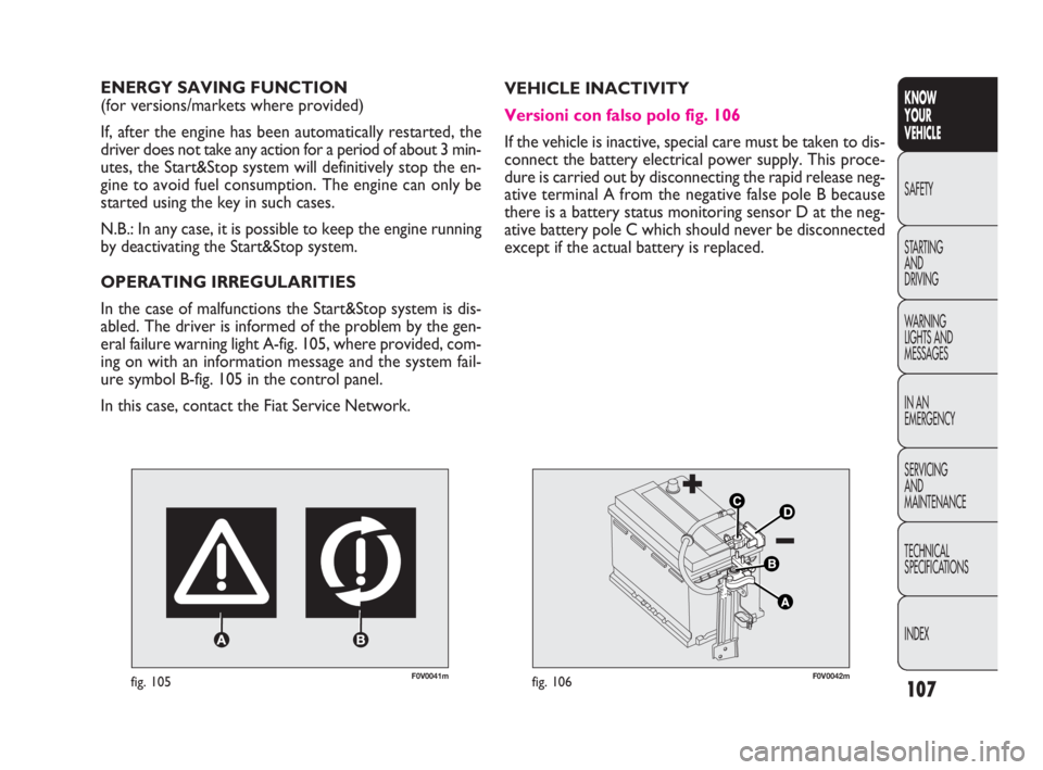
OPERATING IRREGULARITIES
In the case of malfunctions the Start&Stop system is dis-
abled. The driver is informed of the problem by the gen-
eral failure warning light A-fig. 105, where provided, com-
ing on with an information message and the system fail-
ure symbol B-fig. 105 in the control panel.
In this case, contact the Fiat Service Network.VEHICLE INACTIVITY
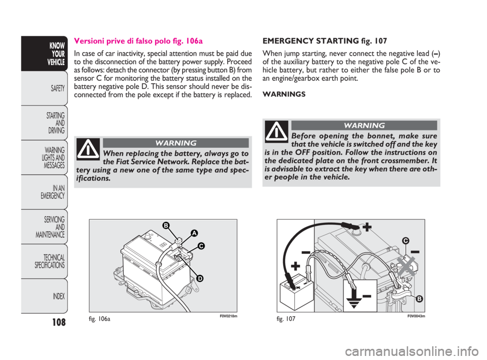
Versioni con falso polo fig. 106
If the vehicle is inactive, special care must be taken to dis-
connect the battery electrical power supply. This proce-
dure is carried out by disconnecting the rapid release neg-
ative terminal A from the negative false pole B because
there is a battery status monitoring sensor D at the neg-
ative battery pole C which should never be disconnected
except if the actual battery is replaced.
F0V0042mfig. 106
035-114 DOBLO LUM EN 2e 7.0 21-05-2010 9:54 Pagina 107
Page 109 of 274
108
KNOW
YOUR
VEHICLE
SAFETY
STARTING
AND
DRIVING
WARNING
LIGHTS AND
MESSAGES
IN AN
EMERGENCY
SERVICING
AND
MAINTENANCE
TECHNICAL
SPECIFICATIONS
INDEX
F0V0043mfig. 107
EMERGENCY STARTING fig. 107
When jump starting, never connect the negative lead (–)
of the auxiliary battery to the negative pole C of the ve-
hicle battery, but rather to either the false pole B or to
an engine/gearbox earth point.
WARNINGS
When replacing the battery, always go to
the Fiat Service Network. Replace the bat-
tery using a new one of the same type and spec-
ifications.
WARNINGBefore opening the bonnet, make sure
that the vehicle is switched off and the key
is in the OFF position. Follow the instructions on
the dedicated plate on the front crossmember. It
is advisable to extract the key when there are oth-
er people in the vehicle.
WARNING
F0V0218mfig. 106a
Versioni prive di falso polo fig. 106a
In case of car inactivity, special attention must be paid due
to the disconnection of the battery power supply. Proceed
as follows: detach the connector (by pressing button B) from
sensor C for monitoring the battery status installed on the
battery negative pole D. This sensor should never be dis-
connected from the pole except if the battery is replaced.
035-114 DOBLO LUM EN 2e 7.0 21-05-2010 9:54 Pagina 108
Page 114 of 274
113
KNOW
YOUR
VEHICLE
SAFETY
STARTING
AND
DRIVING
WARNING
LIGHTS AND
MESSAGES
IN AN
EMERGENCY
SERVICING
AND
MAINTENANCE
TECHNICAL
SPECIFICATIONS
INDEX
PROTECTING THE ENVIRONMENT
The devices for reducing petrol engine emissions are the
following:
❒three-way catalytic converter;
❒Lambda sensors;
❒evaporation prevention system.
In addition, do not let the engine run, even for a test, with
one or more spark plugs disconnected.
The following devices are used for reducing diesel fuel en-
gine emissions:
❒oxidising catalytic converter;
❒exhaust gas recirculation system (EGR);
❒diesel particulate filter (DPF) (for versions/markets
where provided). To close
1) Fit the cap (complete with key) and turn it clockwise
until it clicks once or more.
2) Turn the key clockwise and extract it, then close the
flap.
The hermetic seal may cause a slight increase in pressure
in the tank. A suction noise when you release the cap is
therefore entirely normal.
Do not place naked flames or lit cigarettes
near to the fuel tank opening: fire risk. Keep
your face away from the fuel tank open-
ing to avoid breathing in harmful vapours.
035-114 DOBLO LUM EN 2e 7.0 21-05-2010 9:55 Pagina 113
Page 153 of 274
152
KNOW
YOUR
VEHICLE
SAFETY
STARTING
AND
DRIVING
WARNING
LIGHTS AND
MESSAGES
IN AN
EMERGENCY
SERVICING
AND
MAINTENANCE
TECHNICAL
SPECIFICATIONS
INDEX
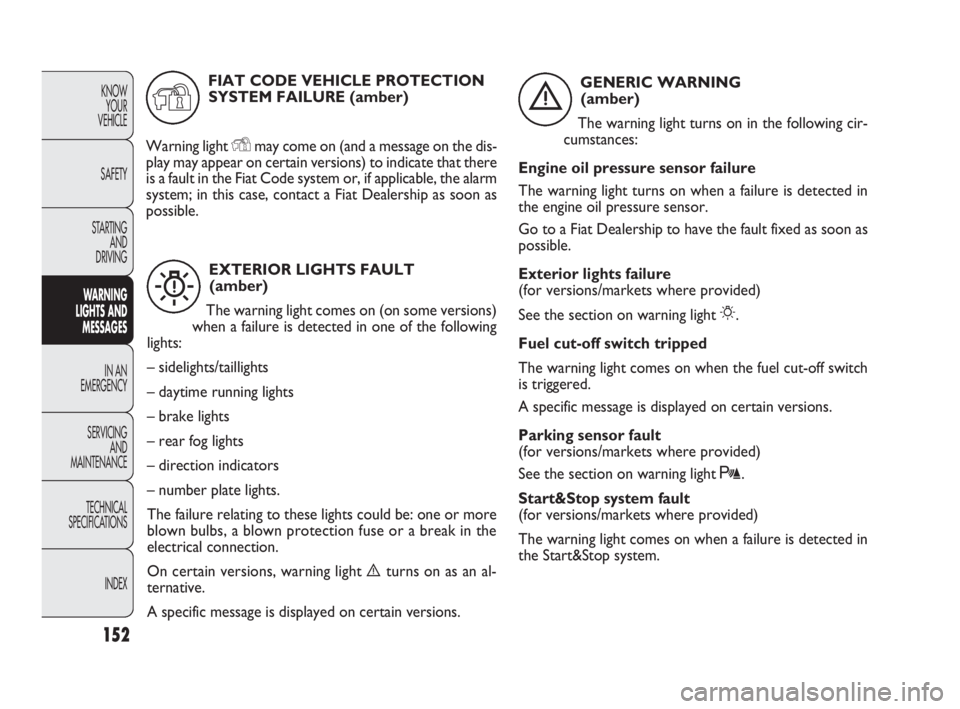
EXTERIOR LIGHTS FAULT
(amber)
The warning light comes on (on some versions)
when a failure is detected in one of the following
lights:
– sidelights/taillights
– daytime running lights
– brake lights
– rear fog lights
– direction indicators
– number plate lights.
The failure relating to these lights could be: one or more
blown bulbs, a blown protection fuse or a break in the
electrical connection.
On certain versions, warning light èturns on as an al-
ternative.
A specific message is displayed on certain versions.
W
GENERIC WARNING
(amber)
The warning light turns on in the following cir-
cumstances:
Engine oil pressure sensor failure
The warning light turns on when a failure is detected in
the engine oil pressure sensor.
Go to a Fiat Dealership to have the fault fixed as soon as
possible.
Exterior lights failure
(for versions/markets where provided)
See the section on warning light
6.
Fuel cut-off switch tripped
The warning light comes on when the fuel cut-off switch
is triggered.
A specific message is displayed on certain versions.
Parking sensor fault
(for versions/markets where provided)
See the section on warning light t.
Start&Stop system fault
(for versions/markets where provided)
The warning light comes on when a failure is detected in
the Start&Stop system.
è
FIAT CODE VEHICLE PROTECTION
SYSTEM FAILURE (amber)
Warning light
Ymay come on (and a message on the dis-
play may appear on certain versions) to indicate that there
is a fault in the Fiat Code system or, if applicable, the alarm
system; in this case, contact a Fiat Dealership as soon as
possible.
Y
143-154 DOBLO LUM EN 2e 7.0 21-05-2010 11:18 Pagina 152
Page 154 of 274
153
KNOW
YOUR
VEHICLE
SAFETY
STARTING
AND
DRIVING
WARNING
LIGHTS AND
MESSAGES
IN AN
EMERGENCY
SERVICING
AND
MAINTENANCE
TECHNICAL
SPECIFICATIONS
INDEX
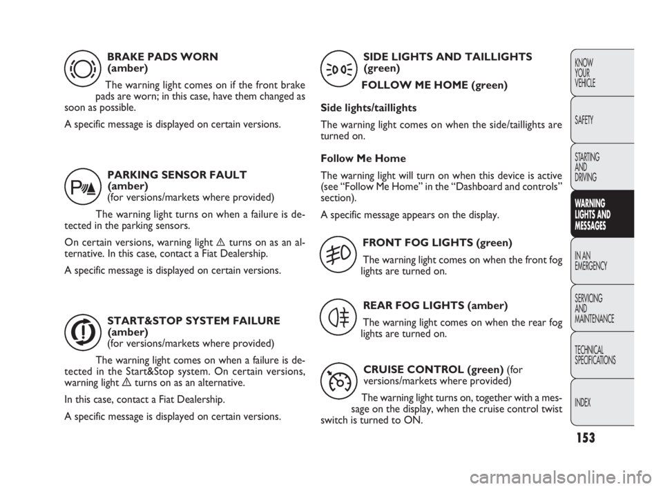
BRAKE PADS WORN
(amber)
The warning light comes on if the front brake
pads are worn; in this case, have them changed as
soon as possible.
A specific message is displayed on certain versions.
d
PARKING SENSOR FAULT
(amber)
(for versions/markets where provided)
The warning light turns on when a failure is de-
tected in the parking sensors.
On certain versions, warning light
èturns on as an al-
ternative. In this case, contact a Fiat Dealership.
A specific message is displayed on certain versions.
t
START&STOP SYSTEM FAILURE
(amber)
(for versions/markets where provided)
The warning light comes on when a failure is de-
tected in the Start&Stop system. On certain versions,
warning light èturns on as an alternative.
In this case, contact a Fiat Dealership.
A specific message is displayed on certain versions.
j
SIDE LIGHTS AND TAILLIGHTS
(green)
FOLLOW ME HOME (green)
Side lights/taillights
The warning light comes on when the side/taillights are
turned on.
Follow Me Home
The warning light will turn on when this device is active
(see “Follow Me Home” in the “Dashboard and controls”
section).
A specific message appears on the display.
3
FRONT FOG LIGHTS (green)
The warning light comes on when the front fog
lights are turned on.
5
REAR FOG LIGHTS (amber)
The warning light comes on when the rear fog
lights are turned on.
4
CRUISE CONTROL (green) (for
versions/markets where provided)
The warning light turns on, together with a mes-
sage on the display, when the cruise control twist
switch is turned to ON.
Ü
143-154 DOBLO LUM EN 2e 7.0 21-05-2010 11:18 Pagina 153
Page 185 of 274
184
KNOW
YOUR
VEHICLE
SAFETY
STARTING
AND
DRIVING
WARNING
LIGHTS AND
MESSAGES
IN AN
EMERGENCY
SERVICING
AND
MAINTENANCE
TECHNICAL
SPECIFICATIONS
INDEX
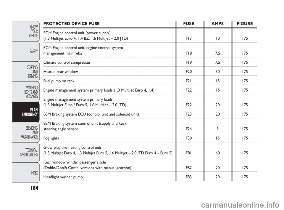
PROTECTED DEVICE FUSE FUSE AMPS FIGURE
ECM Engine control unit (power supply)
(1.3 Multijet Euro 4, 1.4 BZ, 1.6 Multijet – 2.0 JTD) F17 10 175
ECM Engine control unit, engine control system
management main relay F18 7,5 175
Climate control compressor F19 7,5 175
Heated rear window F20 30 175
Fuel pump on tank F21 15 175
Engine management system primary loads (1.3 Multijet Euro 4, 1.4) F22 15 175
Engine management system primary loads
(1.3 Multijet Euro / Euro 5, 1.6 Multijet – 2.0 JTD) F22 20 175
BSM Braking system ECU (control unit and solenoid unit) F23 20 175
BSM Braking system control unit (supply and key),
steering angle sensor F24 5 175
Fog lights F30 15 175
Glow plug pre-heating control unit
(1.3 Multijet Euro 4, 1.3 Multijet Euro 5, 1.6 Multijet – 2.0 JTD Euro 4 – Euro 5) F81 60 175
Rear window winder passenger’s side
(Doblò/Doblò Combi versions with manual gearbox) F82 20 175
Headlight washer pump F83 20 175
155-190 DOBLO LUM EN 2e 7.0 21-05-2010 11:34 Pagina 184
Page 186 of 274
185
KNOW
YOUR
VEHICLE
SAFETY
STARTING
AND
DRIVING
WARNING
LIGHTS AND
MESSAGES
IN AN
EMERGENCY
SERVICING
AND
MAINTENANCE
TECHNICAL
SPECIFICATIONS
INDEX
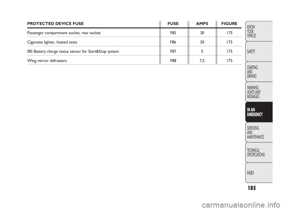
PROTECTED DEVICE FUSE FUSE AMPS FIGURE
Passenger compartment socket, rear socket F85 30 175
Cigarette lighter, heated seats F86 30 175
IBS Battery charge status sensor for Start&Stop system F87 5 175
Wing mirror defrosters F88 7,5 175
155-190 DOBLO LUM EN 2e 7.0 21-05-2010 11:34 Pagina 185