diagram FIAT DOBLO COMBI 2011 Owner handbook (in English)
[x] Cancel search | Manufacturer: FIAT, Model Year: 2011, Model line: DOBLO COMBI, Model: FIAT DOBLO COMBI 2011Pages: 274, PDF Size: 5.96 MB
Page 67 of 274
66
KNOW
YOUR
VEHICLE
SAFETY
STAR
TING
AND
DRIVING
WARNING
LIGHTS AND
MESSAGES
IN AN
EMERGENCY
SERVICING
AND
MAINTENANCE
TECHNICAL
SPECIFICATIONS
INDEX
F0V0056mfig. 50F0V0057mfig. 51
WARNING Before getting out of the vehicle, make sure
both switches are in the middle position; when the doors
are closed, the lights switch off to prevent the battery from
being run down. In any case, if the switch is left in the on
position, the courtesy light switches off automatically 15
minutes after the engine is switched off.
REAR COURTESY LIGHT WITH MOVABLE
LENS
(Doblò/Doblò Combi versions)
The light comes on automatically when a front door or
sliding side door is opened and goes out when it is closed.
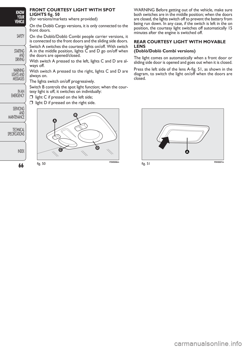
Press the left side of the lens A-fig. 51, as shown in the
diagram, to switch the light on/off when the doors are
closed. FRONT COURTESY LIGHT WITH SPOT
LIGHTS fig. 50
(for versions/markets where provided)
On the Doblò Cargo versions, it is only connected to the
front doors.
On the Doblò/Doblò Combi people carrier versions, it
is connected to the front doors and the sliding side doors.
Switch A switches the courtesy lights on/off. With switch
A in the middle position, lights C and D go on/off when
the doors are opened/closed.
With switch A pressed to the left, lights C and D are al-
ways off.
With switch A pressed to the right, lights C and D are
always on.
The lights switch on/off progressively.
Switch B controls the spot light function; when the cour-
tesy light is off, it switches on individually:
❒light C if pressed on the left side;
❒light D if pressed on the right side.
Page 68 of 274
67
KNOW
YOUR
VEHICLE
SAFETY
STAR
TING
AND
DRIVING
WARNING
LIGHTS AND
MESSAGES
IN AN
EMERGENCY
SERVICING
AND
MAINTENANCE
TECHNICAL
SPECIFICATIONS
INDEX
F0V0171mfig. 52
REAR COURTESY LIGHT WITH MOVABLE
LENS
(Cargo versions without fixed window)
This is located on the rear panel of the load compartment.
The light comes on automatically when you open the slid-
ing side doors (for versions/markets where provided) and
the rear swing doors/tailgate (for versions/markets where
provided), and goes out when you close them.
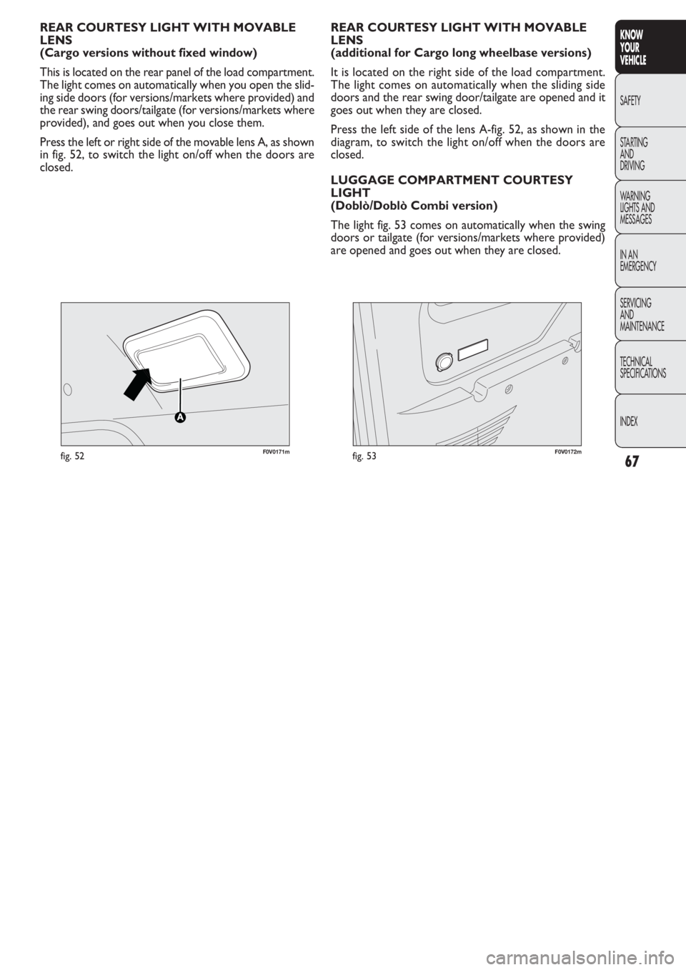
Press the left or right side of the movable lens A, as shown
in fig. 52, to switch the light on/off when the doors are
closed.REAR COURTESY LIGHT WITH MOVABLE
LENS
(additional for Cargo long wheelbase versions)
It is located on the right side of the load compartment.
The light comes on automatically when the sliding side
doors and the rear swing door/tailgate are opened and it
goes out when they are closed.
Press the left side of the lens A-fig. 52, as shown in the
diagram, to switch the light on/off when the doors are
closed.
LUGGAGE COMPARTMENT COURTESY
LIGHT
(Doblò/Doblò Combi version)
The light fig. 53 comes on automatically when the swing
doors or tailgate (for versions/markets where provided)
are opened and goes out when they are closed.
F0V0172mfig. 53
Page 81 of 274
80
KNOW
YOUR
VEHICLE
SAFETY
STAR
TING
AND
DRIVING
WARNING
LIGHTS AND
MESSAGES
IN AN
EMERGENCY
SERVICING
AND
MAINTENANCE
TECHNICAL
SPECIFICATIONS
INDEX
F0V0066mfig. 76F0V0186mfig. 77
The device remains engaged even if the doors are unlocked
remotely. Opening/closing from the inside
(Cargo versions, where provided)
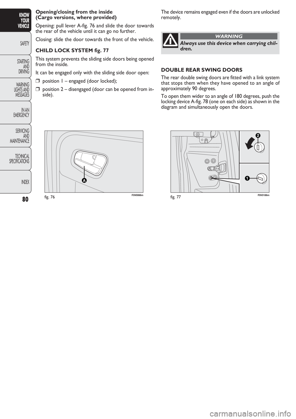
Opening: pull lever A-fig. 76 and slide the door towards
the rear of the vehicle until it can go no further.
Closing: slide the door towards the front of the vehicle.
CHILD LOCK SYSTEM fig. 77
This system prevents the sliding side doors being opened
from the inside.
It can be engaged only with the sliding side door open:
❒position 1 – engaged (door locked);
❒position 2 – disengaged (door can be opened from in-
side).
Always use this device when carrying chil-
dren.
WARNING
DOUBLE REAR SWING DOORS
The rear double swing doors are fitted with a link system
that stops them when they have opened to an angle of
approximately 90 degrees.
To open them wider to an angle of 180 degrees, push the
locking device A-fig. 78 (one on each side) as shown in the
diagram and simultaneously open the doors.
Page 83 of 274
82
KNOW
YOUR
VEHICLE
SAFETY
STAR
TING
AND
DRIVING
WARNING
LIGHTS AND
MESSAGES
IN AN
EMERGENCY
SERVICING
AND
MAINTENANCE
TECHNICAL
SPECIFICATIONS
INDEX
F0V0078mfig. 81
F0V0080mfig. 80
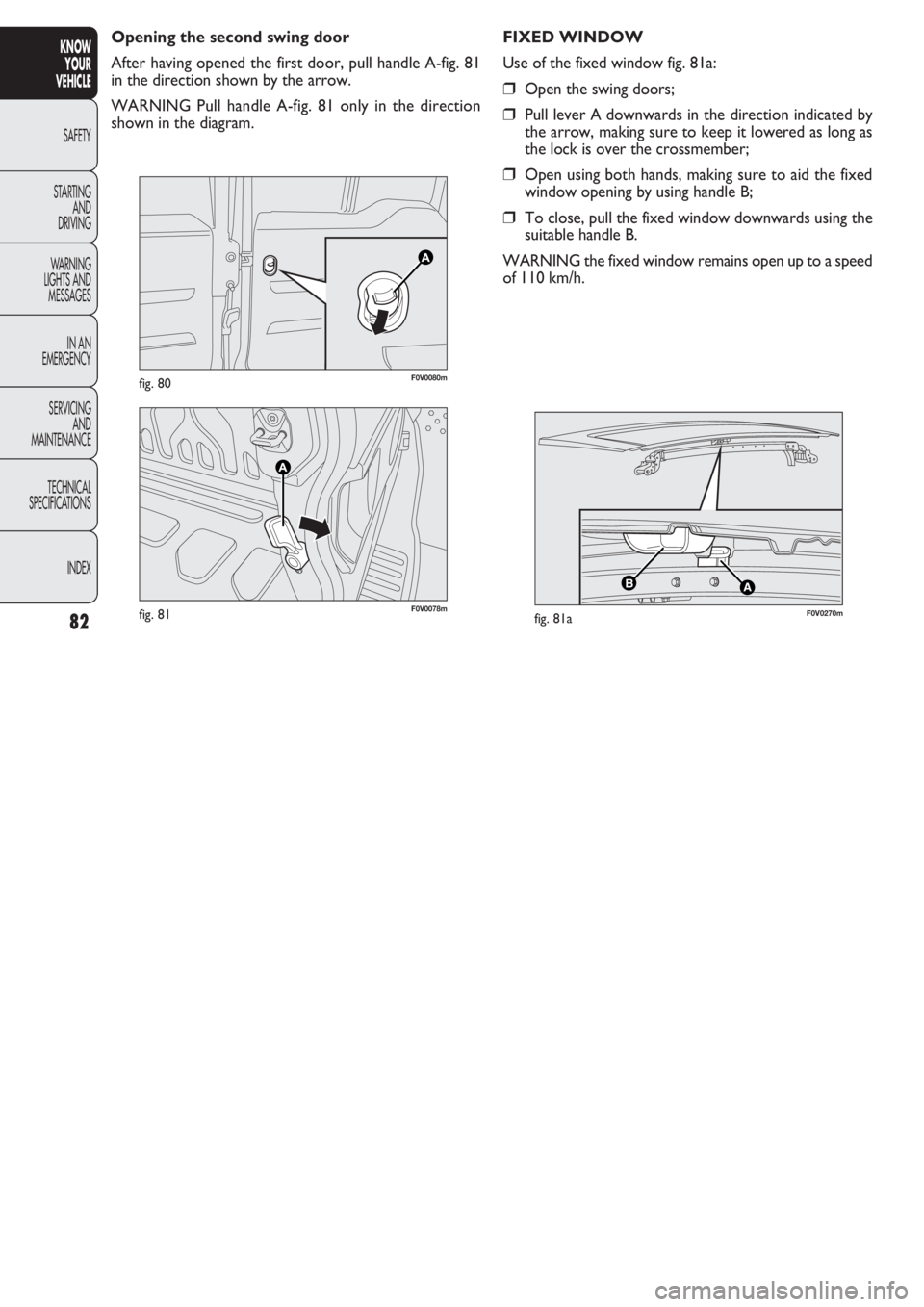
Opening the second swing door
After having opened the first door, pull handle A-fig. 81
in the direction shown by the arrow.
WARNING Pull handle A-fig. 81 only in the direction
shown in the diagram.
AB
F0V0270mfig. 81a
FIXED WINDOW
Use of the fixed window fig. 81a:
❒Open the swing doors;
❒Pull lever A downwards in the direction indicated by
the arrow, making sure to keep it lowered as long as
the lock is over the crossmember;
❒Open using both hands, making sure to aid the fixed
window opening by using handle B;
❒To close, pull the fixed window downwards using the
suitable handle B.
WARNING the fixed window remains open up to a speed
of 110 km/h.
Page 92 of 274
91
KNOW
YOUR
VEHICLE
SAFETY
STAR
TING
AND
DRIVING
WARNING
LIGHTS AND
MESSAGES
IN AN
EMERGENCY
SERVICING
AND
MAINTENANCE
TECHNICAL
SPECIFICATIONS
INDEX
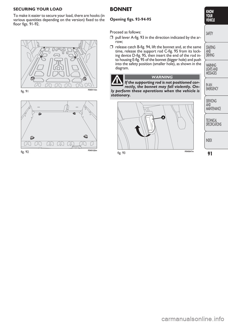
SECURING YOUR LOAD
To make it easier to secure your load, there are hooks (in
various quantities depending on the version) fixed to the
floor figs. 91-92.
F0V0047mfig. 93
BONNET
Opening figs. 93-94-95
Proceed as follows:
❒pull lever A-fig. 93 in the direction indicated by the ar-
row;
❒release catch B-fig. 94, lift the bonnet and, at the same
time, release the support rod C-fig. 95 from its lock-
ing device D-fig. 95, then insert the end of the rod in-
to housing E-fig. 95 of the bonnet (bigger hole) and push
into the safety position (smaller hole), as shown in the
diagram.
If the supporting rod is not positioned cor-
rectly, the bonnet may fall violently. On-
ly perform these operations when the vehicle is
stationary.
WARNING
F0V0122mfig. 92
F0V0114mfig. 91
Page 113 of 274
112
KNOW
YOUR
VEHICLE
SAFETY
STAR
TING
AND
DRIVING
WARNING
LIGHTS AND
MESSAGES
IN AN
EMERGENCY
SERVICING
AND
MAINTENANCE
TECHNICAL
SPECIFICATIONS
INDEX
F0V0086mfig. 109
REFUELLING CAPACITY
To fill the tank completely, top up twice after the pump
switches off. Further top ups could cause faults in the fu-
el supply system. If using/parking the vehicle in mountainous/cold areas for
a long time, you should refuel with locally available diesel.
In this case, it is also advisable to keep the tank over 50% full.
For diesel engines, use only diesel fuel for
motor vehicles in accordance with EN590
European specifications. The use of other
products or mixtures may damage the engine be-
yond repair and consequently invalidate the war-
ranty, depending on the damage caused. If you ac-
cidentally introduce other types of fuel into the
tank, do not start the engine. Empty the tank. If the
engine has run, even for a very short time, you will
need to have the entire fuel supply system emptied
in addition to the tank.
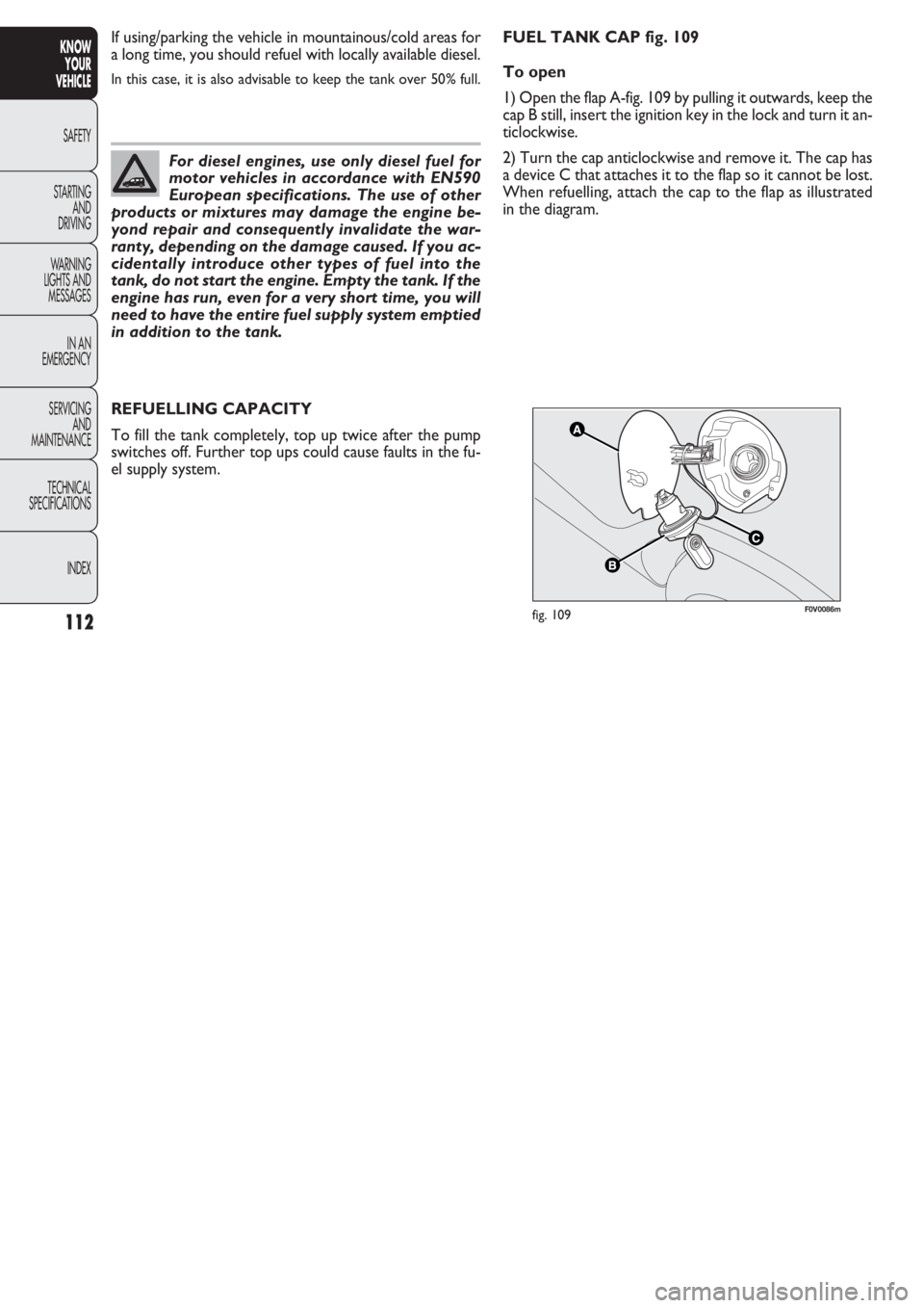
FUEL TANK CAP fig. 109
To open
1) Open the flap A-fig. 109 by pulling it outwards, keep the
cap B still, insert the ignition key in the lock and turn it an-
ticlockwise.
2) Turn the cap anticlockwise and remove it. The cap has
a device C that attaches it to the flap so it cannot be lost.
When refuelling, attach the cap to the flap as illustrated
in the diagram.
Page 123 of 274
122
KNOW
YOUR
VEHICLE
SAFETY
STARTING
AND
DRIVING
WARNING
LIGHTS AND
MESSAGES
IN AN
EMERGENCY
SERVICING
AND
MAINTENANCE
TECHNICAL
SPECIFICA
TIONS
INDEX
F0V0109mfig. 116F0V0196mfig. 117
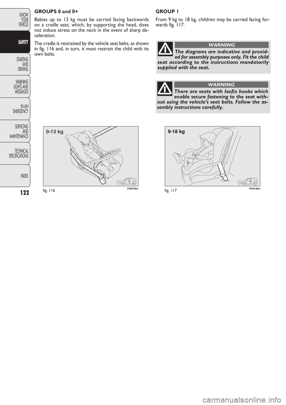
GROUP 1
From 9 kg to 18 kg, children may be carried facing for-
wards fig. 117. GROUPS 0 and 0+
Babies up to 13 kg must be carried facing backwards
on a cradle seat, which, by supporting the head, does
not induce stress on the neck in the event of sharp de-
celeration.
The cradle is restrained by the vehicle seat belts, as shown
in fig. 116 and, in turn, it must restrain the child with its
own belts.
The diagrams are indicative and provid-
ed for assembly purposes only. Fit the child
seat according to the instructions mandatorily
supplied with the seat.
WARNING
There are seats with Isofix hooks which
enable secure fastening to the seat with-
out using the vehicle’s seat belts. Follow the as-
sembly instructions carefully.
WARNING
Page 124 of 274
123
KNOW
YOUR
VEHICLE
SAFETY
STARTING
AND
DRIVING
WARNING
LIGHTS AND
MESSAGES
IN AN
EMERGENCY
SERVICING
AND
MAINTENANCE
TECHNICAL
SPECIFICA
TIONS
INDEX
F0V0111mfig. 118F0V0112mfig. 119
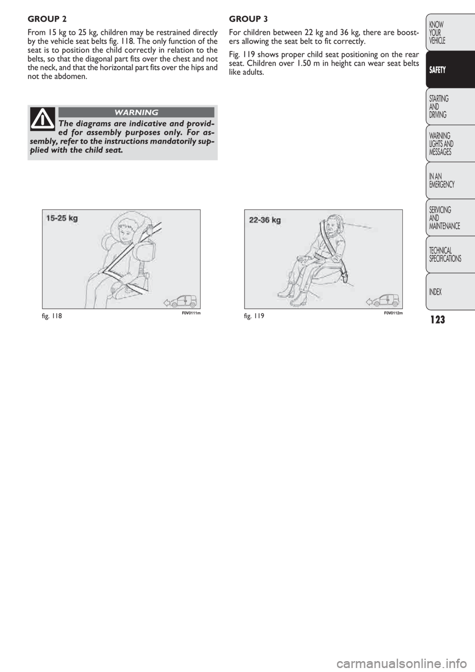
GROUP 3
For children between 22 kg and 36 kg, there are boost-
ers allowing the seat belt to fit correctly.
Fig. 119 shows proper child seat positioning on the rear
seat. Children over 1.50 m in height can wear seat belts
like adults. GROUP 2
From 15 kg to 25 kg, children may be restrained directly
by the vehicle seat belts fig. 118. The only function of the
seat is to position the child correctly in relation to the
belts, so that the diagonal part fits over the chest and not
the neck, and that the horizontal part fits over the hips and
not the abdomen.
The diagrams are indicative and provid-
ed for assembly purposes only. For as-
sembly, refer to the instructions mandatorily sup-
plied with the child seat.
WARNING
Page 137 of 274
136
KNOW
YOUR
VEHICLE
SAFETY
STARTING
AND
DRIVING
WARNING
LIGHTS AND
MESSAGES
IN AN
EMERGENCY
SERVICING
AND
MAINTENANCE
TECHNICAL
SPECIFICATIONS
INDEX
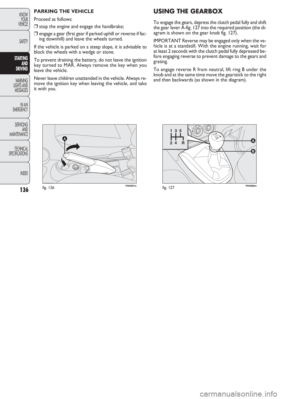
F0V0069mfig. 127F0V0087mfig. 126
PARKING THE VEHICLE
Proceed as follows:
❒stop the engine and engage the handbrake;
❒engage a gear (first gear if parked uphill or reverse if fac-
ing downhill) and leave the wheels turned.
If the vehicle is parked on a steep slope, it is advisable to
block the wheels with a wedge or stone.
To prevent draining the battery, do not leave the ignition
key turned to MAR. Always remove the key when you
leave the vehicle.
Never leave children unattended in the vehicle. Always re-
move the ignition key when leaving the vehicle, and take
it with you.
USING THE GEARBOX
To engage the gears, depress the clutch pedal fully and shift
the gear lever A-fig. 127 into the required position (the di-
agram is shown on the gear knob fig. 127).
IMPORTANT Reverse may be engaged only when the ve-
hicle is at a standstill. With the engine running, wait for
at least 2 seconds with the clutch pedal fully depressed be-
fore engaging reverse to prevent damage to the gears and
grating.
To engage reverse R from neutral, lift ring B under the
knob and at the same time move the gearstick to the right
and then backwards (as shown in the diagram).
Page 178 of 274
177
KNOW
YOUR
VEHICLE
SAFETY
STARTING
AND
DRIVING
WARNING
LIGHTS AND
MESSAGES
IN AN
EMERGENCY
SERVICING
AND
MAINTENANCE
TECHNICAL
SPECIFICATIONS
INDEX
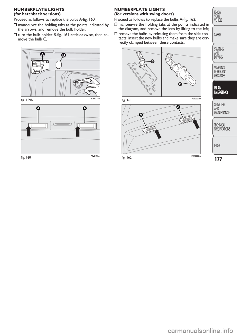
F0V0037mfig. 161
F0V0179mfig. 160
NUMBERPLATE LIGHTS
(for versions with swing doors)
Proceed as follows to replace the bulbs A-fig. 162:
❒manoeuvre the holding tabs at the points indicated in
the diagram, and remove the lens by lifting to the left;
❒remove the bulbs by releasing them from the side con-
tacts; insert the new bulbs and make sure they are cor-
rectly clamped between these contacts; NUMBERPLATE LIGHTS
(for hatchback versions)
Proceed as follows to replace the bulbs A-fig. 160:
❒manoeuvre the holding tabs at the points indicated by
the arrows, and remove the bulb holder;
❒turn the bulb holder B-fig. 161 anticlockwise, then re-
move the bulb C.
F0V0036mfig. 162
F0V0231mfig. 159b