FIAT DOBLO COMBI 2013 Owner handbook (in English)
Manufacturer: FIAT, Model Year: 2013, Model line: DOBLO COMBI, Model: FIAT DOBLO COMBI 2013Pages: 283, PDF Size: 6.31 MB
Page 31 of 283
27
KNOW
YOUR
VEHICLE
SAFETY
STAR
TING
AND
DRIVING
WARNING
LIGHTS AND
MESSAGES
IN AN
EMERGENCY
SERVICING
AND
MAINTENANCE
TECHNICAL
SPECIFICATIONS
INDEX
Daytime Running Lights (DRL)
This function allows you to activate/deactivate the daytime
running lights.
Proceed as follows to switch this function on or off:
– press the SET ESC button to display a submenu;
– press the SET ESC button again: the display flashes On
or Off depending on what was previously set;
–press▲ or▼to select;
– press the SET ESC button to return to the submenu
screen or hold the button down to return to the main
menu screen without saving;
– hold down SET ESC again to go back to the standard
screen or main menu, depending on which point in the
menu you have reached.
Exit menu
This function closes the settings listed on the menu screen.
Press SET ESC to go back to the standard screen with-
out saving.
Press ▼to return to the first menu option (Speed beep).
Activating/deactivating passenger front and side
airbags
(for versions/markets where provided)
This function is used to activate/deactivate the front and
side passenger airbags (for versions/markets where pro-
vided).
Proceed as follows:
– press SET ESC and, after the message Bag pass: Off (to
deactivate) or Bag pass On (to activate) is displayed by
pressing buttons
▲or ▼, press SET ESC again;
– the confirmation request message appears in the display;
– press ▲or ▼to select Yes (confirming activa-
tion/deactivation) or No (to cancel);
– press SET ESC to confirm the setting and go back to
the menu screen or hold the button down to go back to
the standard screen without saving.
Page 32 of 283
28
KNOWYOUR
VEHICLE
SAFETY
ST AR
TINGAND
DRIVING
WARNING
LIGHTS AND MESSAGES
IN AN
EMERGENCY
SERVICING AND
MAINTENANCE
TECHNICAL
SPECIFICATIONS
INDEX
Values displayed
Range
Shows the approximate distance the vehicle can travel with
the amount of fuel left in the tank. The display will show
the reading “----” when the following events take place:
– range is lower than 50 km (or 30 mi)
– vehicle is left parked with the engine running for a long
time.
WARNING The range can be affected by several factors:
driving style (see “Driving style” in the “Starting and dri-
ving” section), type of route (motorway, towns and cities,
mountain roads, etc.), conditions of use (load, tyre pres-
sures, etc.). Trip planning must therefore take the above
into account.
Distance travelled
Shows the distance covered since the start of the new jour-
ney.
Average consumption
Shows the approximate average fuel consumption since
the start of the new journey.
Current consumption
Shows the constantly updated fuel consumption. The read-
ing “----” appears on the display if the vehicle is parked with
the engine running.
Average speed
Shows the average speed of the vehicle by using the over-
all time elapsed since the start of a new journey.TRIP COMPUTER
General information
The Trip computer is used to display information on ve-
hicle operation when the ignition key is turned to MAR.
This function allows you to define two separate trips, called
“Trip A” and “Trip B”, for monitoring the vehicle’s „com-
plete mission” (journey) in a reciprocally independent man-
ner. Both functions can be reset (reset – start of a new
journey).
“Trip A” is used to display the figures relating to:
– Range
– Distance travelled
– Average consumption
– Instant consumption
– Average speed
– Travel time (driving time).
“Trip B”, available on multifunction display only, is used to
display the figures relating to:
– Distance travelled B
– Average consumption B
– Average speed B
– Travel time B (driving time).
N.B. “Trip B” may be disabled (see “Activating Trip B”).
“Range” and “Instant consumption” parameters cannot be
reset.
Page 33 of 283
29
KNOW
YOUR
VEHICLE
SAFETY
STAR
TING
AND
DRIVING
WARNING
LIGHTS AND
MESSAGES
IN AN
EMERGENCY
SERVICING
AND
MAINTENANCE
TECHNICAL
SPECIFICATIONS
INDEX
F0V0010mfig. 18
WARNING The reset operation when “Trip A” details
are being displayed only resets the information associat-
ed with this function.
WARNING The reset operation when “Trip B” details are
being displayed only resets the information associated with
this function.
Start trip procedure
With the ignition key at MAR, reset by pressing the TRIP
button and holding it down for more than two seconds.
Exit Trip
To quit the Trip function, hold down SET ESC for more
than two seconds.
Journey time
Shows the time elapsed since the start of a new journey.
WARNING If information is not available, the reading
“----” appears instead of the Trip computer values. Count-
ing the different values will resume regularly when normal
operation condition is restored. This will not reset any
of the values displayed before the failure or start a new
journey.
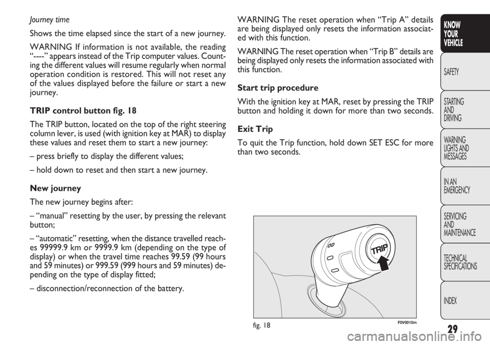
TRIP control button fig. 18
The TRIP button, located on the top of the right steering
column lever, is used (with ignition key at MAR) to display
these values and reset them to start a new journey:
– press briefly to display the different values;
– hold down to reset and then start a new journey.
New journey
The new journey begins after:
– “manual” resetting by the user, by pressing the relevant
button;
– “automatic” resetting, when the distance travelled reach-
es 99999.9 km or 9999.9 km (depending on the type of
display) or when the travel time reaches 99.59 (99 hours
and 59 minutes) or 999.59 (999 hours and 59 minutes) de-
pending on the type of display fitted;
– disconnection/reconnection of the battery.
Page 34 of 283
30
KNOWYOUR
VEHICLE
SAFETY
ST AR
TINGAND
DRIVING
WARNING
LIGHTS AND MESSAGES
IN AN
EMERGENCY
SERVICING AND
MAINTENANCE
TECHNICAL
SPECIFICATIONS
INDEX
Reclining backrest adjustment
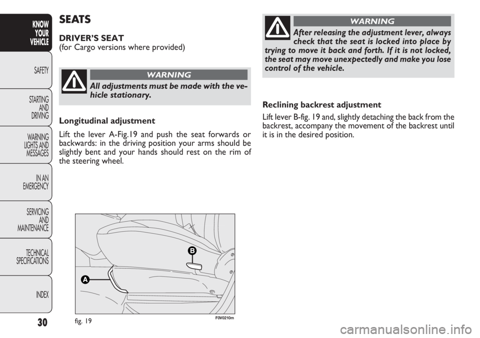
Lift lever B-fig. 19 and, slightly detaching the back from the
backrest, accompany the movement of the backrest until
it is in the desired position.
SEATS
DRIVER’S SEAT
(for Cargo versions where provided)
All adjustments must be made with the ve-
hicle stationary.
WARNING
After releasing the adjustment lever, always
check that the seat is locked into place by
trying to move it back and forth. If it is not locked,
the seat may move unexpectedly and make you lose
controlofthevehicle.
WARNING
Longitudinal adjustment
Lift the lever A-Fig.19 and push the seat forwards or
backwards: in the driving position your arms should be
slightly bent and your hands should rest on the rim of
the steering wheel.
fig. 19F0V0210m
Page 35 of 283
31
KNOW
YOUR
VEHICLE
SAFETY
STAR
TING
AND
DRIVING
WARNING
LIGHTS AND
MESSAGES
IN AN
EMERGENCY
SERVICING
AND
MAINTENANCE
TECHNICAL
SPECIFICATIONS
INDEX
WARNING Adjustment must only be carried out when
seated in the relevant seat.
Driver’s seat lumbar support adjustment
(for versions/markets where provided)
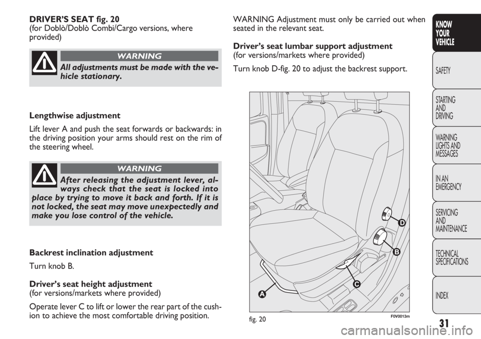
Turn knob D-fig. 20 to adjust the backrest support.
DRIVER’S SEAT fig. 20
(for Doblò/Doblò Combi/Cargo versions, where
provided)
F0V0013mfig. 20
All adjustments must be made with the ve-
hicle stationary.
WARNING
Lengthwise adjustment
Lift lever A and push the seat forwards or backwards: in
the driving position your arms should rest on the rim of
the steering wheel.
After releasing the adjustment lever, al-
ways check that the seat is locked into
place by trying to move it back and forth. If it is
not locked, the seat may move unexpectedly and
make you lose control of the vehicle.
WARNING
Backrest inclination adjustment
Turn knob B.
Driver’s seat height adjustment
(for versions/markets where provided)
Operate lever C to lift or lower the rear part of the cush-
ion to achieve the most comfortable driving position.
Page 36 of 283
32
KNOWYOUR
VEHICLE
SAFETY
ST AR
TINGAND
DRIVING
WARNING
LIGHTS AND MESSAGES
IN AN
EMERGENCY
SERVICING AND
MAINTENANCE
TECHNICAL
SPECIFICATIONS
INDEX
fig. 21F0V0142mfig. 22
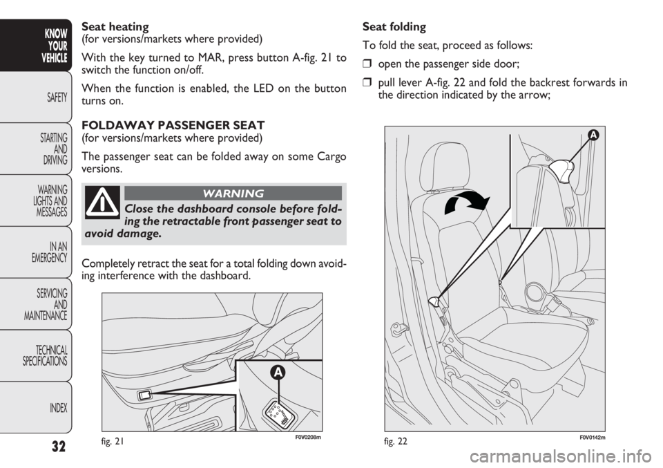
Seat folding
To fold the seat, proceed as follows:
❒open the passenger side door;
❒pull lever A-fig. 22 and fold the backrest forwards in
the direction indicated by the arrow;
Seat heating
(for versions/markets where provided)
With the key turned to MAR, press button A-fig. 21 to
switch the function on/off.
When the function is enabled, the LED on the button
turns on.
FOLDAWAY PASSENGER SEAT
(for versions/markets where provided)
The passenger seat can be folded away on some Cargo
versions.
F0V0208m
Close the dashboard console before fold-
ing the retractable front passenger seat to
avoid damage.
WARNING
Completely retract the seat for a total folding down avoid-
ing interference with the dashboard.
Page 37 of 283
33
KNOW
YOUR
VEHICLE
SAFETY
STAR
TING
AND
DRIVING
WARNING
LIGHTS AND
MESSAGES
IN AN
EMERGENCY
SERVICING
AND
MAINTENANCE
TECHNICAL
SPECIFICATIONS
INDEX
F0V0143mfig. 23
F0V0144mfig. 24
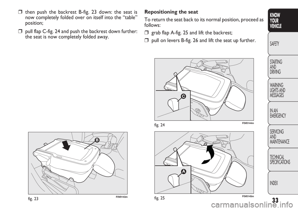
❒then push the backrest B-fig. 23 down: the seat is
now completely folded over on itself into the “table”
position;
❒pull flap C-fig. 24 and push the backrest down further:
the seat is now completely folded away. Repositioning the seat
To return the seat back to its normal position, proceed as
follows:❒grab flap A-fig. 25 and lift the backrest;
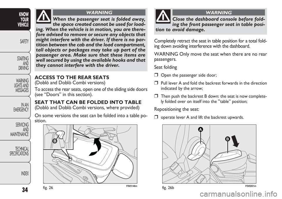
❒pull on levers B-fig. 26 and lift the seat up further.
F0V0145mfig. 25
Page 38 of 283
34
KNOWYOUR
VEHICLE
SAFETY
ST AR
TINGAND
DRIVING
WARNING
LIGHTS AND MESSAGES
IN AN
EMERGENCY
SERVICING AND
MAINTENANCE
TECHNICAL
SPECIFICATIONS
INDEX
F0V0146mfig. 26
When the passenger seat is folded away,
the space created cannot be used for load-
ing. When the vehicle is in motion, you are there-
fore advised to remove or secure any objects that
might interfere with the driver. If there is no par-
tition between the cab and the load compartment,
tall objects or packages may take up part of the
passenger area. Make sure that these items are
well secured by using the available hooks and that
they cannot interfere with the driver.
WARNING
ACCESS TO THE REAR SEATS
(Doblò and Doblò Combi versions)
To access the rear seats, open one of the sliding side doors
(see “Doors” in this section).
SEAT THAT CAN BE FOLDED INTO TABLE
(Doblò and Doblò Combi versions, where provided)
On some versions the seat can be folded into a table po-
sition. Completely retract the seat in table position for a total fold-
ing down avoiding interference with the dashboard.
WARNING Only move the seat when there are no rear
passengers.
Seat folding❒Open the passenger side door;
❒Pull lever A and fold the backrest forwards in the direction
indicated by the arrow;
❒Then push the backrest B down: the seat is now complete-
ly folded over on itself into the
“table” position;
Repositioning the seat:
❒operate lever A and lift the backrest upwards.
F0V0201mfig. 26b
Close the dashboard console before fold-
ing the front passenger seat in table posi-
tion to avoid damage.
WARNING
Page 39 of 283
35
KNOW
YOUR
VEHICLE
SAFETY
STAR
TING
AND
DRIVING
WARNING
LIGHTS AND
MESSAGES
IN AN
EMERGENCY
SERVICING
AND
MAINTENANCE
TECHNICAL
SPECIFICATIONS
INDEX
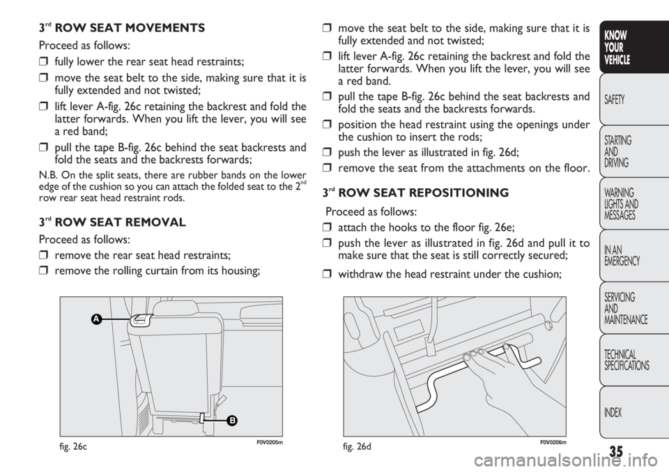
3rdROW SEAT MOVEMENTS
Proceed as follows:
❒fully lower the rear seat head restraints;
❒move the seat belt to the side, making sure that it is
fully extended and not twisted;
❒lift lever A-fig. 26c retaining the backrest and fold the
latter forwards. When you lift the lever, you will see
a red band;
❒pull the tape B-fig. 26c behind the seat backrests and
fold the seats and the backrests forwards;
N.B. On the split seats, there are rubber bands on the lower
edge of the cushion so you can attach the folded seat to the 2nd
row rear seat head restraint rods.
3rdROW SEAT REMOVAL
Proceed as follows:
❒remove the rear seat head restraints;
❒remove the rolling curtain from its housing;
❒move the seat belt to the side, making sure that it is
fully extended and not twisted;
❒lift lever A-fig. 26c retaining the backrest and fold the
latter forwards. When you lift the lever, you will see
a red band.
❒pull the tape B-fig. 26c behind the seat backrests and
fold the seats and the backrests forwards.
❒position the head restraint using the openings under
the cushion to insert the rods;
❒push the lever as illustrated in fig. 26d;
❒remove the seat from the attachments on the floor.
3
rdROW SEAT REPOSITIONING
Proceed as follows:
❒attach the hooks to the floor fig. 26e;
❒push the lever as illustrated in fig. 26d and pull it to
make sure that the seat is still correctly secured;
❒withdraw the head restraint under the cushion;
B
A
F0V0205mfig. 26cF0V0206mfig. 26d
Page 40 of 283
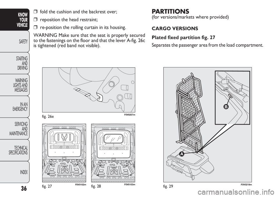
PARTITIONS
(for versions/markets where provided)
CARGO VERSIONS
Plated fixed partition fig. 27
Separates the passenger area from the load compartment.
36
KNOWYOUR
VEHICLE
SAFETY
ST AR
TING AND
DRIVING
WARNING
LIGHTS AND MESSAGES
IN AN
EMERGENCY
SERVICING AND
MAINTENANCE
TECHNICAL
SPECIFICATIONS
INDEX
❒fold the cushion and the backrest over;
❒reposition the head restraint;
❒re-position the rolling curtain in its housing.
WARNING Make sure that the seat is properly secured
to the fastenings on the floor and that the lever A-fig. 26c
is tightened (red band not visible).
F0V0219mfig. 29F0V0103mfig. 28F0V0102mfig. 27
F0V0207mfig. 26e