FIAT DOBLO COMBI 2013 Owner handbook (in English)
Manufacturer: FIAT, Model Year: 2013, Model line: DOBLO COMBI, Model: FIAT DOBLO COMBI 2013Pages: 283, PDF Size: 6.31 MB
Page 11 of 283
7
KNOW
YOUR
VEHICLE
SAFETY
STAR
TING
AND
DRIVING
WARNING
LIGHTS AND
MESSAGES
IN AN
EMERGENCY
SERVICING
AND
MAINTENANCE
TECHNICAL
SPECIFICATIONS
INDEX
F0V0022mfig. 5F0V0005mfig. 6
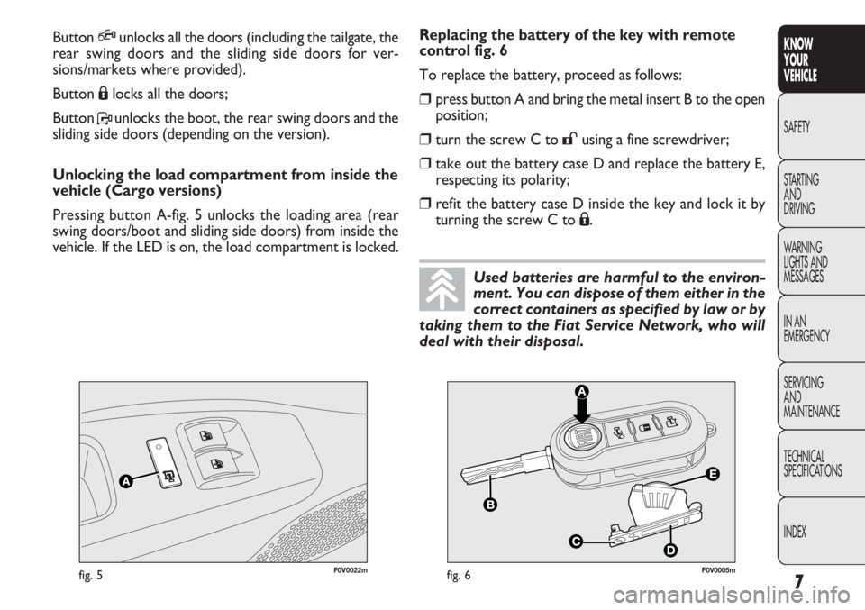
Replacing the battery of the key with remote
control fig. 6
To replace the battery, proceed as follows:
❒press button A and bring the metal insert B to the open
position;
❒turn the screw C to:using a fine screwdriver;
❒take out the battery case D and replace the battery E,
respecting its polarity;
❒refit the battery case D inside the key and lock it by
turning the screw C to
Á.
Button
Qunlocks all the doors (including the tailgate, the
rear swing doors and the sliding side doors for ver-
sions/markets where provided).
Button Álocks all the doors;
Button Punlocks the boot, the rear swing doors and the
sliding side doors (depending on the version).
Unlocking the load compartment from inside the
vehicle (Cargo versions)
Pressing button A-fig. 5 unlocks the loading area (rear
swing doors/boot and sliding side doors) from inside the
vehicle. If the LED is on, the load compartment is locked.
Used batteries are harmful to the environ-
ment. You can dispose of them either in the
correct containers as specified by law or by
taking them to the Fiat Service Network, who will
deal with their disposal.
Page 12 of 283
Switching the device on
The system is automatically enabled on all the doors by
pressing button
Átwice on the key with remote control.
The direction indicators flash twice to let you know that
the device is active.
If one or more of the doors is not perfectly shut, the dead
lock device will not be activated, thus preventing a person
getting into the vehicle through the open door and, on
shutting, it, remaining stuck inside the passenger com-
partment.
Switching the device off
The system is disabled automatically on every door when:
❒unlocking the doors;
❒turning the ignition key to MAR.
Requesting additional remote controls
The system acknowledges up to 8 remote controls. Should
a new remote control be necessary, contact the Fiat Ser-
vice Network and be ready to present the CODE card, a
personal identity document and the vehicle ownership doc-
uments.
DEAD LOCK
(for versions/markets where provided)
This safety device prevents the opening of the doors from
inside the passenger compartment if there has been a break
in attempt (e.g. a window has been broken).
The dead lock device therefore offers the best possible
protection against break in attempts. We recommend en-
gaging it whenever the vehicle is parked and left unat-
tended.
8
KNOW
YOUR
VEHICLE
SAFETY
ST AR
TINGAND
DRIVING
WARNING
LIGHTS AND MESSAGES
IN AN
EMERGENCY
SERVICING AND
MAINTENANCE
TECHNICAL
SPECIFICATIONS
INDEX
Once the dead lock system is engaged it is
impossible to open the doors from inside
the vehicle. Before engaging the system please
therefore check that there is no one left on board.
WARNING
If the remote control battery is flat, the
system can only be turned on by inserting
the metal key in the door lock: in this case, the de-
vice remains active for the rear doors only.
WARNING
Page 13 of 283
9
KNOW
YOUR
VEHICLE
SAFETY
STAR
TING
AND
DRIVING
WARNING
LIGHTS AND
MESSAGES
IN AN
EMERGENCY
SERVICING
AND
MAINTENANCE
TECHNICAL
SPECIFICATIONS
INDEX
STARTING DEVICE
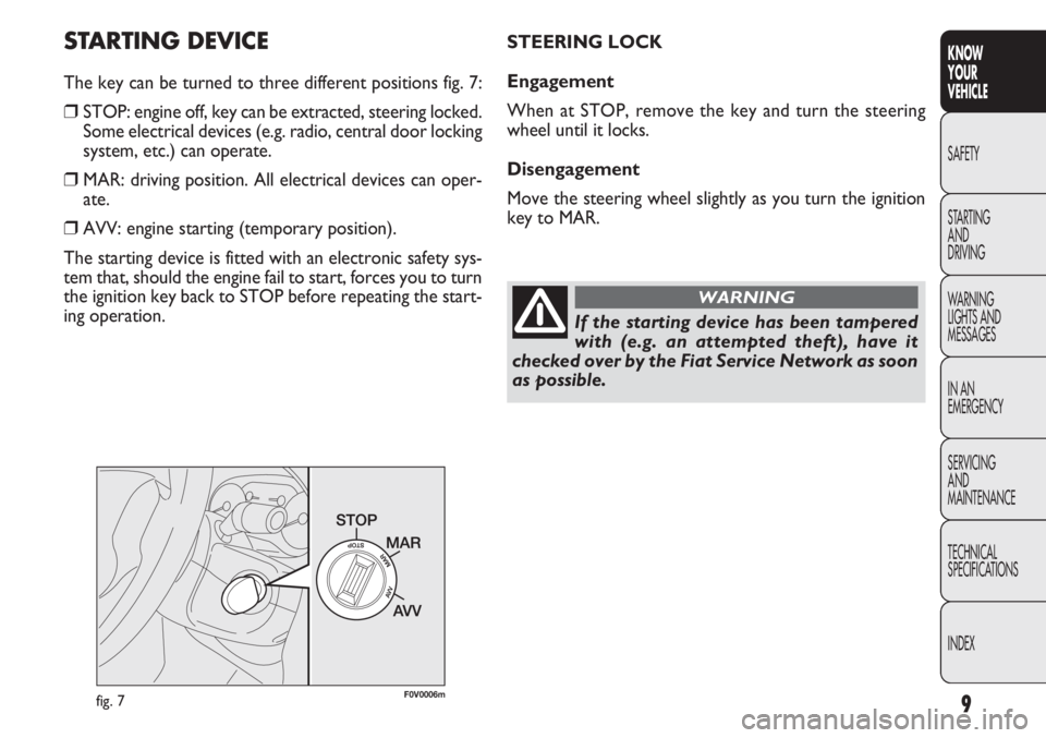
The key can be turned to three different positions fig. 7:
❒STOP: engine off, key can be extracted, steering locked.
Some electrical devices (e.g. radio, central door locking
system, etc.) can operate.
❒MAR: driving position. All electrical devices can oper-
ate.
❒AVV: engine starting (temporary position).
The starting device is fitted with an electronic safety sys-
tem that, should the engine fail to start, forces you to turn
the ignition key back to STOP before repeating the start-
ing operation.
F0V0006mfig. 7
STEERING LOCK
Engagement
When at STOP, remove the key and turn the steering
wheel until it locks.
Disengagement
Move the steering wheel slightly as you turn the ignition
key to MAR.
If the starting device has been tampered
with (e.g. an attempted theft), have it
checked over by the Fiat Service Network as soon
as possible.
WARNING
Page 14 of 283
10
KNOWYOUR
VEHICLE
SAFETY
ST AR
TINGAND
DRIVING
WARNING
LIGHTS AND MESSAGES
IN AN
EMERGENCY
SERVICING AND
MAINTENANCE
TECHNICAL
SPECIFICATIONS
INDEX
Never extract the key while the vehicle is
moving. The steering wheel should lock au-
tomatically as soon as it is turned. This is always
the case, even when the vehicle is being towed.
WARNING
It is absolutely forbidden to carry out any
aftersales operation involving steering sys-
tem or steering column modifications (e.g. installing
an anti-theft device) that could badly affect per-
formance and safety, invalidate the warranty and
also result in the vehicle failing to comply with reg-
ulations.
WARNING
When getting out of the vehicle, always re-
move the key to prevent someone from
accidentally activating the controls. Remember to
engage the handbrake. Engage first gear if the ve-
hicle is parked uphill or reverse gear if the vehi-
cle is parked downhill. Never leave children un-
attended in the vehicle.
WARNING
Page 15 of 283
11
KNOW
YOUR
VEHICLE
SAFETY
STAR
TING
AND
DRIVING
WARNING
LIGHTS AND
MESSAGES
IN AN
EMERGENCY
SERVICING
AND
MAINTENANCE
TECHNICAL
SPECIFICATIONS
INDEX
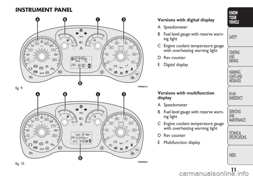
INSTRUMENT PANEL
Versions with digital display
A Speedometer
B Fuel level gauge with reserve warn-
ing light
C Engine coolant temperature gauge with overheating warning light
D Rev counter
E Digital display
Versions with multifunction
display
A Speedometer
B Fuel level gauge with reserve warn- ing light
C Engine coolant temperature gauge with overheating warning light
D Rev counter
E Multifunction display
F0V0001mfig. 9
F0V0002mfig. 10
Page 16 of 283
12
KNOWYOUR
VEHICLE
SAFETY
ST AR
TINGAND
DRIVING
WARNING
LIGHTS AND MESSAGES
IN AN
EMERGENCY
SERVICING AND
MAINTENANCE
TECHNICAL
SPECIFICATIONS
INDEX
F0V0007mfig. 11F0V0008mfig. 12
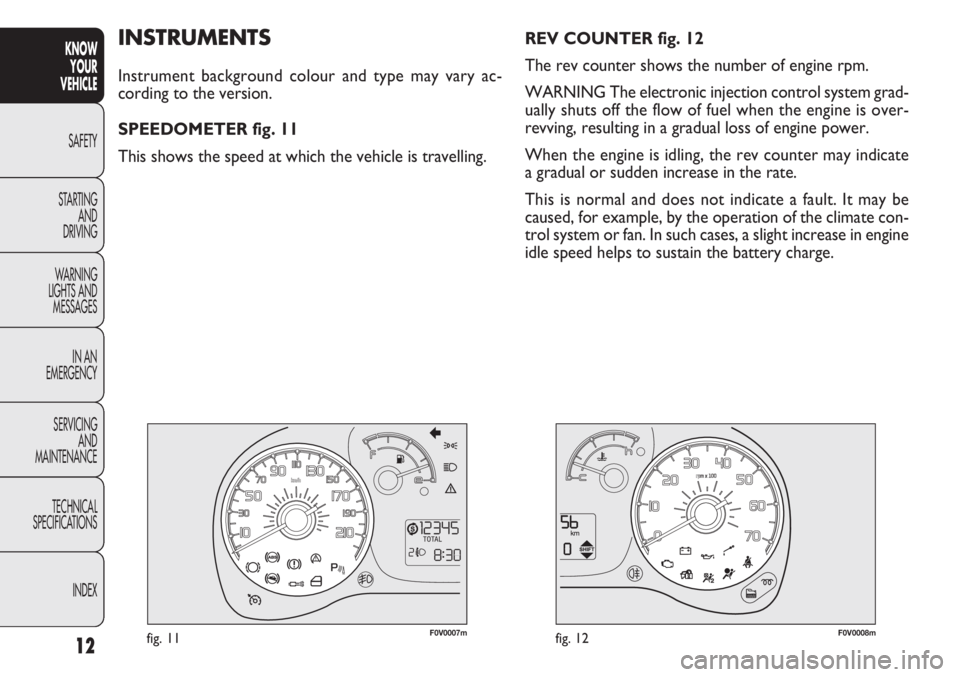
REV COUNTER fig. 12
The rev counter shows the number of engine rpm.
WARNING The electronic injection control system grad-
ually shuts off the flow of fuel when the engine is over-
revving, resulting in a gradual loss of engine power.
When the engine is idling, the rev counter may indicate
a gradual or sudden increase in the rate.
This is normal and does not indicate a fault. It may be
caused, for example, by the operation of the climate con-
trol system or fan. In such cases, a slight increase in engine
idle speed helps to sustain the battery charge.INSTRUMENTS
Instrument background colour and type may vary ac-
cording to the version.
SPEEDOMETER fig. 11
This shows the speed at which the vehicle is travelling.
Page 17 of 283
13
KNOW
YOUR
VEHICLE
SAFETY
STAR
TING
AND
DRIVING
WARNING
LIGHTS AND
MESSAGES
IN AN
EMERGENCY
SERVICING
AND
MAINTENANCE
TECHNICAL
SPECIFICATIONS
INDEX
F0V0009mfig. 13
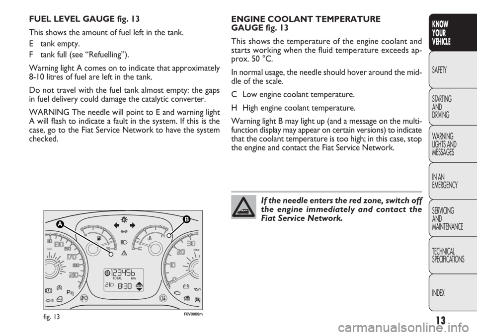
ENGINE COOLANT TEMPERATURE
GAUGE fig. 13
This shows the temperature of the engine coolant and
starts working when the fluid temperature exceeds ap-
prox. 50 °C.
In normal usage, the needle should hover around the mid-
dleofthescale.
C Low engine coolant temperature.
H High engine coolant temperature.
Warning light B may light up (and a message on the multi-
function display may appear on certain versions) to indicate
that the coolant temperature is too high; in this case, stop
the engine and contact the Fiat Service Network.
FUEL LEVEL GAUGE fig. 13
This shows the amount of fuel left in the tank.
E tank empty.
F tank full (see “Refuelling”).
Warning light A comes on to indicate that approximately
8-10 litres of fuel are left in the tank.
Do not travel with the fuel tank almost empty: the gaps
in fuel delivery could damage the catalytic converter.
WARNING The needle will point to E and warning light
A will flash to indicate a fault in the system. If this is the
case, go to the Fiat Service Network to have the system
checked.
If the needle enters the red zone, switch off
the engine immediately and contact the
Fiat Service Network.
Page 18 of 283
14
KNOWYOUR
VEHICLE
SAFETY
ST AR
TINGAND
DRIVING
WARNING
LIGHTS AND MESSAGES
IN AN
EMERGENCY
SERVICING AND
MAINTENANCE
TECHNICAL
SPECIFICATIONS
INDEX
DIGITAL DISPLAY
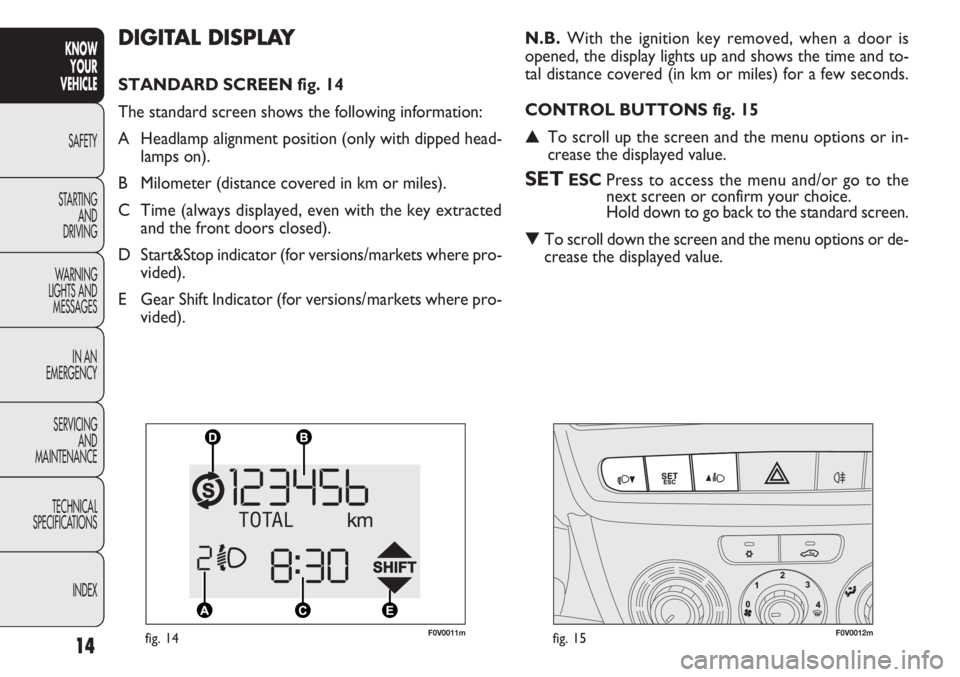
STANDARD SCREEN fig. 14
The standard screen shows the following information:
A Headlamp alignment position (only with dipped head-lamps on).
B Milometer (distance covered in km or miles).
C Time (always displayed, even with the key extracted and the front doors closed).
D Start&Stop indicator (for versions/markets where pro- vided).
E Gear Shift Indicator (for versions/markets where pro- vided). N.B.
With the ignition key removed, when a door is
opened, the display lights up and shows the time and to-
tal distance covered (in km or miles) for a few seconds.
CONTROL BUTTONS fig. 15
▲ To scroll up the screen and the menu options or in-
crease the displayed value.
SETESC Press to access the menu and/or go to the
next screen or confirm your choice.
Hold down to go back to the standard screen.
▼ To scroll down the screen and the menu options or de-
crease the displayed value.
F0V0011mfig. 14F0V0012mfig. 15
Page 19 of 283
15
KNOW
YOUR
VEHICLE
SAFETY
STAR
TING
AND
DRIVING
WARNING
LIGHTS AND
MESSAGES
IN AN
EMERGENCY
SERVICING
AND
MAINTENANCE
TECHNICAL
SPECIFICATIONS
INDEX
N.B. Buttons ▲and ▼activate different functions in the
following situations:
– within the menu, they scroll up and down;
– during setting operations they increase or decrease the
value.
SETUP MENU
The menu comprises a series of functions arranged in
a circle which can be selected through buttons ▲and ▼
to access the settings described below.
The setup menu can be activated by pressing the SET ESC
button.
By pressing buttons ▲and ▼you can scroll through the
setup menu options.
Management modes differ from each other according to
the option selected.
The menu comprises the following functions:
– ILLU
– SPEED
–HOUR
– UNIT
–BUZZ
– BAG P
– DRL Selecting a menu option
– press the SET ESC button to select the menu option
to set;
– press buttons
▲and ▼to select the new setting;
– press the SET ESC button to memorize the new set-
ting and go back to the previous menu option.
Selecting “Set clock”
– press the SET ESC button to select the first value to
change (hours);
– press buttons ▲and ▼to select the new setting;
– press the SET ESC button to memorize the new set-
ting and go to the next value (minutes);
– after setting the value with the same procedure, you go
back to the previous menu item.
Page 20 of 283
Proceed as follows to adjust the brightness:
– press the SET ESC button: the display will show ILLU;
– press button▲or ▼to adjust the brightness level;
– press the SET ESC button to go back to the menu screen
or hold the button down to go back to the standard screen
without saving.
Setting the speed limit (SPEEd)
This function is used to set a speed limit (km/h or mph);
the driver is alerted when this limit is exceeded (see
“Warning lights and messages”).
To set the desired speed limit, proceed as follows:
– press SET ESC: the word SPEEd and the previously set
unit (km/h or mph) will appear on the display;
– press button ▲or ▼to select speed limit activation (On)
or deactivation (Off);
– when the function is activated (On), press buttons
▲ or ▼to select the speed limit and press SET ESC to
confirm.
Hold down the SET ESC button
– to quit the setup menu if you are in the menu;
– to quit to the menu if you are setting an option;
– to save only the settings already memorized (confirmed
by pressing the SET ESC button).
The setup menu page is timed. Only the changes already
memorized by pressing the SET ESC button are saved
when you come out of the menu.
Adjusting the vehicle interior lighting
(ILLU)
This function is available, with the dipped headlamps on
and at night, to adjust the brightness of the instrument pan-
el, buttons, radio display and automatic climate control dis-
play.
During the daytime, and with the dipped headlamps on,
the instrument panel, buttons and radio and automatic cli-
mate control displays are set to maximum brightness.
16
KNOW
YOUR
VEHICLE
SAFETY
ST AR
TINGAND
DRIVING
WARNING
LIGHTS AND MESSAGES
IN AN
EMERGENCY
SERVICING AND
MAINTENANCE
TECHNICAL
SPECIFICATIONS
INDEX