clock FIAT DOBLO COMBI 2017 2.G Owners Manual
[x] Cancel search | Manufacturer: FIAT, Model Year: 2017, Model line: DOBLO COMBI, Model: FIAT DOBLO COMBI 2017 2.GPages: 300, PDF Size: 24.91 MB
Page 22 of 300
Each time the ignition key is turned to
STOP, the Fiat CODE system
deactivates the functions of the
Powertrain Control Module.
Irregular operation
If, during starting, the code has not
been recognised correctly the warning
light
on the instrument panel turns
on accompanied by the related
message on the display (see section
“Warning lights and messages”).
In this case, turn the key toSTOPand
then back toMAR; if the lock
continues, try with the other keys
provided with the vehicle. Contact a
Fiat Dealership if you still cannot start
the engine.
IMPORTANT Each key has its own
code which must be stored by the
system's control unit. Contact a Fiat
Dealership to have new keys (up to 8)
stored with a code.
Activation of
warning
light while driving
If the warning lightswitches on,
this means that the system is running
a self-diagnosis (for example due to
a voltage drop).
If the warning lightstays on,
contact a Fiat Dealership.
WARNING
1)The electronic components inside the
key may be damaged if the key is
subjected to strong shocks. In order to
ensure complete efficiency of the
electronic devices inside the key, it should
never be exposed to direct sunlight.
DOORS
DOOR CENTRAL
LOCKING/UNLOCKING
Locking doors from the outside
The doors will only be locked if all doors
are shut. If one or more of the doors is
open after button
is pressed on
the remote control, the direction
indicators will flash quickly for around
three seconds.
You can lock all the doors by turning
the key clockwise in the driver's door.
Pressing button
on the remote
control twice in quick succession
activates the dead lock device (see
"Dead lock").
Door unlocking from the outside
Press the
button shortly to remotely
unlock only the front doors (Cargo
version), to turn on the front ceiling
lights for a limited period and to double
flash the direction indicators.
Press the
button shortly to remotely
unlock the load compartment (Cargo
version), to turn on the rear ceiling lights
for a limited period and to double flash
the direction indicators. Turn the key
anticlockwise in the driver's door to
unlock the front doors only.
18
KNOWING YOUR VEHICLE
Page 23 of 300
Press thebutton briefly to unlock all
the doors (Doblò/Doblò Combi
version), switch on the roof lights
temporarily and double-flash the
direction indicators. Turn the key
anticlockwise in the driver's door to
unlock all the doors.
Unlocking the load compartment
from inside the vehicle (Cargo
version)
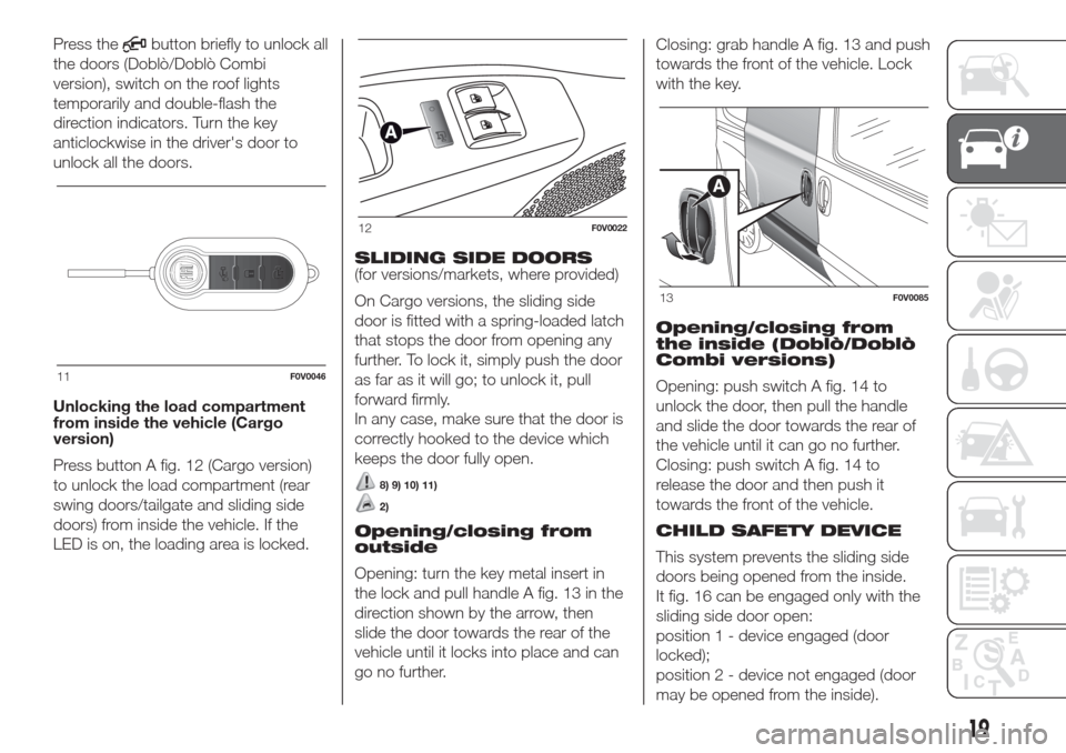
Press button A fig. 12 (Cargo version)
to unlock the load compartment (rear
swing doors/tailgate and sliding side
doors) from inside the vehicle. If the
LED is on, the loading area is locked.SLIDING SIDE DOORS
(for versions/markets, where provided)
On Cargo versions, the sliding side
door is fitted with a spring-loaded latch
that stops the door from opening any
further. To lock it, simply push the door
as far as it will go; to unlock it, pull
forward firmly.
In any case, make sure that the door is
correctly hooked to the device which
keeps the door fully open.
8) 9) 10) 11)
2)
Opening/closing from
outside
Opening: turn the key metal insert in
the lock and pull handle A fig. 13 in the
direction shown by the arrow, then
slide the door towards the rear of the
vehicle until it locks into place and can
go no further.Closing: grab handle A fig. 13 and push
towards the front of the vehicle. Lock
with the key.
Opening/closing from
the inside (Doblò/Doblò
Combi versions)
Opening: push switch A fig. 14 to
unlock the door, then pull the handle
and slide the door towards the rear of
the vehicle until it can go no further.
Closing: push switch A fig. 14 to
release the door and then push it
towards the front of the vehicle.
CHILD SAFETY DEVICE
This system prevents the sliding side
doors being opened from the inside.
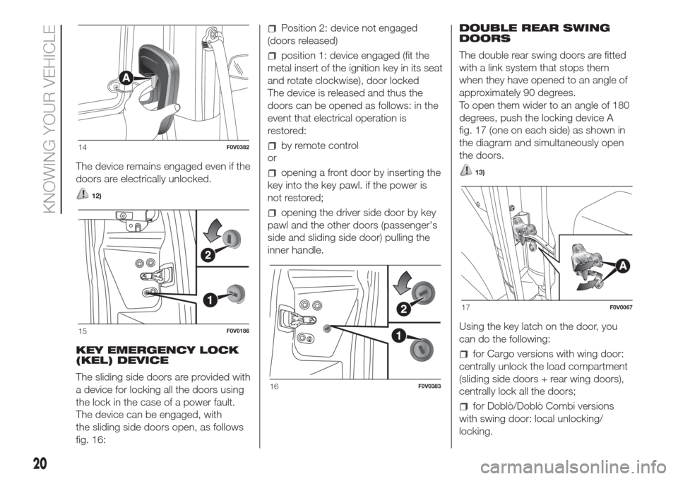
It fig. 16 can be engaged only with the
sliding side door open:
position 1 - device engaged (door
locked);
position 2 - device not engaged (door
may be opened from the inside).
11F0V0046
12F0V0022
13F0V0085
19
Page 24 of 300
The device remains engaged even if the
doors are electrically unlocked.
12)
KEY EMERGENCY LOCK
(KEL) DEVICE
The sliding side doors are provided with
a device for locking all the doors using
the lock in the case of a power fault.
The device can be engaged, with
the sliding side doors open, as follows
fig. 16:
Position 2: device not engaged
(doors released)
position 1: device engaged (fit the
metal insert of the ignition key in its seat
and rotate clockwise), door locked
The device is released and thus the
doors can be opened as follows: in the
event that electrical operation is
restored:
by remote control
or
opening a front door by inserting the
key into the key pawl. if the power is
not restored;
opening the driver side door by key
pawl and the other doors (passenger's
side and sliding side door) pulling the
inner handle.DOUBLE REAR SWING
DOORS
The double rear swing doors are fitted
with a link system that stops them
when they have opened to an angle of
approximately 90 degrees.
To open them wider to an angle of 180
degrees, push the locking device A
fig. 17 (one on each side) as shown in
the diagram and simultaneously open
the doors.
13)
Using the key latch on the door, you
can do the following:
for Cargo versions with wing door:
centrally unlock the load compartment
(sliding side doors + rear wing doors),
centrally lock all the doors;
for Doblò/Doblò Combi versions
with swing door: local unlocking/
locking.
14F0V0382
15F0V0186
16F0V0383
17F0V0067
20
KNOWING YOUR VEHICLE
Page 29 of 300
3RD ROW SEAT
MOVEMENTS
Proceed as follows:
completely lower the rear seat head
restraints;
move the seat belt to the side,
making sure that it is fully extended and
not twisted;
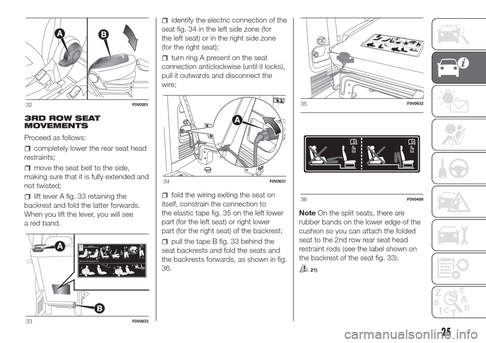
lift lever A fig. 33 retaining the
backrest and fold the latter forwards.
When you lift the lever, you will see
a red band.
identify the electric connection of the
seat fig. 34 in the left side zone (for
the left seat) or in the right side zone
(for the right seat);
turn ring A present on the seat
connection anticlockwise (until it locks),
pull it outwards and disconnect the
wire;
fold the wiring exiting the seat on
itself, constrain the connection to
the elastic tape fig. 35 on the left lower
part (for the left seat) or right lower
part (for the right seat) of the backrest;
pull the tape B fig. 33 behind the
seat backrests and fold the seats and
the backrests forwards, as shown in fig.
36.NoteOn the split seats, there are
rubber bands on the lower edge of the
cushion so you can attach the folded
seat to the 2nd row rear seat head
restraint rods (see the label shown on
the backrest of the seat fig. 33).
21)
32F0V0201
33F0V0633
34F0V0631
35F0V0632
36F0V0408
25
Page 30 of 300
REMOVING 3RD ROW
SEATS
Proceed as follows:
remove the rear seat head restraints;
remove the rolling curtain from its
housing;
move the seat belt to the side,
making sure that it is fully extended and
not twisted;
lift lever A fig. 33 retaining the
backrest and fold the latter forwards.
When you lift the lever, you will see
a red band.
identify the electric connection of the
seat fig. 34 connected to the vehicle in
the left side zone (for the left seat) or
in the right side zone (for the right seat);
turn ring A present on the seat
connection anticlockwise (until it locks),
pull it towards yourself and disconnect
the wire;
fold the wiring exiting the seat on
itself, constrain the connection to
the elastic tape fig. 35 present on the
seat backrest on the left lower part (for
the left seat) or right lower part (for
the right seat);
pull the tape B fig. 33 behind the
seat backrests and fold the seats and
the backrests forwards;
position the head restraint using the
openings under the cushion to insert
the rods;
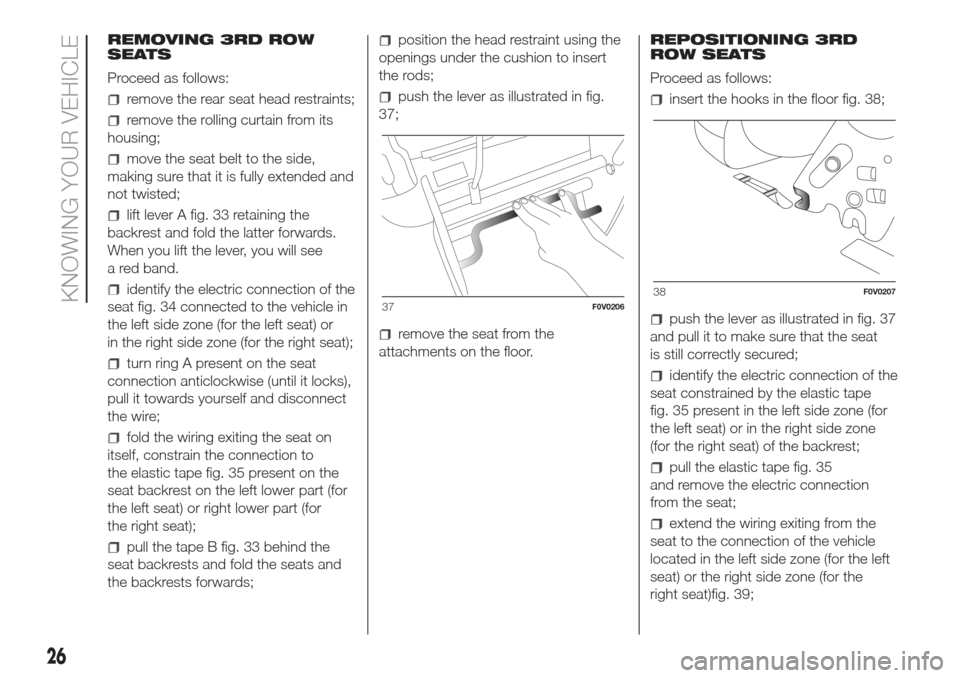
push the lever as illustrated in fig.
37;
remove the seat from the
attachments on the floor.REPOSITIONING 3RD
ROW SEATS
Proceed as follows:
insert the hooks in the floor fig. 38;
push the lever as illustrated in fig. 37
and pull it to make sure that the seat
is still correctly secured;
identify the electric connection of the
seat constrained by the elastic tape
fig. 35 present in the left side zone (for
the left seat) or in the right side zone
(for the right seat) of the backrest;
pull the elastic tape fig. 35
and remove the electric connection
from the seat;
extend the wiring exiting from the
seat to the connection of the vehicle
located in the left side zone (for the left
seat) or the right side zone (for the
right seat)fig. 39;
37F0V020638F0V0207
26
KNOWING YOUR VEHICLE
Page 31 of 300
connect the connection of the seat
A to the connection on vehicle and turn
the ring present on the seat connection
clockwise (until it locks);
withdraw the head restraint under
the cushion;
fold the cushion and the backrest
over;
reposition the head restraint;
reposition the rolling curtain in its
housing.
IMPORTANT Make sure that the seat is
properly secured to the fastenings on
the floor and that the lever A fig. 33
is tightened (red band not visible).FRONT BENCH
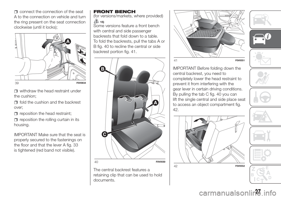
(for versions/markets, where provided)
15)Some versions feature a front bench
with central and side passenger
backrests that fold down to a table.
To fold the backrests, pull the tabs A or
B fig. 40 to recline the central or side
backrest portion fig. 41.
The central backrest features a
retaining clip that can be used to hold
documents.IMPORTANT Before folding down the
central backrest, you need to
completely lower the head restraint to
prevent it from interfering with the
gear lever in certain driving conditions.
By pulling the tab C fig. 40 you can
lift the single central and side place seat
to access an object compartment fig.
42.
39F0V0634
40F0V0550
41F0V0551
42F0V0552
27
Page 33 of 300
from inside the load compartment,
rotate the locking hook, remove the
panel, releasing it from the 4 passenger
side pins, and fit the panel on the
driver’s side pins B, then rotate locking
hook A.
To put the partition back in its normal
position, follow the same procedure
in reverse.DRIVER’S SIDE TUBULAR
PARTITION
(for versions with 3-seater bench)
On versions with 3-seater bench there
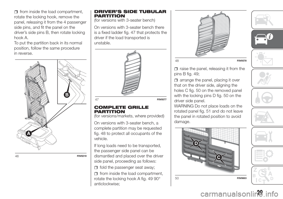
is a fixed ladder fig. 47 that protects the
driver if the load transported is
unstable.
COMPLETE GRILLE
PARTITION
(for versions/markets, where provided)
On versions with 3-seater bench, a
complete partition may be requested
fig. 48 to protect all occupants of the
vehicle.
If long loads need to be transported,
the passenger side panel can be
dismantled and placed over the driver
side panel, proceeding as follows:
fold the passenger seat away;
from inside the load compartment,
rotate the locking hook A fig. 49 90°
anticlockwise;
raise the panel, releasing it from the
pins B fig. 49;
arrange the panel, placing it over
that on the driver side, aligning the
holes C fig. 50 on the removed panel
with the locking pins D fig. 50 on the
driver side panel.
WARNING Do not place loads on the
rotated panel fig. 51 and do not leave
the panel in rotated position to avoid
damage.
46F0V0219
47F0V0577
48F0V0578
50F0V0603
29
Page 54 of 300
During fully automatic operation (FULL
AUTO), the word FULL will disappear
if the air distribution and/or flow rate
and/or engagement of the compressor
and/or recirculation settings are
changed. In this way, the functions will
switch from automatic to manual
control until the AUTO button is
pressed again. With one or more
functions turned on manually,
the adjustment of the intake air
temperature continues to be managed
automatically, except with the
compressor switched off: if this is the
case, the temperature of the air sent
into the passenger compartment
cannot be lower than that of the
outside air.
CONTROLS
Air temperature adjustment knob (I)
Turn the knob either clockwise or
anticlockwise to increase or lower the
requested temperature in the
passenger compartment.
The set temperature is shown on the
display.Turn the knob either fully to the right or
fully to the left to the extreme HI or
LO position to turn the maximum
heating or maximum cooling functions
on:
HI function (maximum heating):
select by turning the temperature knob
clockwise beyond the maximum value
(32°C).
This function may be used to heat up
the passenger compartment exploiting
the system potential to the maximum.
In this condition, the system stops
controlling the temperature
automatically and sets the air mixing to
maximum heating. The air speed and
distribution are fixed.
In particular, if the heating fluid is not
sufficiently hot, the maximum fan speed
does not come on straight away in
order to limit the intake of insufficiently
hot air to the passenger compartment.
All manual settings will be allowed when
this function is on.
To switch the function off, simply turn
the temperature knob anticlockwise
and set the required temperature.
LO function (maximum cooling):
select by turning the temperature knob
anticlockwise beyond the minimum
value (16°C).This function may be used to cool
down the passenger compartment by
exploiting the system's potential to
the full. In this condition, the system
stops controlling the temperature
automatically and sets the air mixing to
maximum cooling. The air speed and
distribution are fixed. All manual
settings will be allowed when this
function is on.
To switch the function off, simply turn
the temperature knob anticlockwise
and set the required temperature.
Air distribution buttons (B)
By pressing these buttons, it is possible
to set one of the 5 possible air
distributions manually:
Air flow to the windscreen and
front side window vents to demist
or defrost them.
Air flow at central and side
dashboard vents to ventilate the
chest and the face during the hot
season.
Air flow to the front and rear
footwell vents. Thanks to the
natural tendency of hot air to rise,
this distribution pattern allows
the passenger compartment to
warm up as quickly as possible,
providing an immediate feeling of
warmth.
50
KNOWING YOUR VEHICLE
Page 64 of 300
WARNING
35)If you are travelling in areas with few
filling stations and you want to transport
fuel in a spare tank, comply with the law by
using only an approved, suitably secured
tank. However, the risks of fire in the case
of collision increase anyway.
36)Never exceed the maximum allowed
load in the boot, see the “Technical
specifications” chapter. Also make sure
that the objects you place in the boot have
been properly secured, to avoid them
from being thrown forward consequent to
sudden braking and injuring your
passengers.
37)If you are travelling in areas with few
filling stations and you want to transport
fuel in a spare tank, comply with the law by
using only an approved, suitably secured
tank. Anyway, by doing so, you increase
the risk of fire in the event of an accident
with your vehicle.38)Never exceed the maximum allowed
load in the boot (see the "Technical
specifications" chapter). Also make sure
that the objects you place in the boot have
been properly secured, to avoid them
from being thrown forward consequent to
sudden braking and injuring your
passengers.
39)You must not use the folded rear seat
to carry luggage. The load could be thrown
forward into the backrest of the front
seats, seriously injuring the occupants.
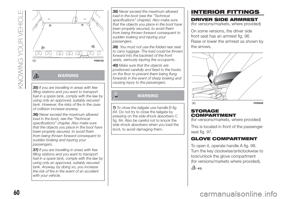
40)Make sure that the objects are
positioned carefully and fixed to the hooks
on the floor to prevent them being flung
forwards in the event of sharp braking and
causing injury to the passengers.
WARNING
7)To close the tailgate use handle B fig.
84. Do not try to close the tailgate by
pressing on the side shock absorbers C
fig. 84. Also be careful not to knock the
side shock absorbers when you load the
boot, to avoid damaging them.
INTERIOR FITTINGS
DRIVER SIDE ARMREST
(for versions/markets, where provided)
On some versions, the driver side
front seat has an armrest fig. 96.
Raise or lower the armrest as shown by
the arrows.
STORAGE
COMPARTMENT
(for versions/markets, where provided)
This is located in front of the passenger
seat fig. 97.
GLOVE COMPARTMENT
To open it, operate handle A fig. 98.
Turn the key clockwise/anticlockwise to
lock/unlock the glove compartment
(for versions/markets where provided).
41)
95F0V0122
96F0V0058
60
KNOWING YOUR VEHICLE
Page 76 of 300
press theMENUbutton briefly
to return to the menu screen or hold
the button down to return to the
standard screen without storing.
Setting a speed limit
(SPEEd)
This function is used to set a speed
limit (km/h or mph); the driver is alerted
when this limit is exceeded (see
“Warning lights and messages”).
To set the desired speed limit, proceed
as follows:
- press theMENU
button briefly:
the display will show the wording
(SPEED) and the unit (km/h) or (mph)
previously set;
- press the
orbutton to select
speed limit activation (On) or
deactivation (Off);
- if the function is on, press the
or
button to select the required speed
limit and then pressMENU
to
confirm;NOTE The speed may be set in the
range from 30 to 200 km/h, or from 20
to 125 mph according to the previously
chosen unit (see “Setting the unit of
measurement” below). The setting will
increase/decrease by five units each
time the
/button is pressed. Hold
down the
/button to automatically
increase/decrease the setting rapidly.
Complete the adjustment with single
presses of the button when you
approach the desired value.
- press theMENU
button briefly to
return to the menu screen or hold the
button down to return to the standard
screen without storing.
To cancel the setting, proceed as
follows:
- briefly the pressMENU
button;
(On) will flash on the display;
- press button
, (Off) will flash on the
display;
- press theMENU
button briefly to
return to the menu screen or hold the
button down to return to the standard
screen without storing.
On some versions/markets, a warning
set to a fixed speed of 120 km/h which
cannot be excluded or adjusted is
present.Setting the clock (Hour);
With this function, it is possible to set
the time.
To adjust, proceed as follows:
- briefly press theMENU
button;
the “hours” will flash on the display;
- press the
orbutton to adjust;
- briefly press theMENU
button;
the “minutes” will flash on the display;
- press the
orbutton to adjust;
- press theMENU
button briefly to
return to the menu screen or hold the
button down to return to the standard
screen without storing.
Setting the distance unit
(Unit)
This function is used to set the unit of
measurement.
To adjust, proceed as follows:
- press theMENU
button briefly:
the display will show the wording (Unit)
and the previously set unit (km) or (mi);
- press
orto select the required
unit.
- press theMENU
button briefly to
return to the menu screen or hold the
button down to return to the standard
screen without storing.
72
KNOWING THE INSTRUMENT PANEL