warning light FIAT DOBLO COMBI 2018 Owner handbook (in English)
[x] Cancel search | Manufacturer: FIAT, Model Year: 2018, Model line: DOBLO COMBI, Model: FIAT DOBLO COMBI 2018Pages: 272, PDF Size: 23.75 MB
Page 114 of 272
The cold tyre inflation pressure must
not exceed the maximum inflation
pressure value printed on the side of
the tyre.
NOTE
The TPMS does not replace the
normal tyre maintenance service and
does not indicate any fault in a tyre.
Therefore, the TPMS should not be
used as pressure switch while adjusting
the tyre inflation pressure.
Driving with insufficient tyre pressure
causes their overheating and can
result in tyre failure. The low inflation
pressure reduces fuel efficiency and
tyre tread life and may also affect
handling and braking performance of
the vehicle.
The TPMS does not replace the
correct tyre maintenance. It is up to the
driver to maintain the correct tyre
pressure level measuring it with
a suitable pressure switch. This is
necessary even if the decrease in the
inflation pressure value does not cause
the tyre pressure control warning light
to switch on.
The TPMS warns the driver of any
condition of insufficient tyre pressure. If
this drops below the insufficient
pressure limit for any reason including
low temperature and normal pressure
loss of the tyre.
The seasonal temperature changes
affect tyre pressure.
IMPORTANT Monitoring and
maintaining the correct pressure in all
four tyres are particularly important.
Tyre pressure monitoring system
low pressure warning
IMPORTANT In the case of deflation of
more than one tyre sequentially, without
switching off and on the engine, from
the second tyre involved the acoustic
signal is not activated, only the
dedicated signal is shown on the
display.
To prevent the signal from being stored
in the event of pressure loss of a
subsequent tyre (with deactivation of
the acoustic signal), the ignition key
must be turned to MAR and then to
STOP, each time pressure is restored.
TPMS operation faults
The system fault is indicated by the
warning light
which first flashes for
75 seconds and then stays on steadily.
WARNING
101)The TPMS is optimised for the original
tyres and wheels provided. TPMS
pressures and alerts have been defined
according to the size of the tyres mounted
on the vehicle. Using equipment with
different size, type or kind may cause
irregular system operation or sensor
damage. Non-original spare wheels can
damage the sensor. Do not use tyre
sealant or balancing weights if the vehicle
is equipped with TPMS as these may
damage the sensors.
102)If the system signals a pressure
decrease on a specific tyre, it is
recommended to check the pressure on all
four tyres.
103)The TPMS does not relieve the driver
from the obligation to check the tyre
pressure every month; it is not even to be
considered a replacing system for
maintenance or a safety system
104)Tyre pressure must be checked with
tyres cold. Should it become necessary for
whatever reason to check pressure with
warm tyres, do not reduce pressure even
though it is higher than the prescribed
value, but repeat the check when tyres are
cold.
105)The TPMS cannot indicate sudden
tyre pressure drops (for example when
a tyre bursts). In this case, stop the vehicle,
braking with caution and avoiding abrupt
steering.
112
STARTING AND DRIVING
Page 115 of 272
106)The system only warns that the tyre
pressure is low: it is not able to inflate
them.
107)Insufficient tyre inflation increases fuel
consumption, reduces the tread duration
and may affect the capacity to drive safely.
108)Always refit the valve stem cap after
inspecting or adjusting tyre pressure.
This prevents dampness or dirt from
entering the valve stem and thus
the pressure control sensor from being
damaged.
109)The tyre repair kit (Fix&Go) provided
with the vehicle (for versions/markets,
where provided) is compatible with the
TPMS sensors; using sealants not
equivalent with that in the original kit may
adversely affect its operation. If sealants
not equivalent with the original ones are
used, it is recommended to have the
TPMS sensor operation checked by a
qualified repair centre.SPEED BLOCK
(for versions/markets, where provided)
The vehicle is equipped with a speed
limitation function that can be set at the
user's request to one of four predefined
values: 90, 100, 110, 130 km/h.
To activate/deactivate this function,
contact a Fiat Dealership.
Following the operation, a sticker will be
applied to the windscreen showing the
top speed setting.
IMPORTANT The speedometer could
indicate a higher maximum speed than
the effective one, set by the Dealership,
in accordance with the regulations in
force.
CRUISE CONTROL
(for versions/markets, where provided)
IN BRIEF
This is an electronic driving aid that
allows you to drive at a speed of
above 30 km/h on long and straight
dry roads (e.g. motorways) with
few driving changes at a preset
speed without having to press the
accelerator pedal. It is therefore not
recommended to use this device
on extra-urban roads with traffic. Do
not use it in town.
Activating the device
When the device is activated, warning
light
comes on together with the
relevant message in the instrument
panel (for versions/markets where
provided).
The speed adjustment function cannot
be activated in 1st or reverse gear; it
is advisable to activate the function
in 4th or higher gears.
When travelling downhill with the device
activated, the vehicle speed may
exceed the memorised one.
110) 111)
113
Page 117 of 272
by pressing the accelerator pedal (in
this case the system is not actually
turned off but the acceleration request
takes priority; the cruise control remains
activated, without the need to the
press button B fig. 133 to restore the
previous conditions once the
acceleration is over).
The device is automatically switched off
in the following cases:
if the ABS or ESC systems intervene
with the vehicle speed below the
set limit
in the event of system failure.
WARNING
110)When travelling with the device active,
never move the gear lever to neutral.
111)In the event of device faults or failures,
turn the ring nut A to OFF and contact a
Fiat Dealership.
TRACTION PLUS
SYSTEM
(for versions/markets, where provided)
Traction Plus is a driving aid, useful
for setting off in poor grip conditions
(snow, ice, mud, etc.) which allows the
drive force to be distributed in the
best way over the front axle when one
wheel is slipping.
Traction Plus acts by braking the
wheels with poor grip (or those slipping
more than the others), thereby
transferring the drive force to those
which have greater grip on the ground.
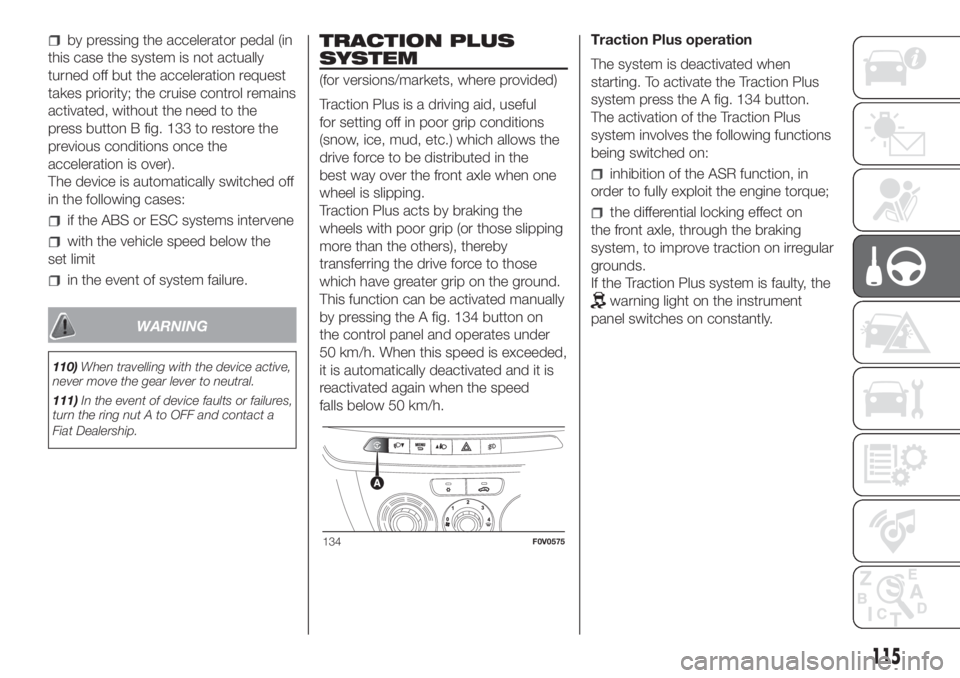
This function can be activated manually
by pressing the A fig. 134 button on
the control panel and operates under
50 km/h. When this speed is exceeded,
it is automatically deactivated and it is
reactivated again when the speed
falls below 50 km/h.Traction Plus operation
The system is deactivated when
starting. To activate the Traction Plus
system press the A fig. 134 button.
The activation of the Traction Plus
system involves the following functions
being switched on:
inhibition of the ASR function, in
order to fully exploit the engine torque;
the differential locking effect on
the front axle, through the braking
system, to improve traction on irregular
grounds.
If the Traction Plus system is faulty, the
warning light on the instrument
panel switches on constantly.
134F0V0575
115
Page 123 of 272
IN AN EMERGENCY
A punctured tyre or a burnt-out bulb?
At times, a problem may interfere
with our journey.
The pages on emergencies can help
you to deal with critical situations
independently and with calm.
In an emergency we recommend that
you call the freephone number found in
the Warranty Booklet.
It is also possible to call the 00 800
3428 0000 freephone number to
search the nearest Fiat Dealership.HAZARD WARNING LIGHTS...........122
REPLACING A BULB ......................122
REPLACING AN EXTERIOR BULB ..125
REPLACING INTERIOR BULBS ......128
REPLACING FUSES........................129
REPLACING A WHEEL ...................134
FIX&GO AUTOMATIC KIT ................138
EMERGENCY STARTING ................141
FUEL CUT-OFF SYSTEM ................142
LIFTING THE VEHICLE....................142
TOWING THE VEHICLE ..................143
121
Page 124 of 272
HAZARD WARNING
LIGHTS
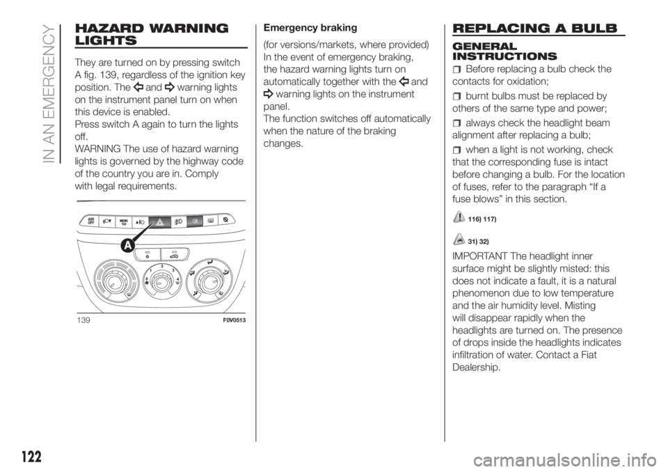
They are turned on by pressing switch
A fig. 139, regardless of the ignition key
position. The
andwarning lights
on the instrument panel turn on when
this device is enabled.
Press switch A again to turn the lights
off.
WARNING The use of hazard warning
lights is governed by the highway code
of the country you are in. Comply
with legal requirements.Emergency braking
(for versions/markets, where provided)
In the event of emergency braking,
the hazard warning lights turn on
automatically together with theand
warning lights on the instrument
panel.
The function switches off automatically
when the nature of the braking
changes.
REPLACING A BULB
GENERAL
INSTRUCTIONS
Before replacing a bulb check the
contacts for oxidation;
burnt bulbs must be replaced by
others of the same type and power;
always check the headlight beam
alignment after replacing a bulb;
when a light is not working, check
that the corresponding fuse is intact
before changing a bulb. For the location
of fuses, refer to the paragraph “If a
fuse blows” in this section.
116) 117)
31) 32)
IMPORTANT The headlight inner
surface might be slightly misted: this
does not indicate a fault, it is a natural
phenomenon due to low temperature
and the air humidity level. Misting
will disappear rapidly when the
headlights are turned on. The presence
of drops inside the headlights indicates
infiltration of water. Contact a Fiat
Dealership.
139F0V0513
122
IN AN EMERGENCY
Page 125 of 272
TYPES OF BULBS
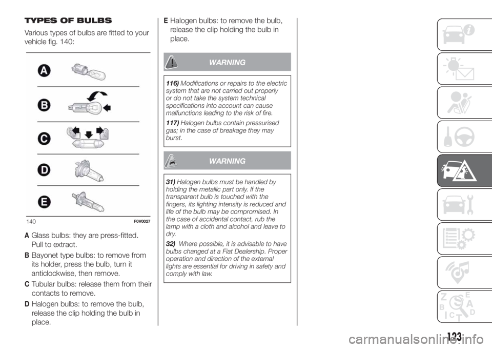
Various types of bulbs are fitted to your
vehicle fig. 140:
AGlass bulbs: they are press-fitted.
Pull to extract.
BBayonet type bulbs: to remove from
its holder, press the bulb, turn it
anticlockwise, then remove.
CTubular bulbs: release them from their
contacts to remove.
DHalogen bulbs: to remove the bulb,
release the clip holding the bulb in
place.
EHalogen bulbs: to remove the bulb,
release the clip holding the bulb in
place.
WARNING
116)Modifications or repairs to the electric
system that are not carried out properly
or do not take the system technical
specifications into account can cause
malfunctions leading to the risk of fire.
117)Halogen bulbs contain pressurised
gas; in the case of breakage they may
burst.
WARNING
31)Halogen bulbs must be handled by
holding the metallic part only. If the
transparent bulb is touched with the
fingers, its lighting intensity is reduced and
life of the bulb may be compromised. In
the case of accidental contact, rub the
lamp with a cloth and alcohol and leave to
dry.
32)Where possible, it is advisable to have
bulbs changed at a Fiat Dealership. Proper
operation and direction of the external
lights are essential for driving in safety and
comply with law.
140F0V0027
123
Page 134 of 272
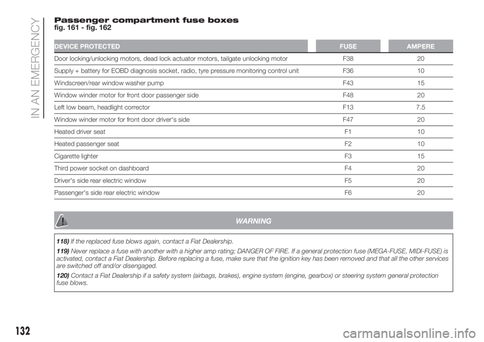
Passenger compartment fuse boxes
fig. 161 - fig. 162
DEVICE PROTECTEDFUSE AMPERE
Door locking/unlocking motors, dead lock actuator motors, tailgate unlocking motor F38 20
Supply + battery for EOBD diagnosis socket, radio, tyre pressure monitoring control unit F36 10
Windscreen/rear window washer pump F43 15
Window winder motor for front door passenger side F48 20
Left low beam, headlight corrector F13 7.5
Window winder motor for front door driver's side F47 20
Heated driver seatF1 10
Heated passenger seatF2 10
Cigarette lighterF3 15
Third power socket on dashboard F4 20
Driver's side rear electric window F5 20
Passenger's side rear electric window F6 20
WARNING
118)If the replaced fuse blows again, contact a Fiat Dealership.
119)Never replace a fuse with another with a higher amp rating; DANGER OF FIRE. If a general protection fuse (MEGA-FUSE, MIDI-FUSE) is
activated, contact a Fiat Dealership. Before replacing a fuse, make sure that the ignition key has been removed and that all the other services
are switched off and/or disengaged.
120)Contact a Fiat Dealership if a safety system (airbags, brakes), engine system (engine, gearbox) or steering system general protection
fuse blows.
132
IN AN EMERGENCY
Page 136 of 272
REPLACING A
WHEEL
The vehicle is originally equipped with
the Fix&Go automatic quick tyre repair
kit (see instructions in the next section).
As an alternative, the vehicle may
have a normal-sized spare wheel.
Wheel changing and correct use of the
jack and spare wheel call for some
precautions, as listed below.
121) 122) 123) 124)
Note for one-way tyres
One-way tyres have a few arrows on
the side indicating the rotation direction.
If a wheel is changed (when punctured,
for example) the direction of the arrows
on the spare wheel tyre may not
coincide with the rotation direction of
the wheel to be replaced.
In these conditions, too, the tyre still
maintains its safety features.
Anyway, it is recommended to have the
wheel repaired and refitted as soon as
possible, as the best performance is
achieved when the rotation direction of
all tyres coincides with the one
indicated by the arrows.JACK
Please note that:
the jack weight is 4 kg;
the jack requires no adjustment;
the jack cannot be repaired and in
the event of a fault it must be replaced
by another genuine one;
no tool other than its cranking
device may be fitted on the jack.
WHEEL REPLACEMENT
PROCEDURE
To change a wheel, proceed as follows:
stop the vehicle in a position that is
not dangerous for oncoming traffic
where you can change the wheel safely.
The ground must be flat and sufficiently
compact;
switch off the engine and pull the
handbrake;
engage first gear or reverse;
wear the reflective safety jacket
(compulsory by law in certain countries)
before getting out of the vehicle;
indicate that the vehicle has broken
down using the devices required by
the law in the current country (e.g.
warning triangle, hazard lights, etc.);
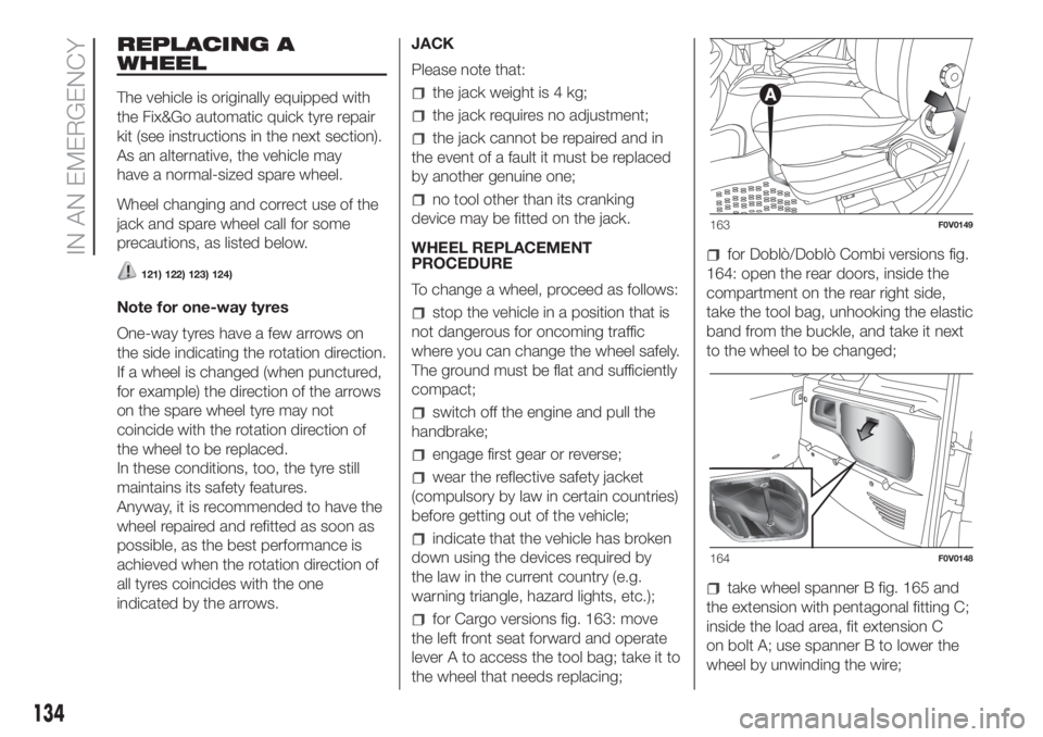
for Cargo versions fig. 163: move
the left front seat forward and operate
lever A to access the tool bag; take it to
the wheel that needs replacing;
for Doblò/Doblò Combi versions fig.
164: open the rear doors, inside the
compartment on the rear right side,
take the tool bag, unhooking the elastic
band from the buckle, and take it next
to the wheel to be changed;
take wheel spanner B fig. 165 and
the extension with pentagonal fitting C;
inside the load area, fit extension C
on bolt A; use spanner B to lower the
wheel by unwinding the wire;
163F0V0149
164F0V0148
134
IN AN EMERGENCY
Page 140 of 272
check that the position of the
replaced wheel under the platform is
correct (the lifting system is equipped
with a clutch to limit the end of the
stroke, incorrect positioning may
jeopardise safety;)
put the jack and the tools back in
the dedicated tool bag;
reposition the tool bag behind the
left side seat (Cargo versions) or, resting
the bottom of the bag against the side
panel, in the compartment inside the
rear right side (Doblò/Doblò Combi
versions).
WARNING
121)The spare wheel (where provided) is
specifically for your vehicle. Therefore, it
must not be used on other models. Do not
use spare wheels of other models on
your vehicle. The spare wheel must be
used only in an emergency. Use of the
spare wheel must kept to the minimum
necessary.122)Use your hazard lights, warning
triangle, etc to show that your vehicle is
stationary. Passengers should get out
of the vehicle, particularly if it is heavily
loaded, and wait for the wheel to be
changed away from the traffic. If you are on
a slope or uneven surface, place wedges
or other suitable objects under the wheels
to secure the vehicle. Have the wheel
repaired and refitted as soon as possible.
Do not apply grease to the bolt threads
before fitting: they could come unscrewed.
123)Use the jack only to replace wheels
on the vehicle with which it is supplied
or on other vehicles of the same model.
Never use the jack for other purposes,
such as lifting other models. Never use the
jack to carry out repairs under the vehicle.
Incorrect positioning of the jack may cause
the lifted vehicle to fall. Do not use the
jack for loads higher than the one shown
on its label.
124)Incorrect hub cap assembly may
cause it to come off when the vehicle is
moving. Never tamper with the inflation
valve. Never introduce tools of any kind
between rim and tyre. Check tyre and
space-saver wheel pressures regularly,
complying with the values given in the
"Technical specifications" chapter.
FIX&GO AUTOMATIC
KIT
125) 126)
37)
DESCRIPTION
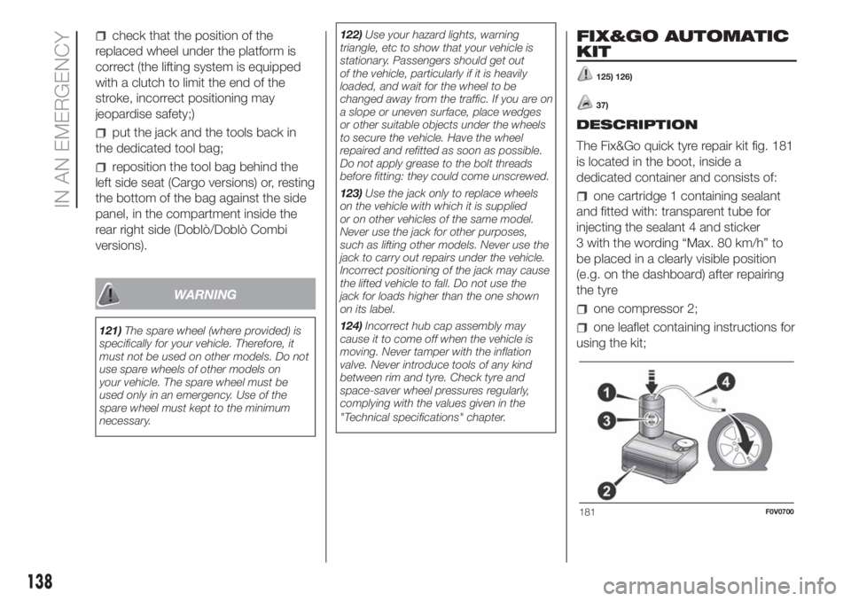
The Fix&Go quick tyre repair kit fig. 181
is located in the boot, inside a
dedicated container and consists of:
one cartridge 1 containing sealant
and fitted with: transparent tube for
injecting the sealant 4 and sticker
3 with the wording “Max. 80 km/h” to
be placed in a clearly visible position
(e.g. on the dashboard) after repairing
the tyre
one compressor 2;
one leaflet containing instructions for
using the kit;
181F0V0700
138
IN AN EMERGENCY
Page 141 of 272
TYRE REPAIRING AND
PRESSURE RESTORING
PROCEDURE
Proceed as follows:
stop the car in a position that is not
dangerous for oncoming traffic where
you can carry out the procedure safely.
The ground must be flat and sufficiently
compact;
stop the engine, engage the hazard
warning lights and the parking brake;
wear the reflective safety jacket
before getting out of the car (anyway
comply with the laws in force in the
country you are driving in);
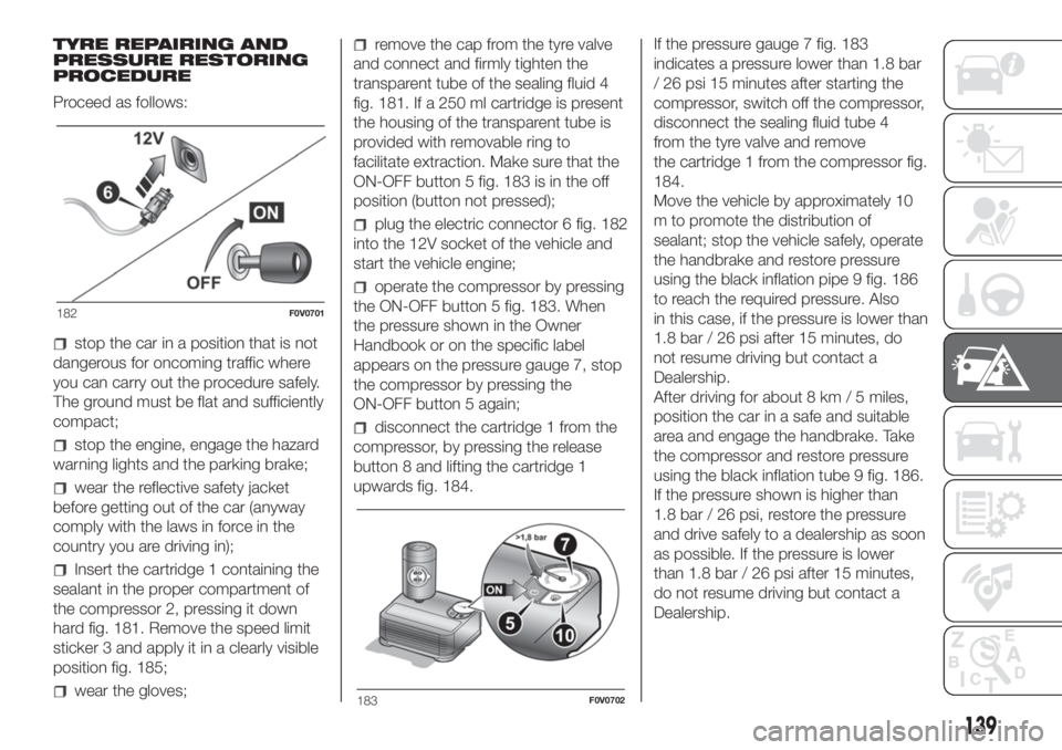
Insert the cartridge 1 containing the
sealant in the proper compartment of
the compressor 2, pressing it down
hard fig. 181. Remove the speed limit
sticker 3 and apply it in a clearly visible
position fig. 185;
wear the gloves;
remove the cap from the tyre valve
and connect and firmly tighten the
transparent tube of the sealing fluid 4
fig. 181. If a 250 ml cartridge is present
the housing of the transparent tube is
provided with removable ring to
facilitate extraction. Make sure that the
ON-OFF button 5 fig. 183 is in the off
position (button not pressed);
plug the electric connector 6 fig. 182
into the 12V socket of the vehicle and
start the vehicle engine;
operate the compressor by pressing
the ON-OFF button 5 fig. 183. When
the pressure shown in the Owner
Handbook or on the specific label
appears on the pressure gauge 7, stop
the compressor by pressing the
ON-OFF button 5 again;
disconnect the cartridge 1 from the
compressor, by pressing the release
button 8 and lifting the cartridge 1
upwards fig. 184.If the pressure gauge 7 fig. 183
indicates a pressure lower than 1.8 bar
/ 26 psi 15 minutes after starting the
compressor, switch off the compressor,
disconnect the sealing fluid tube 4
from the tyre valve and remove
the cartridge 1 from the compressor fig.
184.
Move the vehicle by approximately 10
m to promote the distribution of
sealant; stop the vehicle safely, operate
the handbrake and restore pressure
using the black inflation pipe 9 fig. 186
to reach the required pressure. Also
in this case, if the pressure is lower than
1.8 bar / 26 psi after 15 minutes, do
not resume driving but contact a
Dealership.
After driving for about 8 km / 5 miles,
position the car in a safe and suitable
area and engage the handbrake. Take
the compressor and restore pressure
using the black inflation tube 9 fig. 186.
If the pressure shown is higher than
1.8 bar / 26 psi, restore the pressure
and drive safely to a dealership as soon
as possible. If the pressure is lower
than 1.8 bar / 26 psi after 15 minutes,
do not resume driving but contact a
Dealership.
182F0V0701
183F0V0702
139