ESP FIAT DUCATO 2007 Owner handbook (in English)
[x] Cancel search | Manufacturer: FIAT, Model Year: 2007, Model line: DUCATO, Model: FIAT DUCATO 2007Pages: 282, PDF Size: 4.49 MB
Page 63 of 282
62
SAFETY
DEVICES
CORRECT USE
OF THE
VEHICLE
WARNING
LIGHTS AND
MESSAGES
IN AN
EMERGENCY
VEHICLE
MAINTENANCE
TECHNICAL
SPECIFICATIONS
INDEX
DASHBOARD
AND CONTROLS
It is however inadvisable to use it on
rainy/cold days as it would considerably
increase the possibility of the windows
misting inside, especially if the climate con-
trol system is off.
With low outdoor temperatures, recir-
culation is turned off (with air intake from
outside) to prevent possible misting.
It is inadvisable to use the inside air re-
circulation function with low outside tem-
perature as windows may mist over quick-
ly.Climate control
compressor on/off
button (F)
Press pushbutton √to
turn off the climate control system
compressor if it was on previously and
the logo on the display is turned off.
When the pushbutton is pressed with
the led off, control of compressor
activation is restored to automatic
control by the system. This condition is
indicated by the logo lighting up on the
display.
When turning the compressor off, the sys-
tem will deactivate air recirculation to pre-
vent window misting up. Although the sys-
tem is able to keep the required tempera-
ture, the wording FULL will disappear from
the display. If the system is no longer able
to keep the required temperature, tem-
perature figures will flash and the wording
AUTO will disappear from the display.IMPORTANT With the climate control
compressor off, it is not possible to admit
air to the passenger compartment with a
temperature below the outside tempera-
ture; moreover, under certain environ-
mental conditions, windows could mist up
fastly since air is not dehumidified.
The switching off of the climate control
compressor remains in storage even when
the engine has been stopped.
To restore automatic control for switch-
ing on the climate control compressor,
press again button √(in this event the sys-
tem will just work as heater) or press but-
ton AUTO.
Page 70 of 282
69
SAFETY
DEVICES
CORRECT USE
OF THE
VEHICLE
WARNING
LIGHTS AND
MESSAGES
IN AN
EMERGENCY
VEHICLE
MAINTENANCE
TECHNICAL
SPECIFICATIONS
INDEX
DASHBOARD
AND CONTROLS
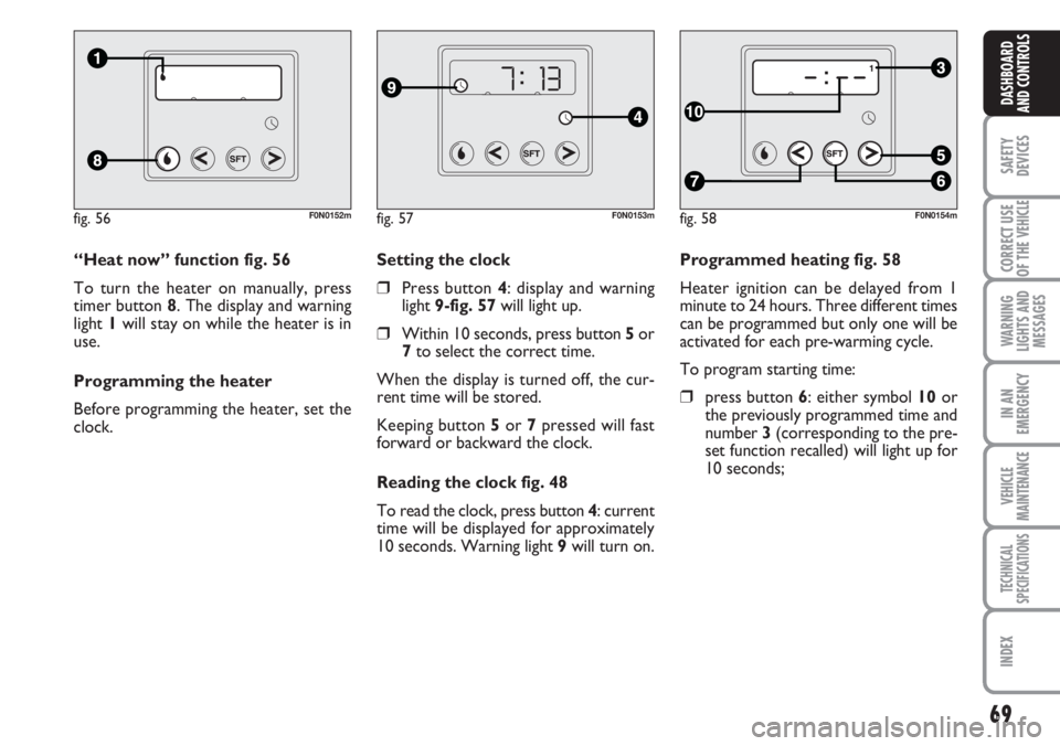
Programmed heating fig. 58
Heater ignition can be delayed from 1
minute to 24 hours. Three different times
can be programmed but only one will be
activated for each pre-warming cycle.
To program starting time:
❒press button 6: either symbol 10 or
the previously programmed time and
number 3 (corresponding to the pre-
set function recalled) will light up for
10 seconds; Setting the clock
❒Press button 4: display and warning
light 9-fig. 57will light up.
❒Within 10 seconds, press button 5or
7to select the correct time.
When the display is turned off, the cur-
rent time will be stored.
Keeping button 5or 7pressed will fast
forward or backward the clock.
Reading the clock fig. 48
To read the clock, press button 4: current
time will be displayed for approximately
10 seconds. Warning light 9will turn on. “Heat now” function fig. 56
To turn the heater on manually, press
timer button 8. The display and warning
light 1will stay on while the heater is in
use.
Programming the heater
Before programming the heater, set the
clock.
fig. 56F0N0152mfig. 57F0N0153mfig. 58F0N0154m
Page 71 of 282
70
SAFETY
DEVICES
CORRECT USE
OF THE
VEHICLE
WARNING
LIGHTS AND
MESSAGES
IN AN
EMERGENCY
VEHICLE
MAINTENANCE
TECHNICAL
SPECIFICATIONS
INDEX
DASHBOARD
AND CONTROLS
IMPORTANT To recall other preset
times, press button 6within 10 seconds.
– press button 5or 7within 10 seconds
to select the starting time required.
IMPORTANT Time is stored when:
❒starting time goes off;
❒number 3 is displayed;
❒the display turns on.
IMPORTANT At turning on:
❒warning light corresponding to flame
1 on the display will turn on;
❒number 3 will turn off.
Deleting a programmed
starting time fig. 58
To delete the programmed starting time,
press button 6briefly: the display light will
go off and number 3corresponding to the
selected preset time will disappear.Recalling a pre-set time fig. 59
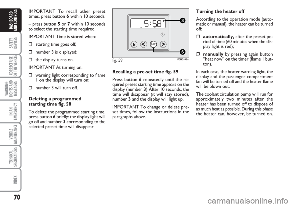
Press button 6repeatedly until the re-
quired preset starting time appears on the
display (number 3) After 10 seconds, the
time will disappear (it will stay stored),
number 3 and the display will light up.
IMPORTANT To change or delete pre-
set times, follow the instructions in the
paragraphs above.Turning the heater off
According to the operation mode (auto-
matic or manual), the heater can be turned
off:
❒automatically,after the preset pe-
riod of time (60 minutes when the dis-
play light is red);
❒manuallyby pressing again button
“heat now” on the timer (flame 1 but-
ton).
In each case, the heater warning light, the
display and the passenger compartment
fan will be turned off and the heater flame
will be blown out.
The coolant circulation pump will run for
approximately two minutes after the
heater has been turned off to dispose of
as much heat as possible. During this phase
the heater can, however, be turned on.
fig. 59F0N0155m
Page 81 of 282
80
SAFETY
DEVICES
CORRECT USE
OF THE
VEHICLE
WARNING
LIGHTS AND
MESSAGES
IN AN
EMERGENCY
VEHICLE
MAINTENANCE
TECHNICAL
SPECIFICATIONS
INDEX
DASHBOARD
AND CONTROLS
TO INCREASE THE MEMORISED
SPEED
The speed memorised can be increased in
two ways:
❒pressing the accelerator and then
memorising the new speed reached;
or
❒moving the stalk upwards (+).
Each operation of the stalk will corre-
spond to a slight increase in speed (about
1 km/h), while keeping the stalk upwards
will correspond to a continuous speed in-
crease.
TO REDUCE MEMORISED
SPEED
The speed memorised can be increased in
two ways:
❒disengaging the device and then mem-
orising the new speed;
or
❒moving the stalk downwards (–) until
reaching the new speed which will be
memorised automatically.
Each operation of the stalk will corre-
spond to a slight reduction in speed (about
1 km/h), while keeping the stalk down-
wards will correspond to a continuous
speed reduction.DEVICE DISENGAGEMENT
The device can be disengaged in the fol-
lowing ways:
❒turning the knurled ring Ato OFF;
❒turning the engine off;
❒pressing the brake pedal or engaging
the hand brake;
❒pressing the clutch pedal;
❒shifting gear with automatic transmis-
sion in sequential mode;
❒with vehicle speed below the preset
limit;
❒pressing the accelerator pedal; in this
case the system is not really disen-
gaged but the request for acceleration
takes priority over the system. The
cruise control is however active and it
will not be necessary to press button
RES to resume previous conditions
after ending acceleration.The device is automatically deactivated in
one of the following cases:
❒ABS or ESP system cut-in;
❒system failure.
When travelling with the de-
vice on, never set the
gearshift lever to neutral.
In the event of device mal-
function or failure, turn the
knurled ring A to OFF and contact a
Fiat Dealership after checking the
protection fuse integrity.
WARNING
WARNING
Page 92 of 282
91
SAFETY
DEVICES
CORRECT USE
OF THE
VEHICLE
WARNING
LIGHTS AND
MESSAGES
IN AN
EMERGENCY
VEHICLE
MAINTENANCE
TECHNICAL
SPECIFICATIONS
INDEX
DASHBOARD
AND CONTROLS
MULTIMETER
See the booklet provided by the multi-
meter Manufacturer for more detailed in-
formation on operation and use.
Multimeter installation is compulsory if the
vehicle weight (with or without the trail-
er) exceeds 3.5 tons.
IMPORTANT Changes to the instrument
or to the signal transmission system which
effects the instrument recordings, espe-
cially for fraudulent purposes, may be a
criminal offence.
IMPORTANT For all versions fitted with
tachograph (excluding the Minibus ver-
sion), it is suggested to remove the 10 A
red fuse marked with F39 (control unit) in
case of prolonged vehicle stop (over 10
days).
IMPORTANT When a macrograph is fit-
ted and the vehicle has been parked for
longer than 5 days, it is advisable to dis-
connect the battery negative terminal to
preserve the charge status. USER INTERFACE
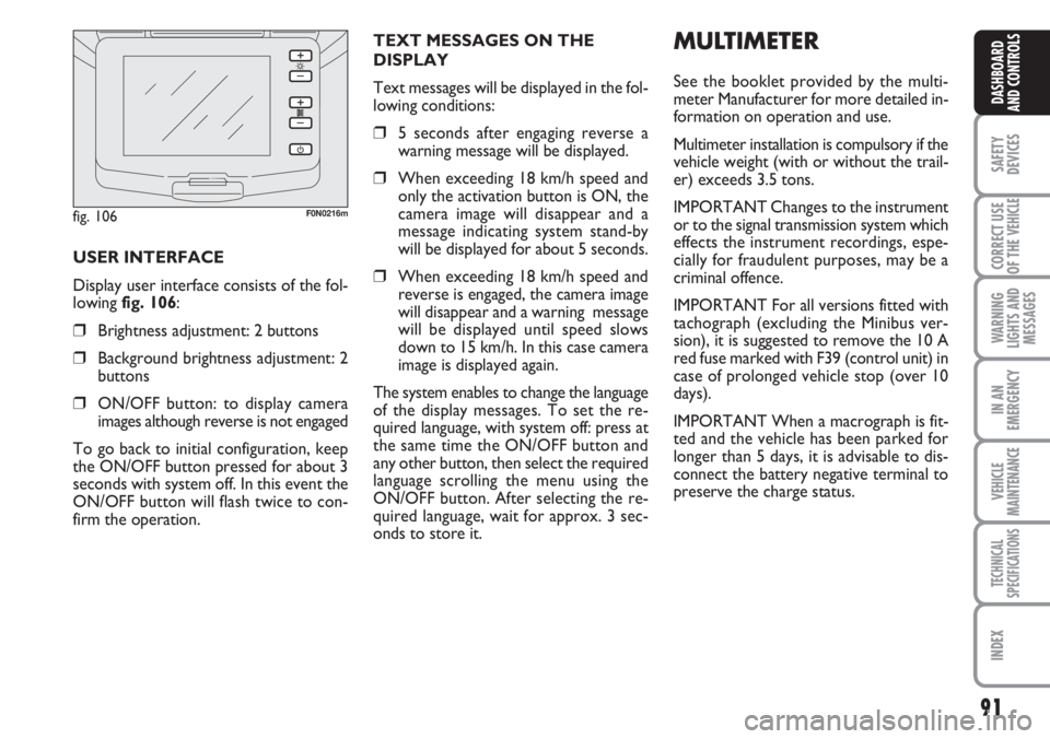
Display user interface consists of the fol-
lowing fig. 106:
❒Brightness adjustment: 2 buttons
❒Background brightness adjustment: 2
buttons
❒ON/OFF button: to display camera
images although reverse is not engaged
To go back to initial configuration, keep
the ON/OFF button pressed for about 3
seconds with system off. In this event the
ON/OFF button will flash twice to con-
firm the operation.TEXT MESSAGES ON THE
DISPLAY
Text messages will be displayed in the fol-
lowing conditions:
❒5 seconds after engaging reverse a
warning message will be displayed.
❒When exceeding 18 km/h speed and
only the activation button is ON, the
camera image will disappear and a
message indicating system stand-by
will be displayed for about 5 seconds.
❒When exceeding 18 km/h speed and
reverse is engaged, the camera image
will disappear and a warning message
will be displayed until speed slows
down to 15 km/h. In this case camera
image is displayed again.
The system enables to change the language
of the display messages. To set the re-
quired language, with system off: press at
the same time the ON/OFF button and
any other button, then select the required
language scrolling the menu using the
ON/OFF button. After selecting the re-
quired language, wait for approx. 3 sec-
onds to store it.
fig. 106F0N0216m
Page 93 of 282
92
SAFETY
DEVICES
CORRECT USE
OF THE
VEHICLE
WARNING
LIGHTS AND
MESSAGES
IN AN
EMERGENCY
VEHICLE
MAINTENANCE
TECHNICAL
SPECIFICATIONS
INDEX
DASHBOARD
AND CONTROLS
IMPORTANT
Do not use abrasive detergents or sol-
vents to clean the device. To clean its ex-
ternal surface, use a wet cloth or special
products for cleaning synthetic materials.
The multimeter is installed and sealed with
lead by authorised personnel: access to
the device and relevant power and record-
ing cables is forbidden.
The vehicle owner is responsible for gov-
erning the instrument use. The inspection
must be carried out at least every two
years and will include a test to confirm
correct operation.
After the inspection, check that the plate
is updated with specified data.DOORS
CENTRAL DOOR
LOCKING/UNLOCKING SYSTEM
Locking from the outside
With the doors closed, press the button
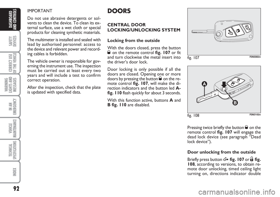
Øon the remote control fig. 107or fit
and turn clockwise the metal insert into
the driver’s door lock.
Door locking is only possible if all the
doors are closed. Opening one or more
doors by pressing the button
Øon the re-
mote control fig. 107, will make the di-
rection indicators and the button led A-
fig. 110flash quickly for about 3 seconds.
With this function active, buttons Aand
B fig. 110are disabled.
fig. 107F0N0060m
Pressing twice briefly the button Øon the
remote control fig. 107will engage the
dead lock device (see paragraph “Dead
lock device”).
Door unlocking from the outside
Briefly press button
Æfig. 107or Ëfig.
108, according to versions, to obtain re-
mote door unlocking, timed ceiling light
turning on, directions indicator double
fig. 108F0N0145m
Page 96 of 282
95
SAFETY
DEVICES
CORRECT USE
OF THE
VEHICLE
WARNING
LIGHTS AND
MESSAGES
IN AN
EMERGENCY
VEHICLE
MAINTENANCE
TECHNICAL
SPECIFICATIONS
INDEX
DASHBOARD
AND CONTROLS
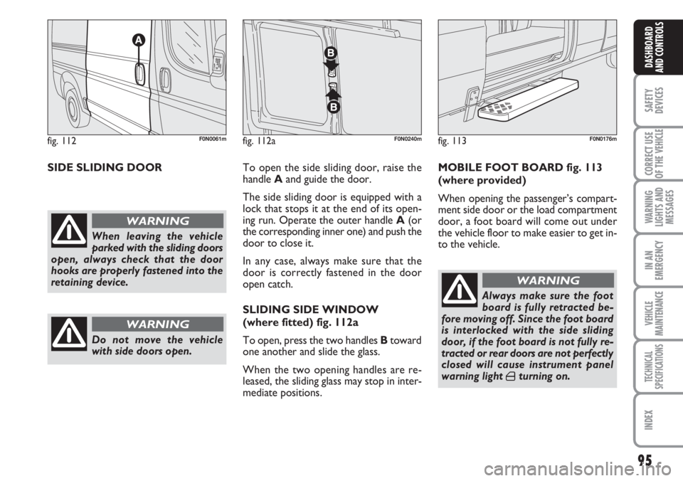
SIDE SLIDING DOORTo open the side sliding door, raise the
handle Aand guide the door.
The side sliding door is equipped with a
lock that stops it at the end of its open-
ing run. Operate the outer handle A(or
the corresponding inner one) and push the
door to close it.
In any case, always make sure that the
door is correctly fastened in the door
open catch.
SLIDING SIDE WINDOW
(where fitted) fig. 112a
To open, press the two handles Btoward
one another and slide the glass.
When the two opening handles are re-
leased, the sliding glass may stop in inter-
mediate positions.MOBILE FOOT BOARD fig. 113
(where provided)
When opening the passenger’s compart-
ment side door or the load compartment
door, a foot board will come out under
the vehicle floor to make easier to get in-
to the vehicle.
fig. 112F0N0061m
When leaving the vehicle
parked with the sliding doors
open, always check that the door
hooks are properly fastened into the
retaining device.
WARNING
Do not move the vehicle
with side doors open.
WARNING
Always make sure the foot
board is fully retracted be-
fore moving off. Since the foot board
is interlocked with the side sliding
door, if the foot board is not fully re-
tracted or rear doors are not perfectly
closed will cause instrument panel
warning light
´turning on.
WARNING
fig. 113F0N0176mfig. 112aF0N0240m
Page 104 of 282
103
SAFETY
DEVICES
CORRECT USE
OF THE
VEHICLE
WARNING
LIGHTS AND
MESSAGES
IN AN
EMERGENCY
VEHICLE
MAINTENANCE
TECHNICAL
SPECIFICATIONS
INDEX
DASHBOARD
AND CONTROLS
BRAKE ASSIST
(emergency braking assistance
integral with ESP) (where provided)
The system, which cannot be cut out, rec-
ognizes emergency braking (on the ground
of the brake pedal operation speed) and
considerably increases the pressure in the
brake circuit.
Brake Assist is deactivated on the versions
equipped with ESP, in the event of ESP sys-
tem failure (indicated by warning light
áswitching on together with the message
on the multifunction display, where pro-
vided).
ESP SYSTEM
(Electronic Stability
Program)
(where provided)
The ESP system is an electronic system
controlling the vehicle stability in the event
of tyre grip loss.
The ESP system is therefore particularly
useful when grip conditions of the road sur-
faces changes.
In addition to the ESP system, ASR system
and Hill Holder, (where provided) also the
MSR system (adjusting the engine braking
torque) and the HBA system (improving
the braking force during emergency brak-
ing) are provided.
ESP SYSTEM INTERVENTION
It is signalled by the blinking of the warn-
ing light áon the instrument panel, to in-
form the driver that the vehicle is in crit-
ical stability and grip conditions.
When the ABS cuts in, and
you feel the brake pedal pul-
sating, do not remove your foot, but
keep it pressed; in doing so you will
stop in the shortest amount of space
possible under the current road con-
ditions.
WARNING
EBD failure
EBD failure is indicated by the turning on
of warning lights
>and xon the in-
strument panel together with the dedi-
cated message on the multifunction dis-
play (where provided), (see section
“Warning lights and messages”).
In this case with sharp braking the rear
wheels might lock too early, with the pos-
sibility of skidding. Drive extremely care-
fully to the nearest Fiat Dealership to have
the system checked.
If warning light xalone
comes on (together with the
message on the multifunction display,
where provided), stop the vehicle im-
mediately and contact the nearest Fi-
at Dealership. Fluid leaks from the hy-
draulic system, in fact, can compro-
mise the braking system, both tradi-
tional systems and systems with ABS.
WARNING
Page 105 of 282
104
SAFETY
DEVICES
CORRECT USE
OF THE
VEHICLE
WARNING
LIGHTS AND
MESSAGES
IN AN
EMERGENCY
VEHICLE
MAINTENANCE
TECHNICAL
SPECIFICATIONS
INDEX
DASHBOARD
AND CONTROLS
ESP SYSTEM ACTIVATION
The ESP system is automatically activat-
ed when the vehicle is started and cannot
be de-activated.
FAILURE INDICATIONS
In the event of failure, the ESP system is
automatically disconnected, the warning
light
á, comes on with fixed light on the
instrument panel, together with the mes-
sage on the multifunction display (where
provided) (see section “Warning lights and
messages”) and with the button led ASR.
In this case contact a Fiat Dealership as
soon as possible.
Performance of the ESP sys-
tem, in terms of active safe-
ty should not induce the driver to take
pointless and unnecessary risks. The
style of driving must in any case al-
ways be adapted to the conditions of
the road surface, visibility and traffic.
Road safety is always the driver’s re-
sponsibility.
WARNING
HILL HOLDER SYSTEM
This system is an integral part of the ESP
system and it is provided to facilitate start-
ing on slopes.
It will activate automatically with the fol-
lowing conditions:
❒uphill: vehicle at a standstill on a road
with a gradient higher than 5%, engine
running, clutch and brake pedal
pressed, gearbox to neutral or en-
gaged gear other than reverse.
❒downhill: vehicle at a standstill on a
road with a gradient higher than 5%,
engine running, clutch and brake ped-
al pressed and reverse gear engaged.
At pickup the ESP system control unit will
keep brake force on wheels until reaching
the torque suitable for starting, or in any
case for max. 2 seconds in order to pass
easily from the brake pedal to the accel-
erator pedal.
After two seconds without starting, the
system will deactivate automatically by re-
leasing gradually the brake force.
At releasing, the typical brake disengage-
ment noise indicating that the vehicle is
going to move will be heard.Failure indications
System failure is indicated by the turning
on of warning light
á(see section “Warn-
ing lights and messages”).
IMPORTANT The Hill Holder system is
not a parking brake therefore, never leave
the vehicle without having engaged the
handbrake, turned the engine off and en-
gaged the first speed.
For correct operation of the
ESP and ASR systems, the
tyres must absolutely be of the same
brand and type on all wheels, in per-
fect conditions and, above all, of
type, brand and size specified.
WARNING
Page 106 of 282
105
SAFETY
DEVICES
CORRECT USE
OF THE
VEHICLE
WARNING
LIGHTS AND
MESSAGES
IN AN
EMERGENCY
VEHICLE
MAINTENANCE
TECHNICAL
SPECIFICATIONS
INDEX
DASHBOARD
AND CONTROLS
MSR system
(engine braking torque control)
It is an integral part of the ASR system that
in case of sudden gear shifting, cuts in pro-
viding torque to the engine thus prevent-
ing excessive driving wheel drive that, spe-
cially in poor grip conditions, can lead to
loss of stability.
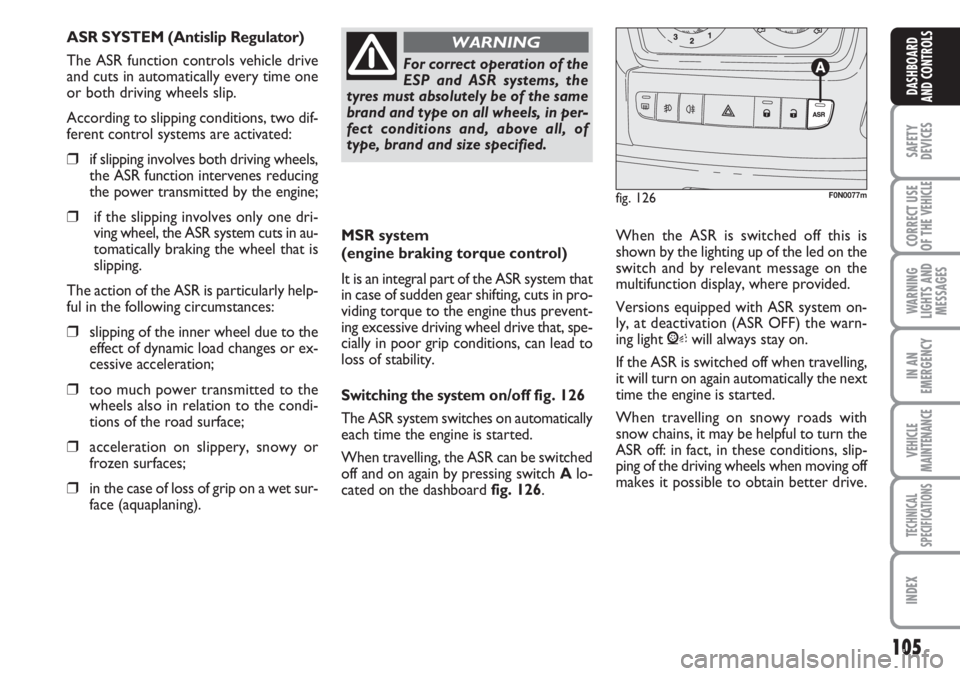
Switching the systemon/off fig. 126
The ASR system switches on automatically
each time the engine is started.
When travelling, the ASR can be switched
off and on again by pressing switch Alo-
cated on the dashboard fig. 126. When the ASR is switched off this is
shown by the lighting up of the led on the
switch and by relevant message on the
multifunction display, where provided.
Versions equipped with ASR system on-
ly, at deactivation (ASR OFF) the warn-
ing light Vwill always stay on.
If the ASR is switched off when travelling,
it will turn on again automatically the next
time the engine is started.
When travelling on snowy roads with
snow chains, it may be helpful to turn the
ASR off: in fact, in these conditions, slip-
ping of the driving wheels when moving off
makes it possible to obtain better drive.
For correct operation of the
ESP and ASR systems, the
tyres must absolutely be of the same
brand and type on all wheels, in per-
fect conditions and, above all, of
type, brand and size specified.
WARNING
fig. 126F0N0077m
ASR SYSTEM (Antislip Regulator)
The ASR function controls vehicle drive
and cuts in automatically every time one
or both driving wheels slip.
According to slipping conditions, two dif-
ferent control systems are activated:
❒if slipping involves both driving wheels,
the ASR function intervenes reducing
the power transmitted by the engine;
❒if the slipping involves only one dri-
ving wheel, the ASR system cuts in au-
tomatically braking the wheel that is
slipping.
The action of the ASR is particularly help-
ful in the following circumstances:
❒slipping of the inner wheel due to the
effect of dynamic load changes or ex-
cessive acceleration;
❒too much power transmitted to the
wheels also in relation to the condi-
tions of the road surface;
❒acceleration on slippery, snowy or
frozen surfaces;
❒in the case of loss of grip on a wet sur-
face (aquaplaning).