key FIAT DUCATO 2007 Owner handbook (in English)
[x] Cancel search | Manufacturer: FIAT, Model Year: 2007, Model line: DUCATO, Model: FIAT DUCATO 2007Pages: 282, PDF Size: 4.49 MB
Page 16 of 282
15
SAFETY
DEVICES
CORRECT USE
OF THE
VEHICLE
WARNING
LIGHTS AND
MESSAGES
IN AN
EMERGENCY
VEHICLE
MAINTENANCE
TECHNICAL
SPECIFICATIONS
INDEX
DASHBOARD
AND CONTROLS
IGNITION
DEVICE
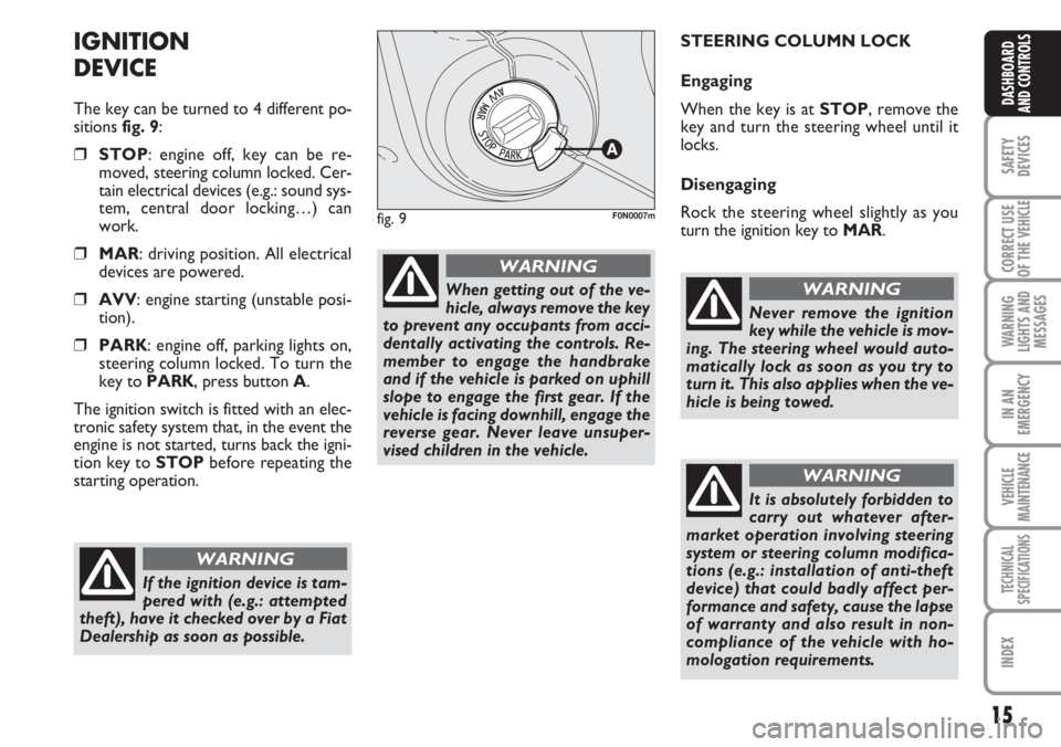
The key can be turned to 4 different po-
sitions fig. 9:
❒STOP: engine off, key can be re-
moved, steering column locked. Cer-
tain electrical devices (e.g.: sound sys-
tem, central door locking…) can
work.
❒MAR: driving position. All electrical
devices are powered.
❒AVV: engine starting (unstable posi-
tion).
❒PARK: engine off, parking lights on,
steering column locked. To turn the
key to PARK, press button A.
The ignition switch is fitted with an elec-
tronic safety system that, in the event the
engine is not started, turns back the igni-
tion key to STOPbefore repeating the
starting operation.STEERING COLUMN LOCK
Engaging
When the key is at STOP, remove the
key and turn the steering wheel until it
locks.
Disengaging
Rock the steering wheel slightly as you
turn the ignition key to MAR.
If the ignition device is tam-
pered with (e.g.: attempted
theft), have it checked over by a Fiat
Dealership as soon as possible.
WARNING
When getting out of the ve-
hicle, always remove the key
to prevent any occupants from acci-
dentally activating the controls. Re-
member to engage the handbrake
and if the vehicle is parked on uphill
slope to engage the first gear. If the
vehicle is facing downhill, engage the
reverse gear. Never leave unsuper-
vised children in the vehicle.
WARNING
fig. 9F0N0007m
Never remove the ignition
key while the vehicle is mov-
ing. The steering wheel would auto-
matically lock as soon as you try to
turn it. This also applies when the ve-
hicle is being towed.
WARNING
It is absolutely forbidden to
carry out whatever after-
market operation involving steering
system or steering column modifica-
tions (e.g.: installation of anti-theft
device) that could badly affect per-
formance and safety, cause the lapse
of warranty and also result in non-
compliance of the vehicle with ho-
mologation requirements.
WARNING
Page 21 of 282
20
SAFETY
DEVICES
CORRECT USE
OF THE
VEHICLE
WARNING
LIGHTS AND
MESSAGES
IN AN
EMERGENCY
VEHICLE
MAINTENANCE
TECHNICAL
SPECIFICATIONS
INDEX
DASHBOARD
AND CONTROLS
ENGINE OIL LEVEL GAUGE
(where provided)
This gauge shows the engine oil level.
Versions with digital display
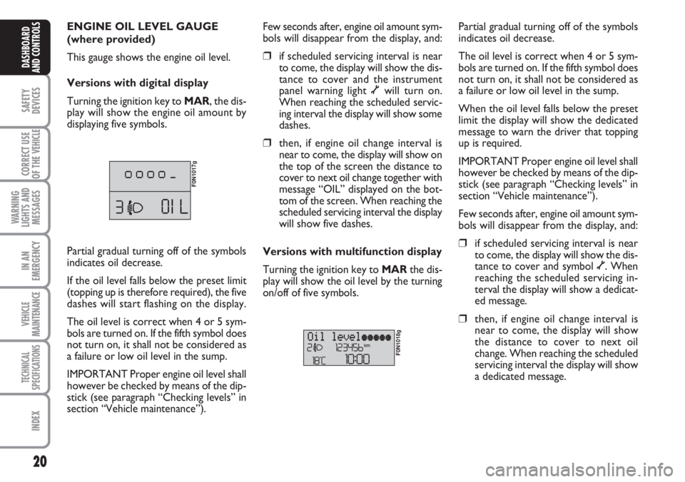
Turning the ignition key to MAR, the dis-
play will show the engine oil amount by
displaying five symbols.
F0N1017g
Few seconds after, engine oil amount sym-
bols will disappear from the display, and:
❒if scheduled servicing interval is near
to come, the display will show the dis-
tance to cover and the instrument
panel warning light õwill turn on.
When reaching the scheduled servic-
ing interval the display will show some
dashes.
❒then, if engine oil change interval is
near to come, the display will show on
the top of the screen the distance to
cover to next oil change together with
message “OIL” displayed on the bot-
tom of the screen. When reaching the
scheduled servicing interval the display
will show five dashes.
Versions with multifunction display
Turning the ignition key to MARthe dis-
play will show the oil level by the turning
on/off of five symbols.
F0N1018g
Partial gradual turning off of the symbols
indicates oil decrease.
The oil level is correct when 4 or 5 sym-
bols are turned on. If the fifth symbol does
not turn on, it shall not be considered as
a failure or low oil level in the sump.
When the oil level falls below the preset
limit the display will show the dedicated
message to warn the driver that topping
up is required.
IMPORTANT Proper engine oil level shall
however be checked by means of the dip-
stick (see paragraph “Checking levels” in
section “Vehicle maintenance”).
Few seconds after, engine oil amount sym-
bols will disappear from the display, and:
❒if scheduled servicing interval is near
to come, the display will show the dis-
tance to cover and symbol õ. When
reaching the scheduled servicing in-
terval the display will show a dedicat-
ed message.
❒then, if engine oil change interval is
near to come, the display will show
the distance to cover to next oil
change. When reaching the scheduled
servicing interval the display will show
a dedicated message. Partial gradual turning off of the symbols
indicates oil decrease.
If the oil level falls below the preset limit
(topping up is therefore required), the five
dashes will start flashing on the display.
The oil level is correct when 4 or 5 sym-
bols are turned on. If the fifth symbol does
not turn on, it shall not be considered as
a failure or low oil level in the sump.
IMPORTANT Proper engine oil level shall
however be checked by means of the dip-
stick (see paragraph “Checking levels” in
section “Vehicle maintenance”).
Page 22 of 282
21
SAFETY
DEVICES
CORRECT USE
OF THE
VEHICLE
WARNING
LIGHTS AND
MESSAGES
IN AN
EMERGENCY
VEHICLE
MAINTENANCE
TECHNICAL
SPECIFICATIONS
INDEX
DASHBOARD
AND CONTROLS
DIGITAL DISPLAY
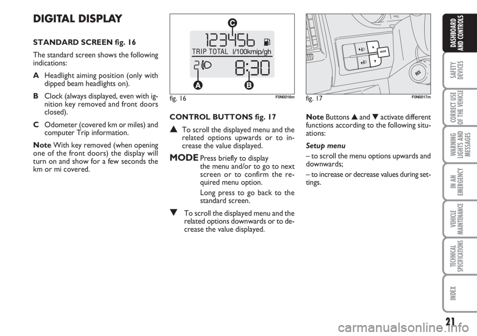
STANDARD SCREEN fig. 16
The standard screen shows the following
indications:
AHeadlight aiming position (only with
dipped beam headlights on).
BClock (always displayed, even with ig-
nition key removed and front doors
closed).
COdometer (covered km or miles) and
computer Trip information.
NoteWith key removed (when opening
one of the front doors) the display will
turn on and show for a few seconds the
km or mi covered.CONTROL BUTTONS fig. 17
▲To scroll the displayed menu and the
related options upwards or to in-
crease the value displayed.
MODEPress briefly to display
the menu and/or to go to next
screen or to confirm the re-
quired menu option.
Long press to go back to the
standard screen.
▼To scroll the displayed menu and the
related options downwards or to de-
crease the value displayed.NoteButtons ▲and ▼activate different
functions according to the following situ-
ations:
Setup menu
– to scroll the menu options upwards and
downwards;
– to increase or decrease values during set-
tings.
fig. 16F0N0016mfig. 17F0N0017m
Page 27 of 282
26
SAFETY
DEVICES
CORRECT USE
OF THE
VEHICLE
WARNING
LIGHTS AND
MESSAGES
IN AN
EMERGENCY
VEHICLE
MAINTENANCE
TECHNICAL
SPECIFICATIONS
INDEX
DASHBOARD
AND CONTROLS
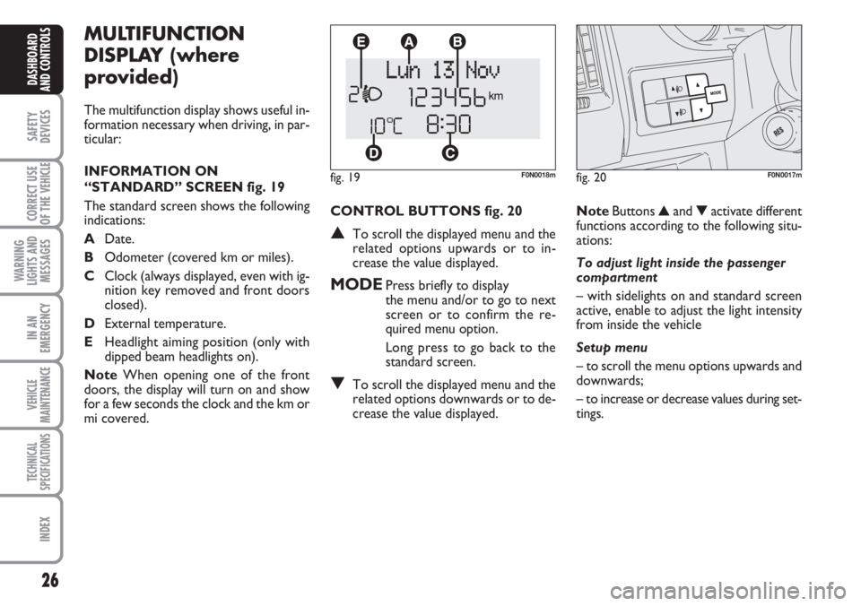
CONTROL BUTTONS fig. 20
▲To scroll the displayed menu and the
related options upwards or to in-
crease the value displayed.
MODEPress briefly to display
the menu and/or to go to next
screen or to confirm the re-
quired menu option.
Long press to go back to the
standard screen.
▼To scroll the displayed menu and the
related options downwards or to de-
crease the value displayed.
MULTIFUNCTION
DISPLAY (where
provided)
The multifunction display shows useful in-
formation necessary when driving, in par-
ticular:
INFORMATION ON
“STANDARD” SCREEN fig. 19
The standard screen shows the following
indications:
ADate.
BOdometer (covered km or miles).
CClock (always displayed, even with ig-
nition key removed and front doors
closed).
DExternal temperature.
EHeadlight aiming position (only with
dipped beam headlights on).
NoteWhen opening one of the front
doors, the display will turn on and show
for a few seconds the clock and the km or
mi covered.
fig. 19F0N0018m
NoteButtons ▲and ▼activate different
functions according to the following situ-
ations:
To adjust light inside the passenger
compartment
– with sidelights on and standard screen
active, enable to adjust the light intensity
from inside the vehicle
Setup menu
– to scroll the menu options upwards and
downwards;
– to increase or decrease values during set-
tings.
fig. 20F0N0017m
Page 34 of 282
33
SAFETY
DEVICES
CORRECT USE
OF THE
VEHICLE
WARNING
LIGHTS AND
MESSAGES
IN AN
EMERGENCY
VEHICLE
MAINTENANCE
TECHNICAL
SPECIFICATIONS
INDEX
DASHBOARD
AND CONTROLS
Adjusting the button volume
(Button Vol.)
With this function the volume of the
roger-beep accompanying the activation
of buttons MODE, ▲and ▼can be ad-
justed according to 8 levels.
To adjust the volume proceed as follows:
– briefly press button MODE: the previ-
ously set volume “level” will flash on the
display;
– press button ▲or ▼for setting;
– briefly press button MODEto go back
to the menu screen or press the button
for long to go back to the standard screen
without storing settings.S.B.R. buzzer reactivation
(Belt Buzzer)
This function can be only displayed after
Fiat Dealership has deactivated the S.B.R.
system (see paragraph “S.B.R. system” in
section “Safety devices”).
Scheduled Servicing (Service)
Through this function it is possible to dis-
play information connected to proper ve-
hicle servicing.
Proceed as follows:
– briefly press button MODE: service in
km or mi, according to previous setting,
will be displayed (see paragraph “Units”);
– briefly press button MODEto go back
to the menu screen or press the button
for long to go back to the standard screen.NoteThe “Service schedule” plans dif-
ferent service intervals according to en-
gine models; service interval is displayed
automatically, with the ignition key at
MAR, starting from 2,000 km (or 1,240
mi) from this deadline and it is shown again
every 200 km (or 124 mi). Oil change
warning messages are displayed in the
same way. Use buttons ▲and ▼to dis-
play alternately service schedule info and
engine oil change info. Below 200 km ser-
vicing indications are displayed more fre-
quently. Service indications will be dis-
played in km or mi according to previous
unit setting. When a programmed main-
tenance interval (coupon) is near to come,
turning the ignition key to MAR, the dis-
play will show the message “Service” fol-
lowed by the number of km/mi to go be-
fore vehicle servicing. Contact a Fiat Deal-
ership to carry out any service operation
provided by the “Service schedule” and to
reset the display.
Page 36 of 282
35
SAFETY
DEVICES
CORRECT USE
OF THE
VEHICLE
WARNING
LIGHTS AND
MESSAGES
IN AN
EMERGENCY
VEHICLE
MAINTENANCE
TECHNICAL
SPECIFICATIONS
INDEX
DASHBOARD
AND CONTROLS
TRIP COMPUTER
General features
The “Trip computer” displays information
(with ignition key at MAR), relating to the
operating status of the vehicle. This func-
tion comprises two separate and inde-
pendent trips: “Trip A” and “Trip B” con-
cerning the “complete mission” of the ve-
hicle (journey).
Both functions are resettable (reset - start
of new mission).
“Trip A” shall be used to display the fig-
ures relating to:
– External temperature
– Range
– Trip distance
– Average consumption
– Instant consumption
– Average speed
– Travel time (driving time).“Trip B”, available on multifunction display
only, shall be used to display the figures
relating to:
– Trip distance B
– Average consumption B
– Average speed B
– Travel time B (driving time).
Note“Trip B” function can be excluded
(see paragraph “Trip B On/Off”). “Range”
and “Instant consumption” cannot be re-
set.
Values displayed
External temperature
It indicates the external temperature of
the driver compartment.
Range
This value shows the distance in km (or
mi) that the vehicle can still cover before
needing fuel, assuming that driving condi-
tions are kept unvaried. The display will
show “----” in the following cases:
– value lower than 50 km (or 30 mi)
– vehicle left parked with engine running
for long.
Trip distance
This value shows the distance covered
from the start of the new mission. Exit Menu
This is the last function that closes the cir-
cular setting cycle listed in the initial menu
screen.
Briefly press button MODEto go back to
the standard screen without storing set-
tings.
Press button ▼to return to the first menu
option (Speed Beep).
Page 37 of 282
36
SAFETY
DEVICES
CORRECT USE
OF THE
VEHICLE
WARNING
LIGHTS AND
MESSAGES
IN AN
EMERGENCY
VEHICLE
MAINTENANCE
TECHNICAL
SPECIFICATIONS
INDEX
DASHBOARD
AND CONTROLS
Average consumption
This value shows the average consump-
tion from the start of the new mission.
Instant consumption
This value shows instant fuel consumption
(this value is updated second by second).
If parking the vehicle with engine on,
the display will show “----”.
Average speed
This value shows the vehicle average
speed as a function of the overall time
elapsed since the start of the new mission.
Travel time
This value shows the time elapsed since
the start of the new mission.
IMPORTANT Lacking information, Trip
computer values are displayed with “----”.
When normal operating condition is re-
set, calculation of different units will
restart regularly. Values displayed before
the failure will not be reset.
fig. 22F0N0019m
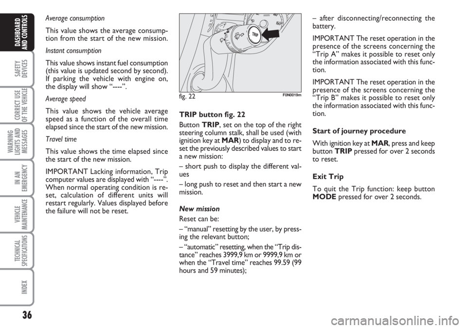
TRIP button fig. 22
Button TRIP, set on the top of the right
steering column stalk, shall be used (with
ignition key at MAR) to display and to re-
set the previously described values to start
a new mission:
– short push to display the different val-
ues
– long push to reset and then start a new
mission.
New mission
Reset can be:
– “manual” resetting by the user, by press-
ing the relevant button;
– “automatic” resetting, when the “Trip dis-
tance” reaches 3999,9 km or 9999,9 km or
when the “Travel time” reaches 99.59 (99
hours and 59 minutes);– after disconnecting/reconnecting the
battery.
IMPORTANT The reset operation in the
presence of the screens concerning the
“Trip A” makes it possible to reset only
the information associated with this func-
tion.
IMPORTANT The reset operation in the
presence of the screens concerning the
“Trip B” makes it possible to reset only
the information associated with this func-
tion.
Start of journey procedure
With ignition key at MAR, press and keep
button TRIPpressed for over 2 seconds
to reset.
Exit Trip
To quit the Trip function: keep button
MODEpressed for over 2 seconds.
Page 41 of 282
40
SAFETY
DEVICES
CORRECT USE
OF THE
VEHICLE
WARNING
LIGHTS AND
MESSAGES
IN AN
EMERGENCY
VEHICLE
MAINTENANCE
TECHNICAL
SPECIFICATIONS
INDEX
DASHBOARD
AND CONTROLS
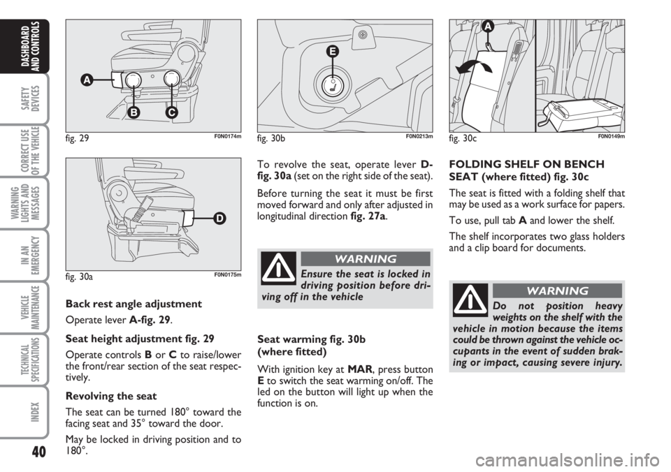
Back rest angle adjustment
Operate lever A-fig. 29.
Seat height adjustment fig. 29
Operate controls Bor Cto raise/lower
the front/rear section of the seat respec-
tively.
Revolving the seat
The seat can be turned 180° toward the
facing seat and 35° toward the door.
May be locked in driving position and to
180°.
fig. 29F0N0174m
fig. 30aF0N0175m
To revolve the seat, operate lever D-
fig. 30a(set on the right side of the seat).
Before turning the seat it must be first
moved forward and only after adjusted in
longitudinal direction fig. 27a.
fig. 30bF0N0213m
Ensure the seat is locked in
driving position before dri-
ving off in the vehicle
WARNING
Seat warming fig. 30b
(where fitted)
With ignition key at MAR, press button
Eto switch the seat warming on/off. The
led on the button will light up when the
function is on.
fig. 30cF0N0149m
FOLDING SHELF ON BENCH
SEAT (where fitted) fig. 30c
The seat is fitted with a folding shelf that
may be used as a work surface for papers.
To use, pull tab Aand lower the shelf.
The shelf incorporates two glass holders
and a clip board for documents.
Do not position heavy
weights on the shelf with the
vehicle in motion because the items
could be thrown against the vehicle oc-
cupants in the event of sudden brak-
ing or impact, causing severe injury.
WARNING
Page 47 of 282
46
SAFETY
DEVICES
CORRECT USE
OF THE
VEHICLE
WARNING
LIGHTS AND
MESSAGES
IN AN
EMERGENCY
VEHICLE
MAINTENANCE
TECHNICAL
SPECIFICATIONS
INDEX
DASHBOARD
AND CONTROLS
Folding
When required (for example when the
mirror causes difficulty in narrow spaces)
it is possible to fold the mirror moving it
from position 1-fig. 40to position 2.
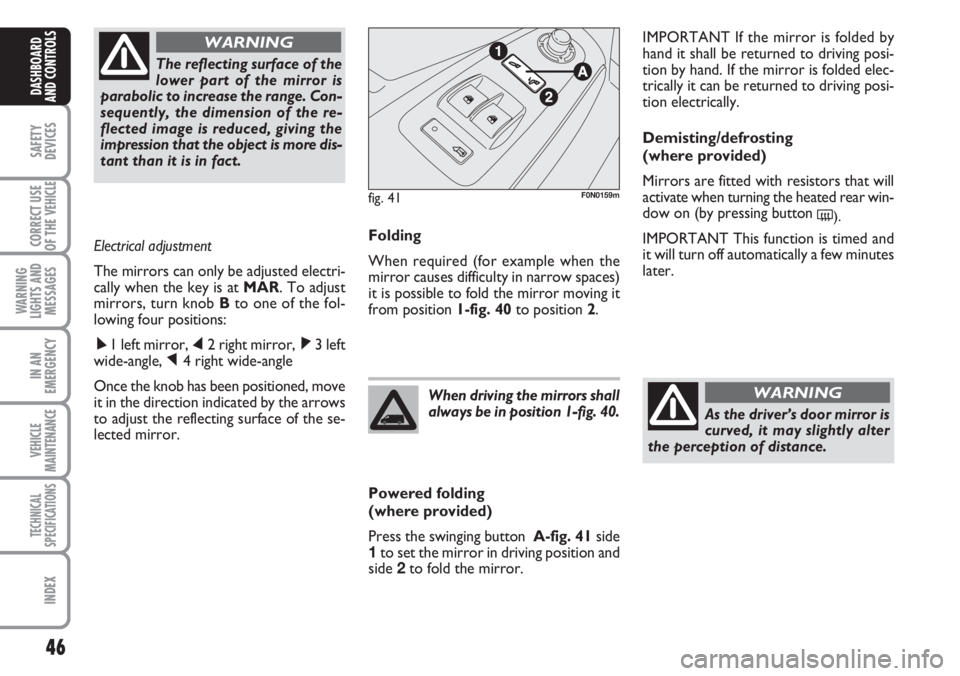
Powered folding
(where provided)
Press the swinging button A-fig. 41side
1to set the mirror in driving position and
side 2to fold the mirror.When driving the mirrors shall
always be in position 1-fig. 40.
As the driver’s door mirror is
curved, it may slightly alter
the perception of distance.
WARNING
IMPORTANT If the mirror is folded by
hand it shall be returned to driving posi-
tion by hand. If the mirror is folded elec-
trically it can be returned to driving posi-
tion electrically.
Demisting/defrosting
(where provided)
Mirrors are fitted with resistors that will
activate when turning the heated rear win-
dow on (by pressing button
().
IMPORTANT This function is timed and
it will turn off automatically a few minutes
later. The reflecting surface of the
lower part of the mirror is
parabolic to increase the range. Con-
sequently, the dimension of the re-
flected image is reduced, giving the
impression that the object is more dis-
tant than it is in fact.
WARNING
Electrical adjustment
The mirrors can only be adjusted electri-
cally when the key is at MAR. To adjust
mirrors, turn knob Bto one of the fol-
lowing four positions:
ÿ1 left mirror, ⁄2 right mirror, ¤3 left
wide-angle, Ÿ4 right wide-angle
Once the knob has been positioned, move
it in the direction indicated by the arrows
to adjust the reflecting surface of the se-
lected mirror.
fig. 41F0N0159m
Page 75 of 282
74
SAFETY
DEVICES
CORRECT USE
OF THE
VEHICLE
WARNING
LIGHTS AND
MESSAGES
IN AN
EMERGENCY
VEHICLE
MAINTENANCE
TECHNICAL
SPECIFICATIONS
INDEX
DASHBOARD
AND CONTROLS
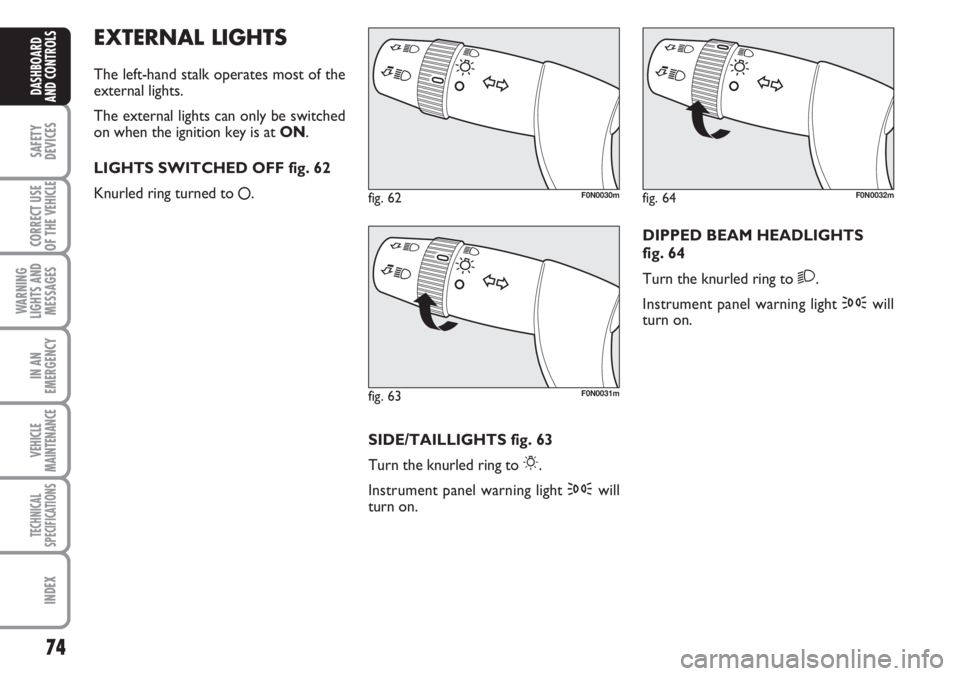
EXTERNAL LIGHTS
The left-hand stalk operates most of the
external lights.
The external lights can only be switched
on when the ignition key is at ON.
LIGHTS SWITCHED OFF fig. 62
Knurled ring turned to
å.
fig. 62F0N0030m
fig. 63F0N0031m
fig. 64F0N0032m
SIDE/TAILLIGHTS fig. 63
Turn the knurled ring to
6.
Instrument panel warning light 3will
turn on.DIPPED BEAM HEADLIGHTS
fig. 64
Turn the knurled ring to
2.
Instrument panel warning light 3will
turn on.