set clock FIAT DUCATO 2007 Owner handbook (in English)
[x] Cancel search | Manufacturer: FIAT, Model Year: 2007, Model line: DUCATO, Model: FIAT DUCATO 2007Pages: 282, PDF Size: 4.49 MB
Page 22 of 282
21
SAFETY
DEVICES
CORRECT USE
OF THE
VEHICLE
WARNING
LIGHTS AND
MESSAGES
IN AN
EMERGENCY
VEHICLE
MAINTENANCE
TECHNICAL
SPECIFICATIONS
INDEX
DASHBOARD
AND CONTROLS
DIGITAL DISPLAY
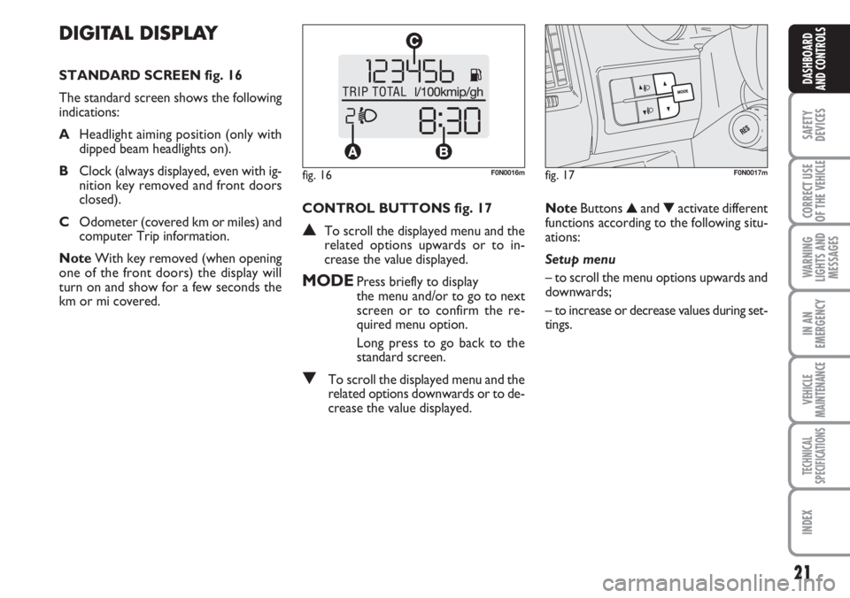
STANDARD SCREEN fig. 16
The standard screen shows the following
indications:
AHeadlight aiming position (only with
dipped beam headlights on).
BClock (always displayed, even with ig-
nition key removed and front doors
closed).
COdometer (covered km or miles) and
computer Trip information.
NoteWith key removed (when opening
one of the front doors) the display will
turn on and show for a few seconds the
km or mi covered.CONTROL BUTTONS fig. 17
▲To scroll the displayed menu and the
related options upwards or to in-
crease the value displayed.
MODEPress briefly to display
the menu and/or to go to next
screen or to confirm the re-
quired menu option.
Long press to go back to the
standard screen.
▼To scroll the displayed menu and the
related options downwards or to de-
crease the value displayed.NoteButtons ▲and ▼activate different
functions according to the following situ-
ations:
Setup menu
– to scroll the menu options upwards and
downwards;
– to increase or decrease values during set-
tings.
fig. 16F0N0016mfig. 17F0N0017m
Page 23 of 282
22
SAFETY
DEVICES
CORRECT USE
OF THE
VEHICLE
WARNING
LIGHTS AND
MESSAGES
IN AN
EMERGENCY
VEHICLE
MAINTENANCE
TECHNICAL
SPECIFICATIONS
INDEX
DASHBOARD
AND CONTROLS
SETUP MENU fig. 18
The menu comprises a series of functions
arranged in a “circular fashion” which can
be selected through buttons ▲and ▼to
access the different select operations and
settings (setup) given in the following para-
graphs.
The setup menu can be activated by press-
ing briefly button MODE.
Single presses on buttons ▲and ▼will
scroll the setup menu options.
Handling modes differ with each other ac-
cording to the characteristic of the option
selected.Selecting a menu option
– press briefly button MODEto select
the menu option to set;
– press buttons ▲and ▼(by single press-
es) to select the new setting;
– press briefly button MODEto store the
new setting and to go back to the previ-
ously selected menu option.
Selecting “Set Clock”
– briefly press button MODEto select
the first value to change (hours);
– press buttons ▲and ▼(by single press-
es) to select the new setting;
– briefly press button MODEto store the
new setting and to go to the next setup
menu option (minutes);
– after setting the values with the same
procedure, you’ll go back to the menu op-
tion previously selected.Press the button MODE for long
– to quit the set up menu if you are in the
menu;
– to quit the displayed menu if you are set-
ting an option;
– to save only the settings stored yet (and
confirmed by pressing button MODE).
The setup menu displaying is timed; when
quitting the menu due to timing expiry, on-
ly settings stored yet by the user (and con-
firmed by pressing briefly button MODE)
will be saved.
Page 25 of 282
24
SAFETY
DEVICES
CORRECT USE
OF THE
VEHICLE
WARNING
LIGHTS AND
MESSAGES
IN AN
EMERGENCY
VEHICLE
MAINTENANCE
TECHNICAL
SPECIFICATIONS
INDEX
DASHBOARD
AND CONTROLS
Setting the speed limit (SPEEd)
With this function it is possible to set the
vehicle speed limit (km/h or mph), when
this limit is exceeded the driver is imme-
diately alerted (see section “Warning lights
and messages”).
To set the speed limit, proceed as follows:
– briefly press button MODE, the display
will show the wording (SPEEd) and the
unit (km/h) or (mph) previously set;
– press button▲or ▼to select speed
limit activation (On) or deactivation
(OFF);
– if the function has been activated (On),
press buttons ▲or ▼to select the re-
quired speed limit and then press MODE
to confirm;
NoteThe possible setting is between 30
and 200 km/h, or between 20 and 125
mph depending on the unit set previous-
ly (see paragraph “Setting the distance unit
(Unit)”) described later. Every press on
button ▲/▼increases/decreases by 5
units. Keeping the button ▲/▼pressed
obtains the automatic fast increase or de-
crease. When you are near the required
setting complete adjustment by single
presses.
– briefly press button MODEto go back
to the menu screen or press the button
for long to go back to the standard screen
without storing settings.Setting the clock (Hour)
With this function it is possible to set the
clock.
To set the required unit proceed as fol-
lows:
– briefly press button MODE, “hours”
will flash on the display;
– press button ▲or ▼for setting;
– briefly press button MODE, “minutes”
will flash on the display;
– press button ▲or ▼for setting;
– briefly press button MODEto go back
to the menu screen or press the button
for long to go back to the standard screen
without storing settings.
Adjusting the buzzer volume
(bUZZ)
This function enables to adjust the volume
of the buzzer accompanying any fail-
ure/warning indication.
To adjust the volume proceed as follows:
– briefly press button MODE, the display
will show the wording (bUZZ);
– press button ▲or ▼to select the re-
quired volume (volume can be adjusted ac-
cording to 8 levels).
– briefly press button MODEto go back
to the menu screen or press the button
for long to go back to the standard screen
without storing settings.Setting the distance unit (Unit)
With this function it is possible to set the
unit.
To set the required unit proceed as fol-
lows:
– briefly press button MODE, the display
will show the wording (Unit) and the pre-
viously set unit (km) or (mi);
– press button ▲or ▼to select the re-
quired distance unit.
– briefly press button MODE
to go back
to the menu screen or press the button
for long to go back to the standard screen
without storing settings.
Page 27 of 282
26
SAFETY
DEVICES
CORRECT USE
OF THE
VEHICLE
WARNING
LIGHTS AND
MESSAGES
IN AN
EMERGENCY
VEHICLE
MAINTENANCE
TECHNICAL
SPECIFICATIONS
INDEX
DASHBOARD
AND CONTROLS
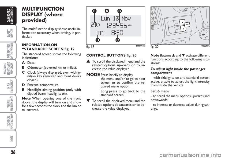
CONTROL BUTTONS fig. 20
▲To scroll the displayed menu and the
related options upwards or to in-
crease the value displayed.
MODEPress briefly to display
the menu and/or to go to next
screen or to confirm the re-
quired menu option.
Long press to go back to the
standard screen.
▼To scroll the displayed menu and the
related options downwards or to de-
crease the value displayed.
MULTIFUNCTION
DISPLAY (where
provided)
The multifunction display shows useful in-
formation necessary when driving, in par-
ticular:
INFORMATION ON
“STANDARD” SCREEN fig. 19
The standard screen shows the following
indications:
ADate.
BOdometer (covered km or miles).
CClock (always displayed, even with ig-
nition key removed and front doors
closed).
DExternal temperature.
EHeadlight aiming position (only with
dipped beam headlights on).
NoteWhen opening one of the front
doors, the display will turn on and show
for a few seconds the clock and the km or
mi covered.
fig. 19F0N0018m
NoteButtons ▲and ▼activate different
functions according to the following situ-
ations:
To adjust light inside the passenger
compartment
– with sidelights on and standard screen
active, enable to adjust the light intensity
from inside the vehicle
Setup menu
– to scroll the menu options upwards and
downwards;
– to increase or decrease values during set-
tings.
fig. 20F0N0017m
Page 31 of 282
30
SAFETY
DEVICES
CORRECT USE
OF THE
VEHICLE
WARNING
LIGHTS AND
MESSAGES
IN AN
EMERGENCY
VEHICLE
MAINTENANCE
TECHNICAL
SPECIFICATIONS
INDEX
DASHBOARD
AND CONTROLS
– if selecting “Mode”:briefly press button
MODE, “24h” or “12h” mode will flash
on the display;
– press button ▲or ▼to select “24h” or
“12h”.
After setting, briefly press button MODE
to go back to the submenu screen or
press the button for long to go back to the
main menu screen without storing set-
tings.
– press again button MODEfor long to
go back to the standard screen or to the
main menu according to the current menu
level. Set clock (Set time)
This function enables to set the clock
through two sub-menus: “Time” and
“Mode”.
Proceed as follows:
– briefly press button MODE, the display
will show the two sub-menus “Time” and
“Mode”;
– press button ▲or ▼to surf the two
sub-menus;
– select the required option and then
press button MODE;
– if selecting “Time”: briefly press button
MODE, “hours” will flash on the display;
– press button ▲or ▼for setting;
– briefly press button MODE, “minutes”
will flash on the display;
– press button ▲or ▼for setting;Set date (Set Date)
This function enables to update the date
(year - month - day).
To correct the date proceed as follows:
– briefly press button MODE, “day” will
flash on the display;
– press button ▲or ▼for setting;
– briefly press button MODE, “month”
will flash on the display;
– press button ▲or ▼for setting;
– briefly press button MODE, “year” will
flash on the display;
– press button ▲or ▼for setting.
NoteEvery press on button ▲or ▼in-
creases/decreases by 1 unit. Keeping the
button pressed obtains automatic fast in-
crease or decrease. When you are near
the required setting complete adjustment
by single presses.
– briefly press button MODEto go back
to the menu screen or press the button
for long to go back to the standard screen
without storing settings.
Page 59 of 282
58
SAFETY
DEVICES
CORRECT USE
OF THE
VEHICLE
WARNING
LIGHTS AND
MESSAGES
IN AN
EMERGENCY
VEHICLE
MAINTENANCE
TECHNICAL
SPECIFICATIONS
INDEX
DASHBOARD
AND CONTROLS
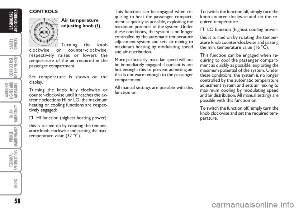
CONTROLS
Air temperature
adjusting knob (I)
temperatura
Turning the knob
clockwise or counter-clockwise,
respectively raises or lowers the
temperature of the air required in the
passenger compartment.
Set temperature is shown on the
display.
Turning the knob fully clockwise or
counter-clockwise until it reaches the ex-
treme selections HI or LO, the maximum
heating or cooling functions are respec-
tively engaged:
❒HI function (highest heating power):
this is turned on by rotating the temper-
ature knob clockwise and passing the max.
temperature value (32 °C).
This function can be engaged when re-
quiring to heat the passenger compart-
ment as quickly as possible, exploiting the
maximum potential of the system. Under
these conditions, the system is no longer
controlled by the automatic temperature
adjustment system and sets air mixing to
maximum heating by modulating speed
and air distribution.
More particularly, max. fan speed will not
be immediately engaged if coolant is not
hot enough; this to prevent admitting air
that is not warm enough to the passenger
compartment.
All manual settings are possible with this
function on.To switch the function off, simply turn the
knob counter-clockwise and set the re-
quired temperature.
❒LO function (highest cooling power:
this is turned on by rotating the temper-
ature knob counter-clockwise and passing
the min. temperature value (16 °C).
This function can be engaged when re-
quiring to cool the passenger compart-
ment as quickly as possible, exploiting the
maximum potential of the system. Under
these conditions, the system is no longer
controlled by the automatic temperature
adjustment system and sets air mixing to
maximum cooling by modulating speed
and air distribution. All manual settings are
possible with this function on.
To switch the function off, simply turn the
knob clockwise and set the required tem-
perature.
Page 69 of 282
68
SAFETY
DEVICES
CORRECT USE
OF THE
VEHICLE
WARNING
LIGHTS AND
MESSAGES
IN AN
EMERGENCY
VEHICLE
MAINTENANCE
TECHNICAL
SPECIFICATIONS
INDEX
DASHBOARD
AND CONTROLS
IMPORTANT The heater is equipped with
a thermal switch which cuts off the heater
in the event of overheating caused by low
or leaking coolant. In this case, press the
program selection button to start the
heater again after repairing the cooling sys-
tem fault and/or topping up the fluid.
The heater can turn itself off after engine
ignition or if the flame goes out. In this
case, turn the heater off manually and at-
tempt to turn it back on again. If you can-
not turn the heater on, contact a Fiat
Dealership.Turning the heater on
If an automatic climate control system is
fitted, the control unit sets air tempera-
ture and distribution when the parking
heater is turned on.
When a manual heater/climate control
system is fitted, to achieve peak heater
performance, check that the passenger
compartment heater/ventilation unit air
temperature knob is in “warm air” posi-
tion.
For preferential passenger compartment
preheating, turn the air distribution knob
to position
©.
For preferential windscreen demisting, set
the air distribution knob to position
-.
To obtain both functions, set the air dis-
tribution knob to position
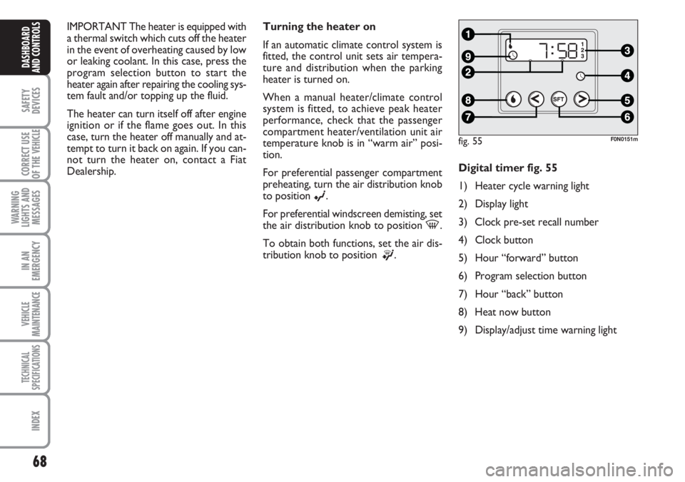
®.Digital timer fig. 55
1) Heater cycle warning light
2) Display light
3) Clock pre-set recall number
4) Clock button
5) Hour “forward” button
6) Program selection button
7) Hour “back” button
8) Heat now button
9) Display/adjust time warning light
fig. 55F0N0151m
Page 70 of 282
69
SAFETY
DEVICES
CORRECT USE
OF THE
VEHICLE
WARNING
LIGHTS AND
MESSAGES
IN AN
EMERGENCY
VEHICLE
MAINTENANCE
TECHNICAL
SPECIFICATIONS
INDEX
DASHBOARD
AND CONTROLS
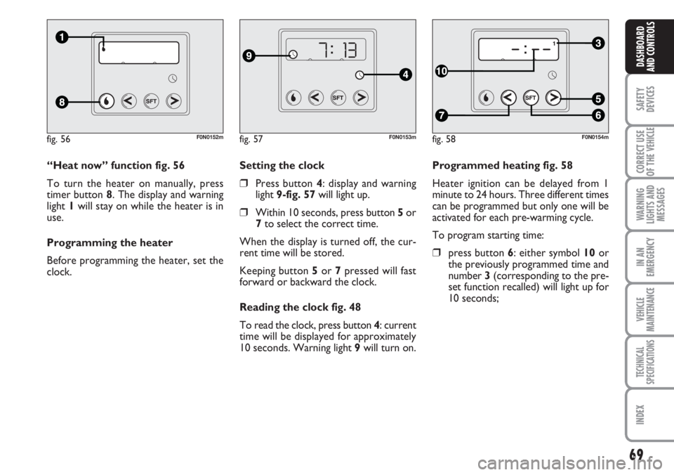
Programmed heating fig. 58
Heater ignition can be delayed from 1
minute to 24 hours. Three different times
can be programmed but only one will be
activated for each pre-warming cycle.
To program starting time:
❒press button 6: either symbol 10 or
the previously programmed time and
number 3 (corresponding to the pre-
set function recalled) will light up for
10 seconds; Setting the clock
❒Press button 4: display and warning
light 9-fig. 57will light up.
❒Within 10 seconds, press button 5or
7to select the correct time.
When the display is turned off, the cur-
rent time will be stored.
Keeping button 5or 7pressed will fast
forward or backward the clock.
Reading the clock fig. 48
To read the clock, press button 4: current
time will be displayed for approximately
10 seconds. Warning light 9will turn on. “Heat now” function fig. 56
To turn the heater on manually, press
timer button 8. The display and warning
light 1will stay on while the heater is in
use.
Programming the heater
Before programming the heater, set the
clock.
fig. 56F0N0152mfig. 57F0N0153mfig. 58F0N0154m
Page 86 of 282
85
SAFETY
DEVICES
CORRECT USE
OF THE
VEHICLE
WARNING
LIGHTS AND
MESSAGES
IN AN
EMERGENCY
VEHICLE
MAINTENANCE
TECHNICAL
SPECIFICATIONS
INDEX
DASHBOARD
AND CONTROLS
fig. 85F0N0127m
fig. 87F0N0050m
fig. 86F0N0049m
fig. 88F0N0051m
INTERIOR EQUIPMENT
UPPER ODDMENT
COMPARTMENT -
REFRIGERATED
COMPARTMENT
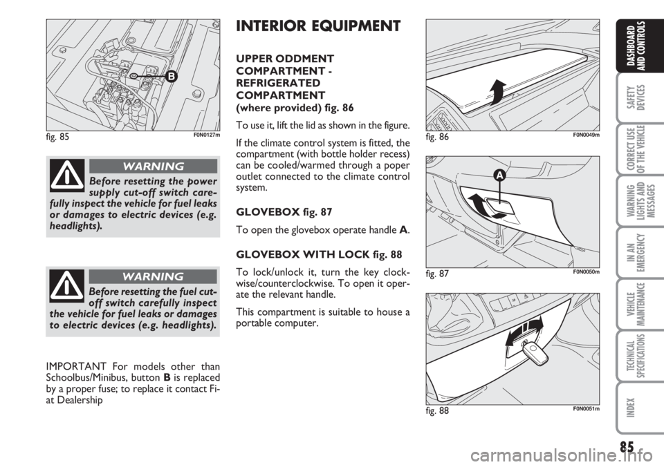
(where provided) fig. 86
To use it, lift the lid as shown in the figure.
If the climate control system is fitted, the
compartment (with bottle holder recess)
can be cooled/warmed through a poper
outlet connected to the climate control
system.
GLOVEBOX fig. 87
To open the glovebox operate handle A.
GLOVEBOX WITH LOCK fig. 88
To lock/unlock it, turn the key clock-
wise/counterclockwise. To open it oper-
ate the relevant handle.
This compartment is suitable to house a
portable computer.
Before resetting the power
supply cut-off switch care-
fully inspect the vehicle for fuel leaks
or damages to electric devices (e.g.
headlights).
WARNING
Before resetting the fuel cut-
off switch carefully inspect
the vehicle for fuel leaks or damages
to electric devices (e.g. headlights).
WARNING
IMPORTANT For models other than
Schoolbus/Minibus, button Bis replaced
by a proper fuse; to replace it contact Fi-
at Dealership
Page 94 of 282
93
SAFETY
DEVICES
CORRECT USE
OF THE
VEHICLE
WARNING
LIGHTS AND
MESSAGES
IN AN
EMERGENCY
VEHICLE
MAINTENANCE
TECHNICAL
SPECIFICATIONS
INDEX
DASHBOARD
AND CONTROLS
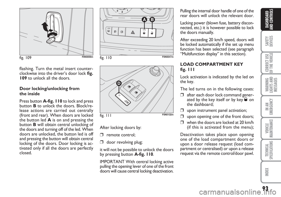
flashing. Turn the metal insert counter-
clockwise into the driver’s door lock fig.
109to unlock all the doors.
Door locking/unlocking from
the inside
Press button A-fig. 110to lock and press
button Bto unlock the doors. Block/re-
lease actions are carried out centrally
(front and rear). When doors are locked
the button led Ais on and pressing the
button Bwill obtain central unlocking of
the doors and turning off of the led. When
doors are unlocked, the button led is off
and pressing the button will obtain central
locking of the doors. Door locking is ac-
tivated only if all the doors are perfectly
closed.
fig. 109F0N0059mfig. 110F0N0047m
fig. 111F0N0132m
Pulling the internal door handle of one of the
rear doors will unlock the relevant door.
Lacking power (blown fuse, battery discon-
nected, etc.) it is however possible to lock
the doors manually.
After exceeding 20 km/h speed, doors will
be locked automatically if the set up menu
function has been selected (see paragraph
“Multifunction display” in this section).
LOAD COMPARTMENT KEY
fig. 111
Lock activation is indicated by the led on
the key.
The led turns on in the following cases:
❒after each door lock command gener-
ated by the key itself or by key Øon
the dashboard;
❒upon instrument panel activation;
❒upon opening one of the front doors;
❒when the doors are locked at 20 km/h
(if this is activated from the menu);
Deactivation takes place upon opening
one of the load compartment doors or
upon a door release request (load com-
partment or centralised) or upon a release
request via the remote control/door pawl. After locking doors by:
❒remote control;
❒door revolving plug;
it will not be possible to unlock the doors
by pressing button
A-fig. 110.
IMPORTANT With central locking active
pulling the opening lever of one of the front
doors will cause central locking deactivation.