set clock FIAT DUCATO 2007 Owner handbook (in English)
[x] Cancel search | Manufacturer: FIAT, Model Year: 2007, Model line: DUCATO, Model: FIAT DUCATO 2007Pages: 282, PDF Size: 4.49 MB
Page 162 of 282

161
WARNING
LIGHTS AND
MESSAGES
VEHICLE
MAINTENANCE
TECHNICAL
SPECIFICATIONS
INDEX
DASHBOARD
AND CONTROLS
SAFETY
DEVICES
CORRECT USE
OF THE
VEHICLE
IN AN
EMERGENCY
❒on versions with alloy wheels, remote
the press-fitted hub cap;
❒loosen one turn the bolts of the wheel
to change;
❒turn the ring nut to extend the jack
partially;
❒set the jack near the lifting support
close to the wheel to change in the
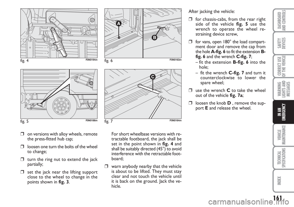
points shown in fig. 3. For short wheelbase versions with re-
tractable footboard, the jack shall be
set in the point shown in fig. 4and
shall be suitably directed (45°) to avoid
interference with the retractable foot-
board;
❒warn anybody nearby that the vehicle
is about to be lifted. They must stay
clear and not touch the vehicle until
it is back on the ground. Jack the ve-
hicle.
fig. 4F0N0194m
fig. 5F0N0186m
fig. 6F0N0163m
fig. 7F0N0164m
After jacking the vehicle:
❒for chassis-cabs, from the rear right
side of the vehicle fig. 5use the
wrench to operate the wheel re-
straining device screw,
❒for vans, open 180° the load compart-
ment door and remove the cap from
the hole A-fig. 6to fit the extension B-
fig. 6and the wrench C-fig. 7;
– fit the extension B-fig. 6into the
hole;
– fit the wrench C-fig. 7and turn it
counterclockwise to lower the
spare wheel;
❒use the wrench Cto take the wheel
out of the vehicle fig. 7a;
❒loosen the knob D , remove the sup-
port Eand release the wheel.
Page 168 of 282

167
WARNING
LIGHTS AND
MESSAGES
VEHICLE
MAINTENANCE
TECHNICAL
SPECIFICATIONS
INDEX
DASHBOARD
AND CONTROLS
SAFETY
DEVICES
CORRECT USE
OF THE
VEHICLE
IN AN
EMERGENCY
❒if at laest 3 bar pressure is read, re-
store proper pressure specified in
paragraph” Tyre pressure” in section
“Technical Specifications” (with engine
running and handbrake on) and
restart;
❒drive with the utmost care to the
nearest Fiat Dealership.
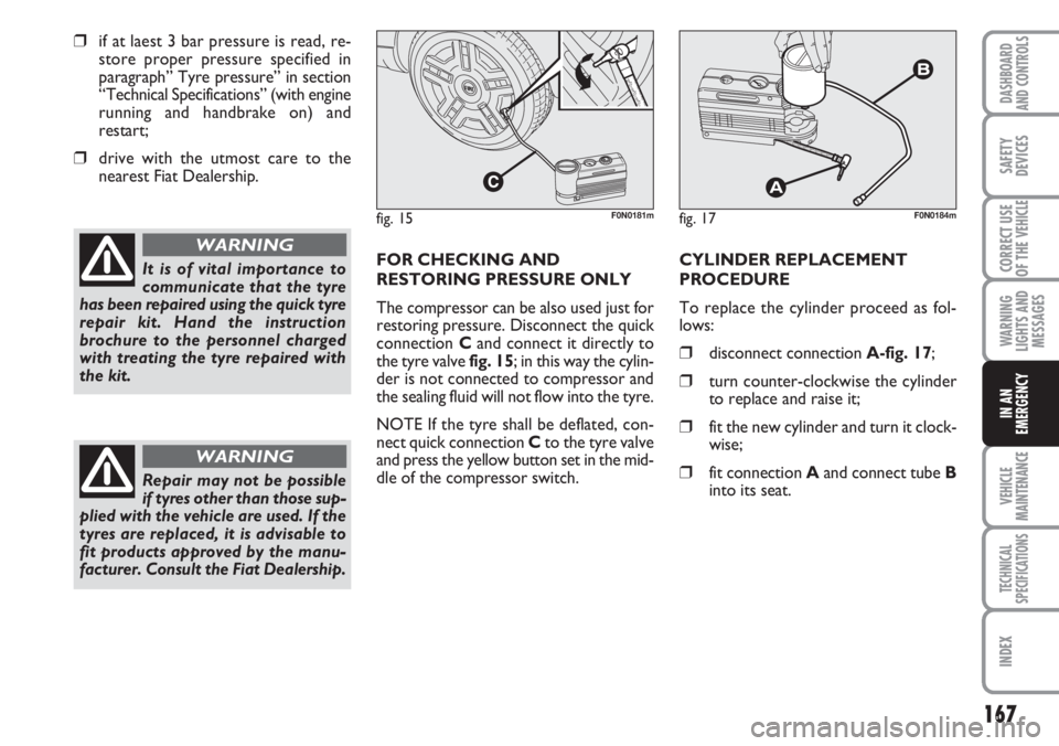
FOR CHECKING AND
RESTORING PRESSURE ONLY
The compressor can be also used just for
restoring pressure. Disconnect the quick
connection Cand connect it directly to
the tyre valve fig. 15; in this way the cylin-
der is not connected to compressor and
the sealing fluid will not flow into the tyre.
NOTE If the tyre shall be deflated, con-
nect quick connection Cto the tyre valve
and press the yellow button set in the mid-
dle of the compressor switch.CYLINDER REPLACEMENT
PROCEDURE
To replace the cylinder proceed as fol-
lows:
❒disconnect connection A-fig. 17;
❒turn counter-clockwise the cylinder
to replace and raise it;
❒fit the new cylinder and turn it clock-
wise;
❒fit connection Aand connect tube B
into its seat.
It is of vital importance to
communicate that the tyre
has been repaired using the quick tyre
repair kit. Hand the instruction
brochure to the personnel charged
with treating the tyre repaired with
the kit.
WARNING
fig. 17F0N0184mfig. 15F0N0181m
Repair may not be possible
if tyres other than those sup-
plied with the vehicle are used. If the
tyres are replaced, it is advisable to
fit products approved by the manu-
facturer. Consult the Fiat Dealership.
WARNING