clock FIAT DUCATO 2010 Owner handbook (in English)
[x] Cancel search | Manufacturer: FIAT, Model Year: 2010, Model line: DUCATO, Model: FIAT DUCATO 2010Pages: 286, PDF Size: 12.53 MB
Page 181 of 286
180
KNOWING
YOUR CAR
SAFETY
STARTING
AND
DRIVING
WARNING
LIGHTS AND
MESSAGES
IN AN
EMERGENCY
MAINTENANCE
AND CARE
TECHNICAL
SPECIFICATIONS
INDEX
E
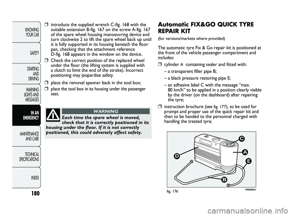
F0N0825mfig. 176
Automatic FIX&GO QUICK TYRE
REPAIR KIT
(for versions/markets where provided)
The automatic tyre Fix & Go repair kit is positioned at
the front of the vehicle passenger compartment and
includes:
❒cylinder A containing sealer and fitted with:
– a transparent filler pipe B;
– a black pressure restoring pipe E;
– an adhesive label C with the message “max.
80 km/h” to be applied in a position clearly visible
by the driver (on the dashboard) after repairing
the tyre;
❒instruction brochure (see fig. 177), to be used for
prompt and proper use of the quick repair kit and
then to be handed to the personnel charged with
handling the treated tyre;
Each time the spare wheel is moved,
check that it is correctly positioned in its
housing under the floor. If it is not correctly
positioned, this could adversely affect safety.
WARNING
❒introduce the supplied wrench C-fig. 168 with the
suitable extension B-fig. 167 on the screw A-fig. 167
of the spare wheel housing manoeuvring device and
turn clockwise 2 to lift the spare wheel back up until
it is fully supported in its housing beneath the floor
pan, checking that the attachment reference
D-fig. 168 appears in the window on the device.
❒Check the correct position of the replaced wheel
under the floor (the lifting system is supplied with
a clutch to limit the end of the stroke). Incorrect
positioning may jeopardise safety.
❒place the removal spanner back in the tool box;
❒place the tool box in its housing under the passenger
seat.
173-206 DUCATO LUM EN 8ed 27-10-2010 15:45 Pagina 180
Page 183 of 286
182
KNOWING
YOUR CAR
SAFETY
STARTING
AND
DRIVING
WARNING
LIGHTS AND
MESSAGES
IN AN
EMERGENCY
MAINTENANCE
AND CARE
TECHNICAL
SPECIFICATIONS
INDEX
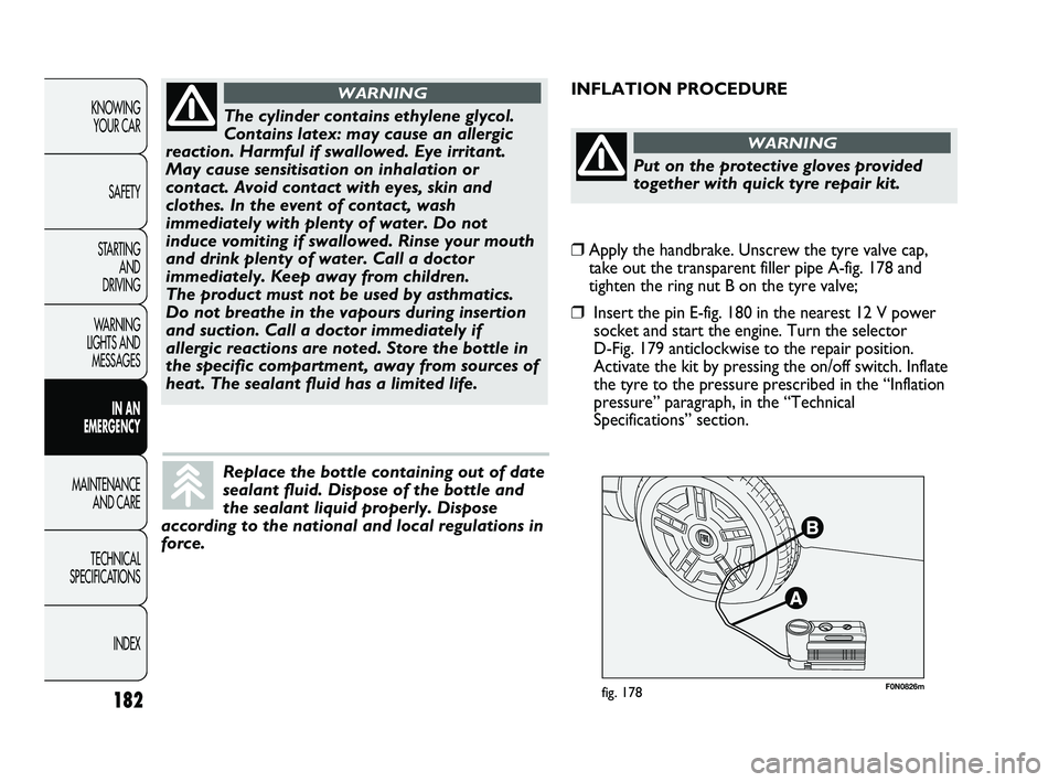
F0N0826mfig. 178
INFLATION PROCEDURE
The cylinder contains ethylene glycol.
Contains latex: may cause an allergic
reaction. Harmful if swallowed. Eye irritant.
May cause sensitisation on inhalation or
contact. Avoid contact with eyes, skin and
clothes. In the event of contact, wash
immediately with plenty of water. Do not
induce vomiting if swallowed. Rinse your mouth
and drink plenty of water. Call a doctor
immediately. Keep away from children.
The product must not be used by asthmatics.
Do not breathe in the vapours during insertion
and suction. Call a doctor immediately if
allergic reactions are noted. Store the bottle in
the specific compartment, away from sources of
heat. The sealant fluid has a limited life.
WARNING
Replace the bottle containing out of date
sealant fluid. Dispose of the bottle and
the sealant liquid properly. Dispose
according to the national and local regulations in
force.
Put on the protective gloves provided
together with quick tyre repair kit.
WARNING
❒Apply the handbrake. Unscrew the tyre valve cap,
take out the transparent filler pipe A-fig. 178 and
tighten the ring nut B on the tyre valve;
❒Insert the pin E-fig. 180 in the nearest 12 V power
socket and start the engine. Turn the selector
D-Fig. 179 anticlockwise to the repair position.
Activate the kit by pressing the on/off switch. Inflate
the tyre to the pressure prescribed in the “Inflation
pressure” paragraph, in the “Technical
Specifications” section.
173-206 DUCATO LUM EN 8ed 27-10-2010 15:45 Pagina 182
Page 185 of 286
184
KNOWING
YOUR CAR
SAFETY
STARTING
AND
DRIVING
WARNING
LIGHTS AND
MESSAGES
IN AN
EMERGENCY
MAINTENANCE
AND CARE
TECHNICAL
SPECIFICATIONS
INDEX
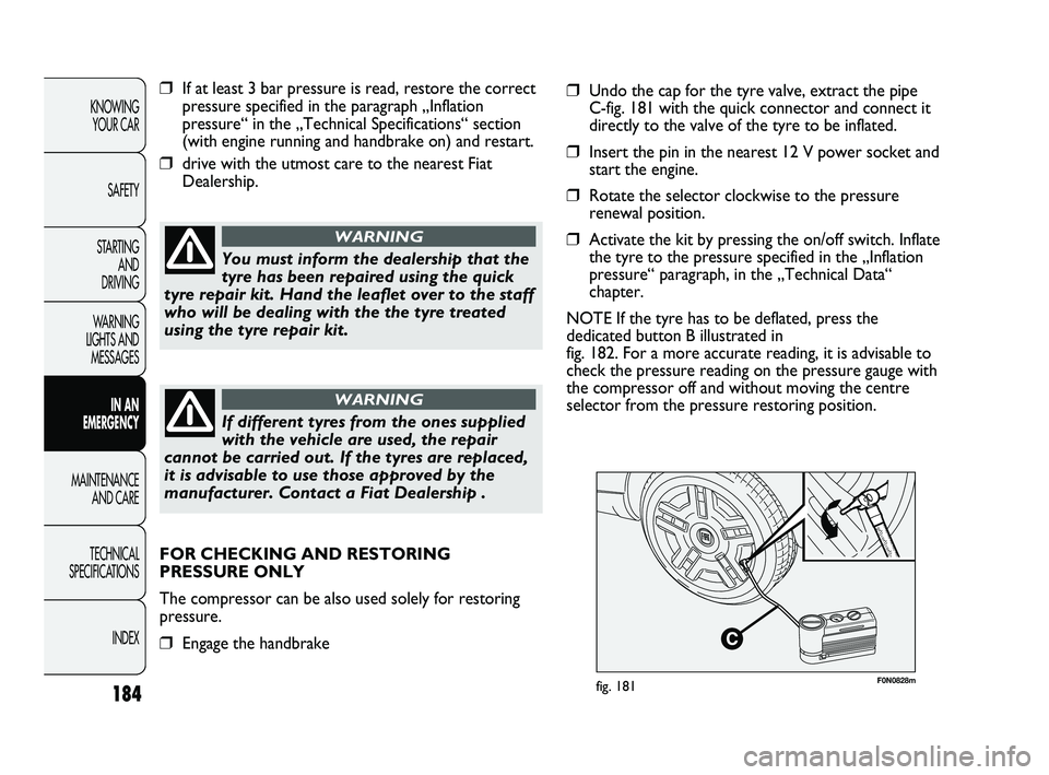
F0N0828mfig. 181
❒If at least 3 bar pressure is read, restore the correct
pressure specified in the paragraph „Inflation
pressure“ in the „Technical Specifications“ section
(with engine running and handbrake on) and restart.
❒drive with the utmost care to the nearest Fiat
Dealership.
You must inform the dealership that the
tyre has been repaired using the quick
tyre repair kit. Hand the leaflet over to the staff
who will be dealing with the the tyre treated
using the tyre repair kit.
WARNING
If different tyres from the ones supplied
with the vehicle are used, the repair
cannot be carried out. If the tyres are replaced,
it is advisable to use those approved by the
manufacturer. Contact a Fiat Dealership .
WARNING
❒Undo the cap for the tyre valve, extract the pipe
C-fig. 181 with the quick connector and connect it
directly to the valve of the tyre to be inflated.
❒Insert the pin in the nearest 12 V power socket and
start the engine.
❒Rotate the selector clockwise to the pressure
renewal position.
❒Activate the kit by pressing the on/off switch. Inflate
the tyre to the pressure specified in the „Inflation
pressure“ paragraph, in the „Technical Data“
chapter.
NOTE If the tyre has to be deflated, press the
dedicated button B illustrated in
fig. 182. For a more accurate reading, it is advisable to
check the pressure reading on the pressure gauge with
the compressor off and without moving the centre
selector from the pressure restoring position.
FOR CHECKING AND RESTORING
PRESSURE ONLY
The compressor can be also used solely for restoring
pressure.
❒Engage the handbrake
173-206 DUCATO LUM EN 8ed 27-10-2010 15:45 Pagina 184
Page 187 of 286
186
KNOWING
YOUR CAR
SAFETY
STARTING
AND
DRIVING
WARNING
LIGHTS AND
MESSAGES
IN AN
EMERGENCY
MAINTENANCE
AND CARE
TECHNICAL
SPECIFICATIONS
INDEX
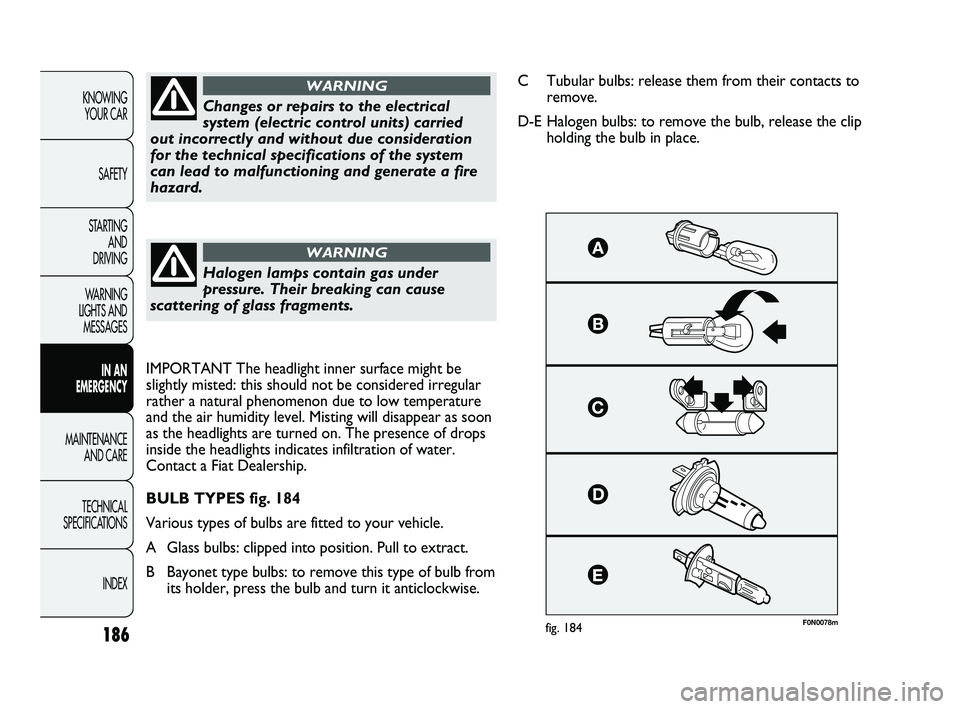
F0N0078mfig. 184
Changes or repairs to the electrical
system (electric control units) carried
out incorrectly and without due consideration
for the technical specifications of the system
can lead to malfunctioning and generate a fire
hazard.
WARNING
Halogen lamps contain gas under
pressure. Their breaking can cause
scattering of glass fragments.
WARNING
C Tubular bulbs: release them from their contacts to
remove.
D-E Halogen bulbs: to remove the bulb, release the clip
holding the bulb in place.
IMPORTANT The headlight inner surface might be
slightly misted: this should not be considered irregular
rather a natural phenomenon due to low temperature
and the air humidity level. Misting will disappear as soon
as the headlights are turned on. The presence of drops
inside the headlights indicates infiltration of water.
Contact a Fiat Dealership.
BULB TYPES fig. 184
Various types of bulbs are fitted to your vehicle.
A Glass bulbs: clipped into position. Pull to extract.
B Bayonet type bulbs: to remove this type of bulb from
its holder, press the bulb and turn it anticlockwise.
173-206 DUCATO LUM EN 8ed 27-10-2010 15:45 Pagina 186
Page 190 of 286
189
KNOWING
YOUR CAR
SAFETY
STARTING
AND
DRIVING
WARNING
LIGHTS AND
MESSAGES
IN AN
EMERGENCY
MAINTENANCE
AND CARE
TECHNICAL
SPECIFICATIONS
INDEX
F0N0082mfig. 187F0N0083mfig. 188
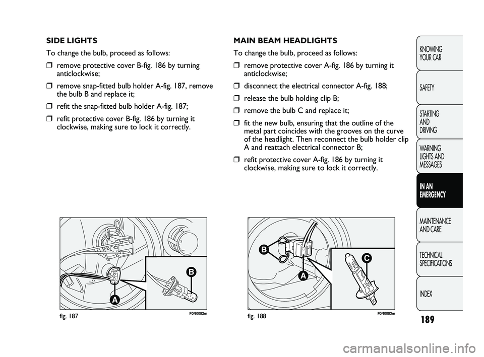
MAIN BEAM HEADLIGHTS
To change the bulb, proceed as follows:
❒remove protective cover A-fig. 186 by turning it
anticlockwise;
❒disconnect the electrical connector A-fig. 188;
❒release the bulb holding clip B;
❒remove the bulb C and replace it;
❒fit the new bulb, ensuring that the outline of the
metal part coincides with the grooves on the curve
of the headlight. Then reconnect the bulb holder clip
A and reattach electrical connector B;
❒refit protective cover A-fig. 186 by turning it
clockwise, making sure to lock it correctly. SIDE LIGHTS
To change the bulb, proceed as follows:
❒remove protective cover B-fig. 186 by turning
anticlockwise;
❒remove snap-fitted bulb holder A-fig. 187, remove
the bulb B and replace it;
❒refit the snap-fitted bulb holder A-fig. 187;
❒refit protective cover B-fig. 186 by turning it
clockwise, making sure to lock it correctly.
173-206 DUCATO LUM EN 8ed 27-10-2010 15:45 Pagina 189
Page 191 of 286
190
KNOWING
YOUR CAR
SAFETY
STARTING
AND
DRIVING
WARNING
LIGHTS AND
MESSAGES
IN AN
EMERGENCY
MAINTENANCE
AND CARE
TECHNICAL
SPECIFICATIONS
INDEX
F0N0081mfig. 189
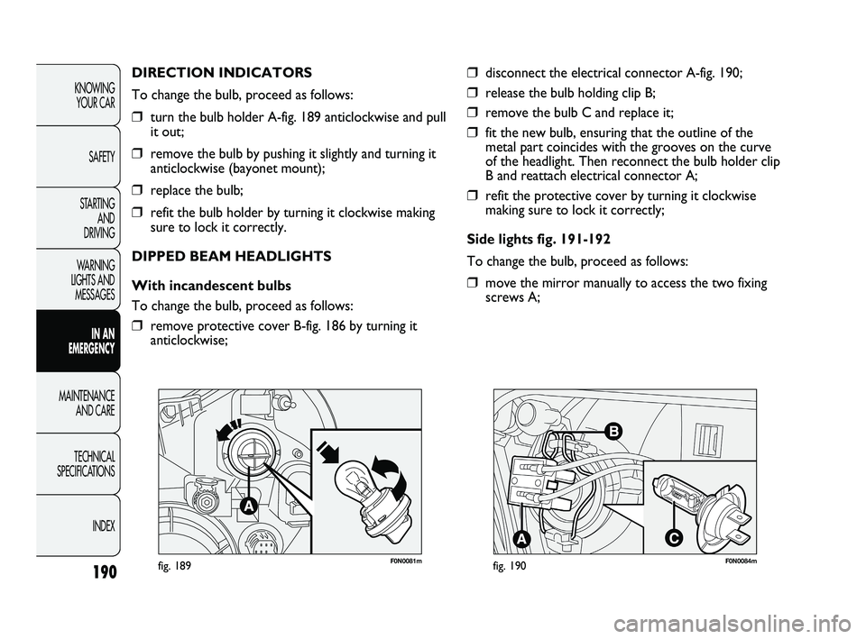
DIRECTION INDICATORS
To change the bulb, proceed as follows:
❒turn the bulb holder A-fig. 189 anticlockwise and pull
it out;
❒remove the bulb by pushing it slightly and turning it
anticlockwise (bayonet mount);
❒replace the bulb;
❒refit the bulb holder by turning it clockwise making
sure to lock it correctly.
DIPPED BEAM HEADLIGHTS
With incandescent bulbs
To change the bulb, proceed as follows:
❒remove protective cover B-fig. 186 by turning it
anticlockwise;
❒disconnect the electrical connector A-fig. 190;
❒release the bulb holding clip B;
❒remove the bulb C and replace it;
❒fit the new bulb, ensuring that the outline of the
metal part coincides with the grooves on the curve
of the headlight. Then reconnect the bulb holder clip
B and reattach electrical connector A;
❒refit the protective cover by turning it clockwise
making sure to lock it correctly;
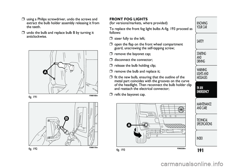
Side lights fig. 191-192
To change the bulb, proceed as follows:
❒move the mirror manually to access the two fixing
screws A;
F0N0084mfig. 190
173-206 DUCATO LUM EN 8ed 27-10-2010 15:45 Pagina 190
Page 192 of 286
191
KNOWING
YOUR CAR
SAFETY
STARTING
AND
DRIVING
WARNING
LIGHTS AND
MESSAGES
IN AN
EMERGENCY
MAINTENANCE
AND CARE
TECHNICAL
SPECIFICATIONS
INDEX
F0N0169mfig. 191
❒using a Philips screwdriver, undo the screws and
extract the bulb holder assembly releasing it from
the teeth.
❒undo the bulb and replace bulb B by turning it
anticlockwise.
F0N0170mfig. 192
FRONT FOG LIGHTS
(for versions/markets, where provided)
To replace the front fog light bulbs A-fig. 193 proceed as
follows:
❒steer fully to the left;
❒open the flap on the front wheel compartment
guard, unscrewing the self-tapping screw;
❒remove the bayonet cap;
❒disconnect the connector;
❒release the bulb holding clip;
❒remove the bulb and replace it;
❒fit the new bulb, ensuring that the outline of the
metal part coincides with the grooves on the curve
of the headlight. Then reconnect the bulb holder clip
and reattach the electrical connector;
❒refit the bayonet cap.
F0N0339mfig. 193
173-206 DUCATO LUM EN 8ed 27-10-2010 15:45 Pagina 191
Page 194 of 286
193
KNOWING
YOUR CAR
SAFETY
STARTING
AND
DRIVING
WARNING
LIGHTS AND
MESSAGES
IN AN
EMERGENCY
MAINTENANCE
AND CARE
TECHNICAL
SPECIFICATIONS
INDEX
F0N0088mfig. 196
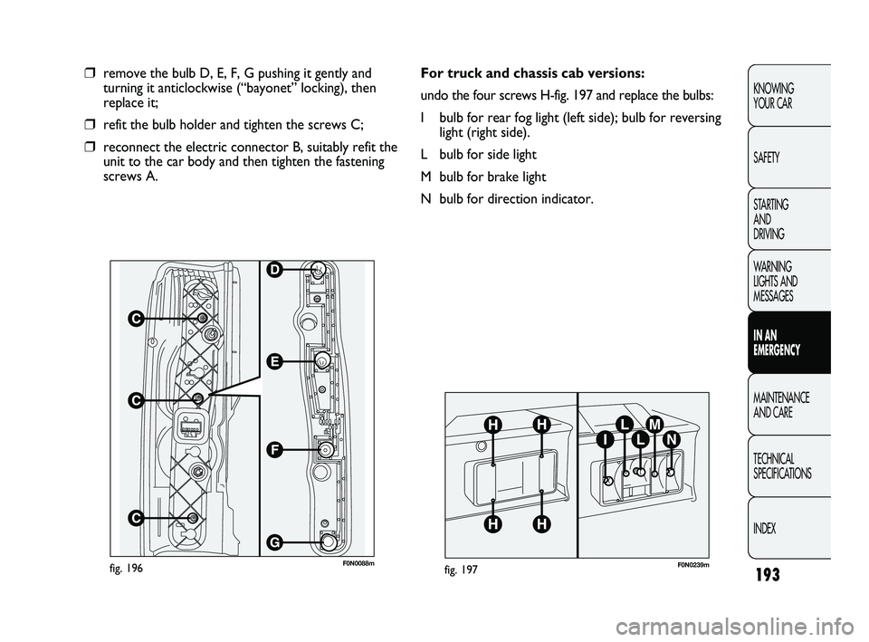
❒remove the bulb D, E, F, G pushing it gently and
turning it anticlockwise (“bayonet” locking), then
replace it;
❒refit the bulb holder and tighten the screws C;
❒reconnect the electric connector B, suitably refit the
unit to the car body and then tighten the fastening
screws A.
F0N0239mfig. 197
For truck and chassis cab versions:
undo the four screws H-fig. 197 and replace the bulbs:
I bulb for rear fog light (left side); bulb for reversing
light (right side).
L bulb for side light
M bulb for brake light
N bulb for direction indicator.
173-206 DUCATO LUM EN 8ed 27-10-2010 15:45 Pagina 193
Page 195 of 286
F0N0241mfig. 198
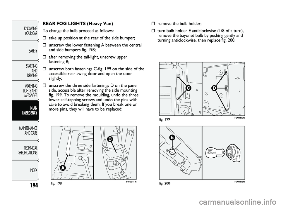
REAR FOG LIGHTS (Heavy Van)
To change the bulb proceed as follows:
❒take up position at the rear of the side bumper;
❒unscrew the lower fastening A between the central
and side bumpers fig. 198;
❒after removing the tail-light, unscrew upper
fastening B;
❒unscrew both fastenings C-fig. 199 on the side of the
accessible rear swing door and open the door
slightly;
❒unscrew the three side fastenings D on the panel
side, accessible after removing the side mounting
fig. 199. To remove the moulding, undo the three
lower self-tapping screws and undo the pins with
care to avoid breaking them. If you break one or
more pins, they will have to be replaced;
194
KNOWING
YOUR CAR
SAFETY
STARTING
AND
DRIVING
WARNING
LIGHTS AND
MESSAGES
IN AN
EMERGENCY
MAINTENANCE
AND CARE
TECHNICAL
SPECIFICATIONS
INDEX
F0N0242mfig. 199
F0N0243mfig. 200
❒remove the bulb holder;
❒turn bulb holder E anticlockwise (1/8 of a turn),
remove the bayonet bulb by pushing gently and
turning anticlockwise, then replace fig. 200.
173-206 DUCATO LUM EN 8ed 27-10-2010 15:45 Pagina 194
Page 207 of 286
206
KNOWING
YOUR CAR
SAFETY
STARTING
AND
DRIVING
WARNING
LIGHTS AND
MESSAGES
IN AN
EMERGENCY
MAINTENANCE
AND CARE
TECHNICAL
SPECIFICATIONS
INDEX
F0N0117mfig. 220F0N0135mfig. 218
F0N0136mfig. 219
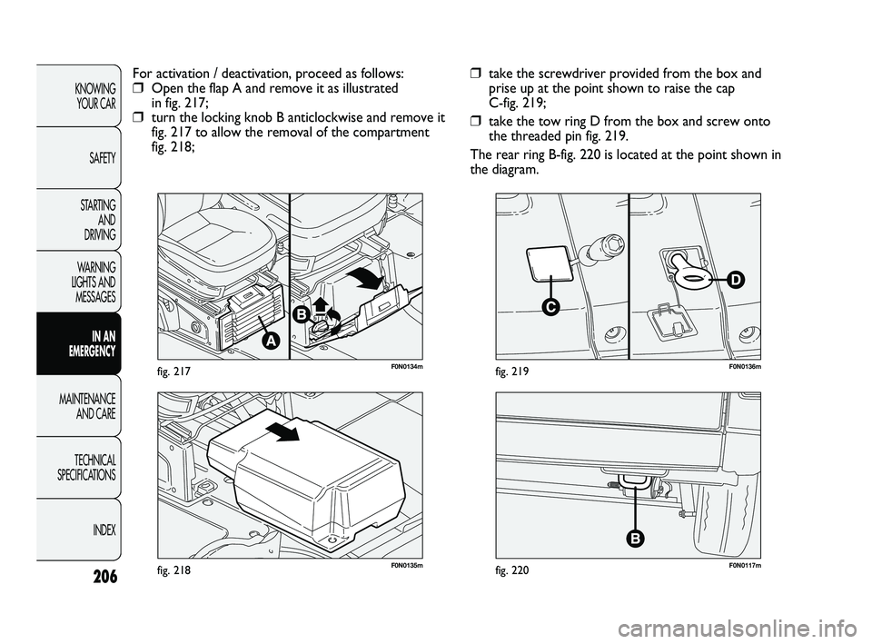
❒take the screwdriver provided from the box and
prise up at the point shown to raise the cap
C-fig. 219;
❒take the tow ring D from the box and screw onto
the threaded pin fig. 219.
The rear ring B-fig. 220 is located at the point shown in
the diagram. For activation / deactivation, proceed as follows:
❒Open the flap A and remove it as illustrated
in fig. 217;
❒turn the locking knob B anticlockwise and remove it
fig. 217 to allow the removal of the compartment
fig. 218;
F0N0134mfig. 217
173-206 DUCATO LUM EN 8ed 27-10-2010 15:45 Pagina 206