ECO mode FIAT DUCATO 2011 Owner handbook (in English)
[x] Cancel search | Manufacturer: FIAT, Model Year: 2011, Model line: DUCATO, Model: FIAT DUCATO 2011Pages: 287, PDF Size: 4.42 MB
Page 22 of 287
F0N0519mfig. 15F0N0017mfig. 16
NOTE When opening one of the front doors, the
display will turn on and show for a few seconds the
clock and the kilometres or miles covered.
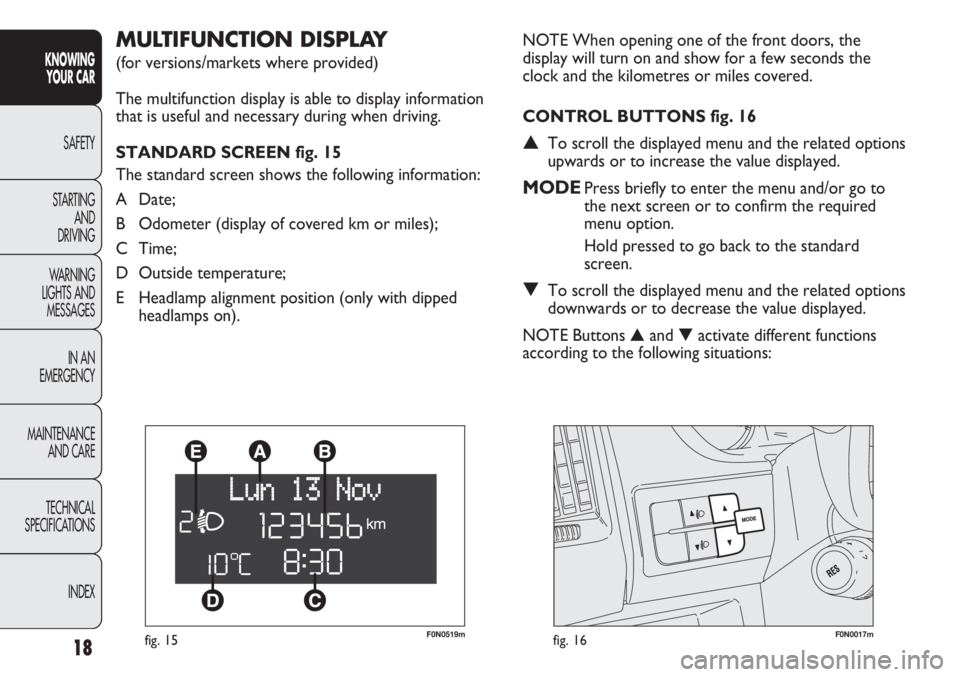
CONTROL BUTTONS fig. 16
▲To scroll the displayed menu and the related options
upwards or to increase the value displayed.
MODEPress briefly to enter the menu and/or go to
the next screen or to confirm the required
menu option.
Hold pressed to go back to the standard
screen.
▼To scroll the displayed menu and the related options
downwards or to decrease the value displayed.
NOTE Buttons ▲and ▼activate different functions
according to the following situations:
MULTIFUNCTION DISPLAY
(for versions/markets where provided)
The multifunction display is able to display information
that is useful and necessary during when driving.
STANDARD SCREEN fig. 15
The standard screen shows the following information:
A Date;
B Odometer (display of covered km or miles);
C Time;
D Outside temperature;
E Headlamp alignment position (only with dipped
headlamps on).
18
KNOWING
YOUR CAR
SAFETY
STARTING
AND
DRIVING
WARNING
LIGHTS AND
MESSAGES
IN AN
EMERGENCY
MAINTENANCE
AND CARE
TECHNICAL
SPECIFICATIONS
INDEX
Page 34 of 287
F0N0019mfig. 19
IMPORTANT If the reset operation is carried out when
“Trip B” is being displayed, only the information
associated with this function is reset.
Start of journey procedure
With the ignition key in the MAR-ON position, reset by
pressing the TRIP button and keeping it pressed for
more than 2 seconds.
Exit Trip
To quit the Trip function: keep button MODE pressed
for over 2 seconds. Trip time
This value shows the time elapsed since the start of the
new mission.
IMPORTANT In the absence of information, Trip
Computer values are displayed with “----”. When
normal operating conditions are restarted, calculation of
different units will restart regularly. The values displayed
before the failure will not be reset nor will a new
mission be started.
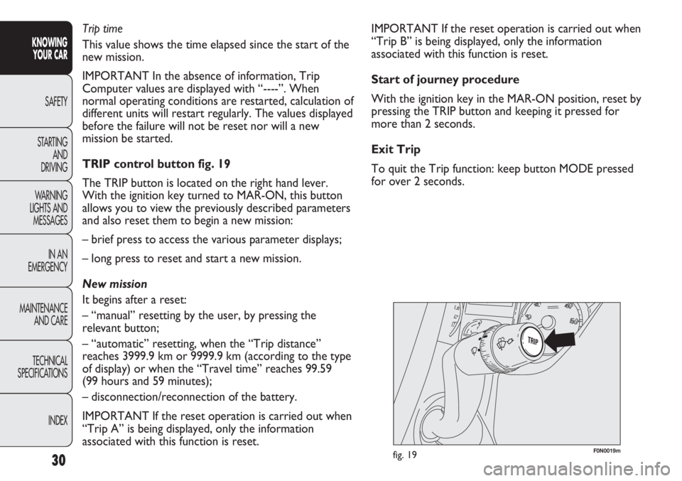
TRIP control button fig. 19
The TRIP button is located on the right hand lever.
With the ignition key turned to MAR-ON, this button
allows you to view the previously described parameters
and also reset them to begin a new mission:
– brief press to access the various parameter displays;
– long press to reset and start a new mission.
New mission
It begins after a reset:
– “manual” resetting by the user, by pressing the
relevant button;
– “automatic” resetting, when the “Trip distance”
reaches 3999.9 km or 9999.9 km (according to the type
of display) or when the “Travel time” reaches 99.59
(99 hours and 59 minutes);
– disconnection/reconnection of the battery.
IMPORTANT If the reset operation is carried out when
“Trip A” is being displayed, only the information
associated with this function is reset.
30
KNOWING
YOUR CAR
SAFETY
STARTING
AND
DRIVING
WARNING
LIGHTS AND
MESSAGES
IN AN
EMERGENCY
MAINTENANCE
AND CARE
TECHNICAL
SPECIFICATIONS
INDEX
Page 76 of 287
72
KNOWING
YOUR CAR
SAFETY
STARTING
AND
DRIVING
WARNING
LIGHTS AND
MESSAGES
IN AN
EMERGENCY
MAINTENANCE
AND CARE
TECHNICAL
SPECIFICATIONS
INDEX
F0N0039mfig. 71
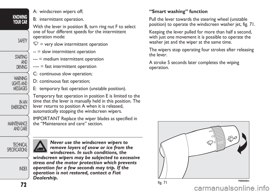
“Smart washing” function
Pull the lever towards the steering wheel (unstable
position) to operate the windscreen washer jet, fig. 71.
Keeping the lever pulled for more than half a second,
with just one movement it is possible to operate the
washer jet and the wiper at the same time.
The wipers stop operating four strokes after releasing
the lever.
A stroke 5 seconds later completes the wiping
operation. A: windscreen wipers off;
B: intermittent operation.
With the lever in position B, turn ring nut F to select
one of four different speeds for the intermittent
operation mode:
,= very slow intermittent operation
-- = slow intermittent operation
--- = medium intermittent operation
---- = fast intermittent operation
C: continuous slow operation;
D: continuous fast operation;
E: temporary fast operation (unstable position).
Temporary fast operation in position E is limited to the
time that the lever is manually held in this position. The
lever returns to position A when it is released,
automatically stopping the windscreen wipers.
IMPORTANT Replace the wiper blades as specified in
the “Maintenance and care” section.
Never use the windscreen wipers to
remove layers of snow or ice from the
windscreen. In such conditions, the
windscreen wipers may be subjected to excessive
stress and the motor protection which prevents
operation for a few seconds may trip. If the
operation is not restored, contact a Fiat
Dealership.
Page 81 of 287
77
KNOWING
YOUR CAR
SAFETY
STARTING
AND
DRIVING
WARNING
LIGHTS AND
MESSAGES
IN AN
EMERGENCY
MAINTENANCE
AND CARE
TECHNICAL
SPECIFICATIONS
INDEX
❒when opening one of the side doors for about
3 minutes;
❒when one of the doors is closed for a period of
about 10 seconds.
The timed delay period ends automatically when the
doors are locked.
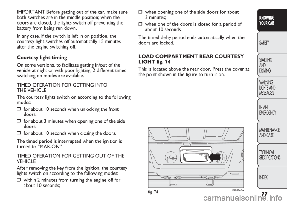
LOAD COMPARTMENT REAR COURTESY
LIGHT fig. 74
This is located above the rear door. Press the cover at
the point shown in the figure to turn it on. IMPORTANT Before getting out of the car, make sure
both switches are in the middle position; when the
doors are closed, the lights switch off preventing the
battery from being run down.
In any case, if the switch is left in on position, the
courtesy light switches off automatically 15 minutes
after the engine switching off.
Courtesy light timing
On some versions, to facilitate getting in/out of the
vehicle at night or with poor lighting, 2 different timed
switching on modes are available.
TIMED OPERATION FOR GETTING INTO
THE VEHICLE
The courtesy lights switch on according to the following
modes:
❒for about 10 seconds when unlocking the front
doors;
❒for about 3 minutes when opening one of the side
doors;
❒for about 10 seconds when closing the doors.
The timed period is interrupted when the ignition is
turned to “MAR-ON“.
TIMED OPERATION FOR GETTING OUT OF THE
VEHICLE
After removing the key from the ignition, the courtesy
lights switch on according to the following modes:
❒within 2 minutes from turning the engine off for
about 10 seconds;
F0N0042mfig. 74
Page 96 of 287
92
KNOWING
YOUR CAR
SAFETY
STARTING
AND
DRIVING
WARNING
LIGHTS AND
MESSAGES
IN AN
EMERGENCY
MAINTENANCE
AND CARE
TECHNICAL
SPECIFICATIONS
INDEX
F0N0217mfig. 105F0N0214mfig. 106
The rear view display is adjusted in mirror mode. When
not in use, it must be closed in the upper oddments
compartment console area.
ACTIVATION
The system is activated with the ignition on and reverse
engaged or by means of a dedicated button. If the
vehicle is in motion, e.g. during a reversing manoeuvre,
the system will operate up to a speed of 15 km/h and go
off when a speed of approximately 18 km/h is exceeded.
When reverse is deactivated, the image will appear on
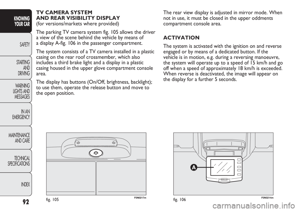
the display for a further 5 seconds. TV CAMERA SYSTEM
AND REAR VISIBILITY DISPLAY
(for versions/markets where provided)
The parking TV camera system fig. 105 allows the driver
a view of the scene behind the vehicle by means of
a display A-fig. 106 in the passenger compartment.
The system consists of a TV camera installed in a plastic
casing on the rear roof crossmember, which also
includes a third brake light and a display in a plastic
casing housed in the upper glove compartment console
area.
The display has buttons (On/Off, brightness, backlight);
to use them, operate the release button and move to
the open position.
Page 98 of 287
94
KNOWING
YOUR CAR
SAFETY
STARTING
AND
DRIVING
WARNING
LIGHTS AND
MESSAGES
IN AN
EMERGENCY
MAINTENANCE
AND CARE
TECHNICAL
SPECIFICATIONS
INDEX
F0N0216mfig. 108
MESSAGES ON THE SCREEN
Messages are shown on the display under the following
conditions:
❒An alert message is displayed during the 5 seconds
following reverse engagement.
❒When a speed of approximately 18 km/h is exceeded
and only the activation button is ON, the image
disappears and a message reporting that the system
has gone into stand-by mode is displayed for
approximately 5 seconds.
❒When a speed of approximately 18 km/h is exceeded
and reverse gear is engaged, the image disappears
and an alert message is displayed that remains until
the speed drops to approximately 15 km/h. In this
case, the image is displayed again.
The system makes it possible to change the language in
which the text messages are displayed. For this
selection, with the system deactivated, press the
ON/OFF button and any other button simultaneously
and then select the language by scrolling through the
menu using the ON/OFF button. When the desired
language is reached, wait for about 3 seconds so that it
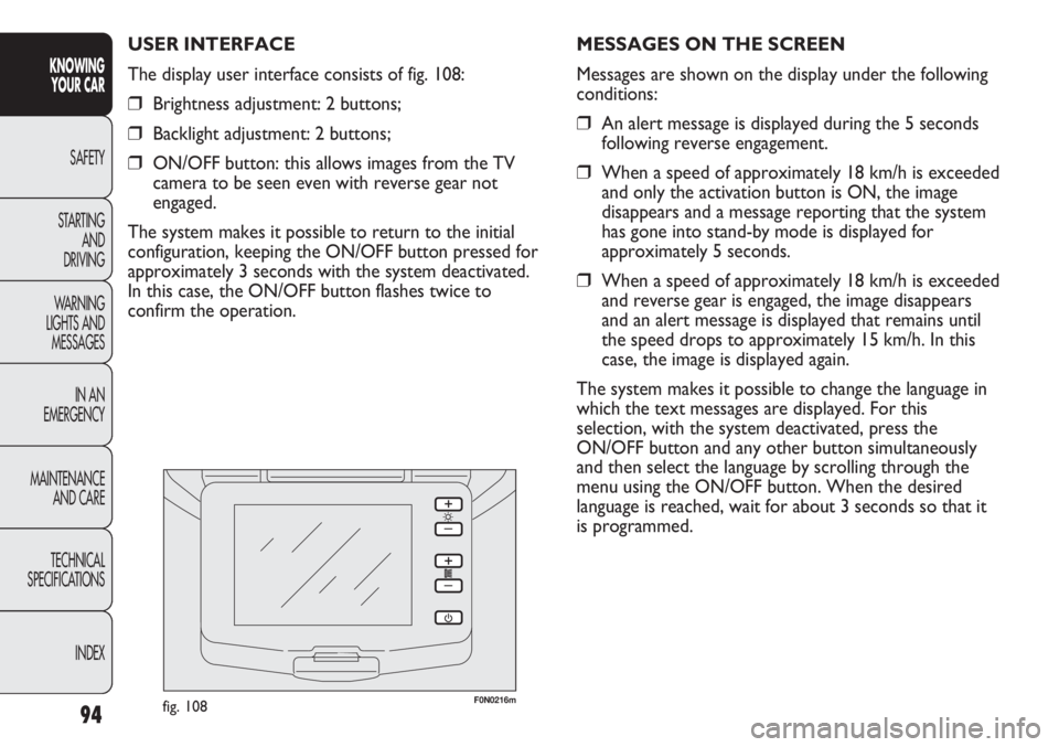
is programmed. USER INTERFACE
The display user interface consists of fig. 108:
❒Brightness adjustment: 2 buttons;
❒Backlight adjustment: 2 buttons;
❒ON/OFF button: this allows images from the TV
camera to be seen even with reverse gear not
engaged.
The system makes it possible to return to the initial
configuration, keeping the ON/OFF button pressed for
approximately 3 seconds with the system deactivated.
In this case, the ON/OFF button flashes twice to
confirm the operation.
Page 161 of 287
157
KNOWING
YOUR CAR
SAFETY
STARTING
AND
DRIVING
WARNING
LIGHTS AND
MESSAGES
IN AN
EMERGENCY
MAINTENANCE
AND CARE
TECHNICAL
SPECIFICATIONS
INDEX
WARNING LIGHTS AND MESSAGES
GENERAL WARNINGS
The turning on of the warning light is accompanied by
a specific message and/or buzzer sound where provided
by instrument panel. These indications are brief and
precautionary and as such must not be considered as
exhaustive and/or an alternative to the information
contained in the Owner Handbook, which you are
recommended to read carefully in all cases. Always refer
to the information in this chapter in the event of
a failure indication.
IMPORTANT Failure indications displayed are divided
into two categories: very serious and less serious
failures.
Very serious failures prompt a prolonged cycle of
signals.
Less serious failures prompt a shorter cycle of signals.
Press MODE to stop the warning cycle in both cases.
The instrument panel warning light will stay on until the
cause of the failure is eliminated.
For messages relevant to the versions equipped with
Dualogic gearbox, see the attached Supplement.
WARNING LIGHTS AND MESSAGES
If the warning light xturns on when
travelling (on certain versions together
with the message on the display) stop the car
immediately and contact a Fiat Dealership.
WARNING
LOW BRAKE FLUID LEVEL (red)
HANDBRAKE ENGAGED (red)
When the key is turned to the MAR-ON
position the warning light comes on but should
go out after a few seconds.
Low brake fluid level
The warning light comes on when the level of the brake
fluid in the reservoir falls below the minimum level due
to a possible leak in the circuit.
On some versions the display shows the dedicated
message.
x
Handbrake engaged
The warning light turns on when the handbrake is
engaged.
On certain versions, if the vehicle is moving the buzzer
will also sound.
IMPORTANT If the warning light turns on when
travelling, check that the handbrake is not engaged.
Page 165 of 287
161
KNOWING
YOUR CAR
SAFETY
STARTING
AND
DRIVING
WARNING
LIGHTS AND
MESSAGES
IN AN
EMERGENCY
MAINTENANCE
AND CARE
TECHNICAL
SPECIFICATIONS
INDEX
FRONT PASSENGER’S AIR BAG
DEACTIVATED (amber)
(for versions/markets, where provided)
The warning light
Fcomes on when the front
passenger’s air bag is deactivated.
With front passenger air bag on, when the ignition key
is turned to MAR-ON the
Fwarning light comes on
constantly for about 4 seconds and then should go out.
If the warning light
Fflashes to report a failure of the
warning light
¬, the passenger's protection is
deactivated for markets where this feature is available,
otherwise it it remains on.
INJECTION SYSTEM FAILURE
(amber)
In normal conditions, when the ignition key is
moved to MAR-ON, the warning light turns on
and should go off after engine start-up.
The warning light staying on or turning on when
travelling, signals a fault in the supply/ignition system
which could cause possible lack of performance, poor
handling and high consumption levels.
On some versions the display shows the dedicated
message.
Under these conditions, you may continue travelling at
moderate speed without demanding excessive effort
from the engine. Contact a Fiat Dealership as soon as
possible.
UF
Warning light Findicates failure of
warning light ¬. This condition is
indicated by intermittent blinking of warning
light
Ffor longer than 4 seconds. In this case,
the warning light ¬may not indicate failures in
the retaining system. Before resuming driving,
contact a Fiat Dealership immediately to have
the system checked.
WARNING
Page 174 of 287
170
KNOWING
YOUR CAR
SAFETY
STARTING
AND
DRIVING
WARNING
LIGHTS AND
MESSAGES
IN AN
EMERGENCY
MAINTENANCE
AND CARE
TECHNICAL
SPECIFICATIONS
INDEX
REPLACING A WHEEL
GENERAL INSTRUCTIONS
Wheel changing and correct use of the jack and spare
wheel (for versions/markets where provided) call for
some precautions, which are listed below. Proceed as follows to start the car:
❒raise the flap A to gain access to the positive battery
terminal fig. 157.
❒connect the positive terminals (+ sign near the
terminal) of the two batteries with a jump lead;
❒connect the negative terminal (–) of the auxiliary
battery to the earth point with a second cable as
shown in fig. 158;
❒Start the engine;
❒when the engine has been started, follow the
sequence above in reverse order to remove the
leads.
If after a few attempts the engine does not start, do not
persist but contact the nearest Fiat Dealership.
IMPORTANT Do not directly connect the negative
terminals of the two batteries: any sparks may ignite the
explosive gas which could come out of the battery.
If the auxiliary battery is installed on another vehicle,
prevent any metal parts on the latter and the vehicle
with the flat battery from accidentally coming into
contact.
BUMP STARTING
Never bump start the engine by pushing, towing or
driving downhill. This could cause a flow of fuel into the
catalytic converter and damage it beyond repair.
IMPORTANT Remember that the brake servo and the
power steering system are not activated until the engine
is started, a greater effort will therefore be required to
press the brake pedal or turn the steering wheel.Indicate that the vehicle is stationary
according to the regulations in force:
emergency lights, refracting warning triangle,
etc. Passengers should leave the vehicle,
particularly if it is very loaded, and wait for the
wheel to be changed away from on-coming
traffic. Apply the handbrake.
WARNING
The spare wheel (for versions/markets
where provided) is specific for your
vehicle. Therefore, it must not be used on
vehicles of a different model. Do not use spare
wheels of different models on your vehicle. The
wheel bolts are specific to your vehicle: do not
use them on other models and do not use bolts
of other models.
WARNING
Page 231 of 287
227
KNOWING
YOUR CAR
SAFETY
STARTING
AND
DRIVING
WARNING
LIGHTS AND
MESSAGES
IN AN
EMERGENCY
MAINTENANCE
AND CARE
TECHNICAL
SPECIFICATIONS
INDEX
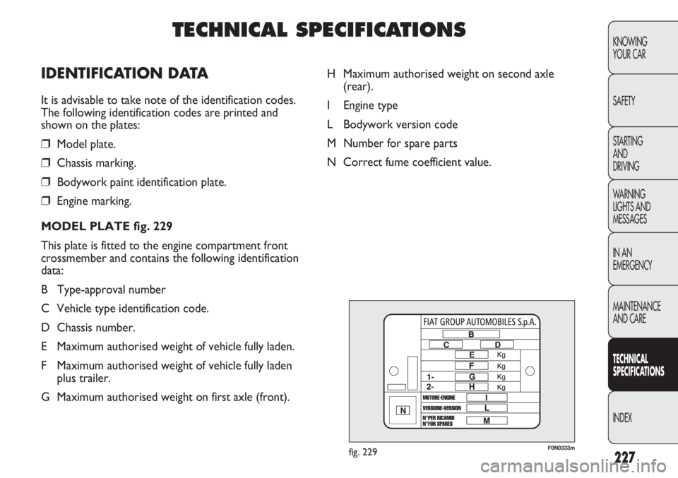
F0N0333mfig. 229
H Maximum authorised weight on second axle
(rear).
I Engine type
L Bodywork version code
M Number for spare parts
N Correct fume coefficient value.
TECHNICAL SPECIFICATIONS
IDENTIFICATION DATA
It is advisable to take note of the identification codes.
The following identification codes are printed and
shown on the plates:
❒Model plate.
❒Chassis marking.
❒Bodywork paint identification plate.
❒Engine marking.
MODEL PLATE fig. 229
This plate is fitted to the engine compartment front
crossmember and contains the following identification
data:
B Type-approval number
C Vehicle type identification code.
D Chassis number.
E Maximum authorised weight of vehicle fully laden.
F Maximum authorised weight of vehicle fully laden
plus trailer.
G Maximum authorised weight on first axle (front).