TRIM FIAT DUCATO 2011 Owner handbook (in English)
[x] Cancel search | Manufacturer: FIAT, Model Year: 2011, Model line: DUCATO, Model: FIAT DUCATO 2011Pages: 287, PDF Size: 4.42 MB
Page 151 of 287

147
KNOWING
YOUR CAR
SAFETY
STARTING
AND
DRIVING
WARNING
LIGHTS AND
MESSAGES
IN AN
EMERGENCY
MAINTENANCE
AND CARE
TECHNICAL
SPECIFICATIONS
INDEX
IMPORTANT For versions with right and left side flaps,
it is advisable to reposition the release lever in the
closed position before lowering the sides.
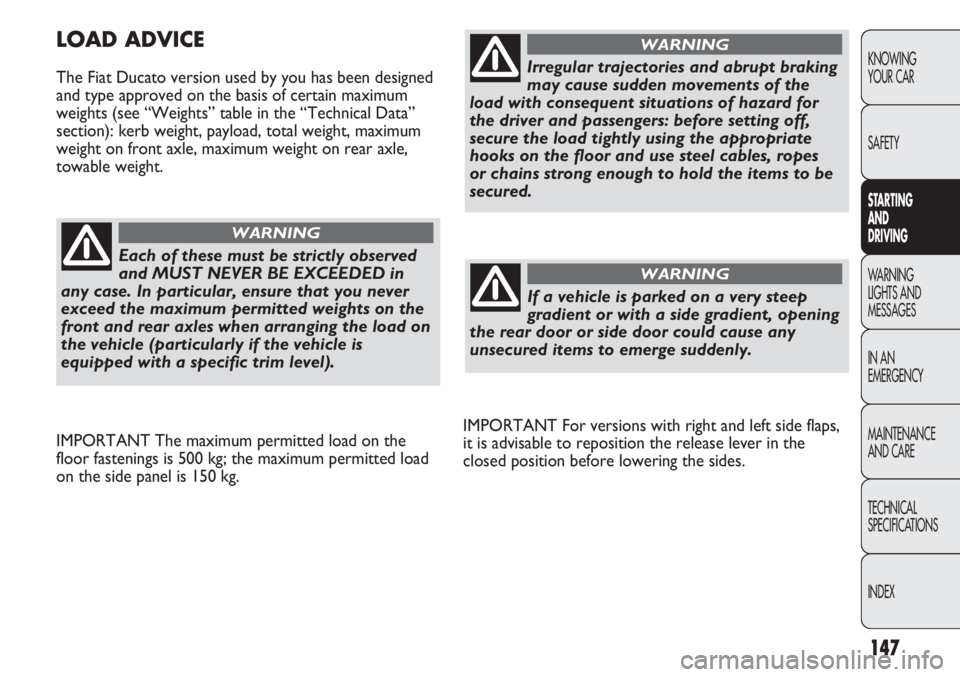
LOAD ADVICE
The Fiat Ducato version used by you has been designed
and type approved on the basis of certain maximum
weights (see “Weights” table in the “Technical Data”
section): kerb weight, payload, total weight, maximum
weight on front axle, maximum weight on rear axle,
towable weight.
Each of these must be strictly observed
and MUST NEVER BE EXCEEDED in
any case. In particular, ensure that you never
exceed the maximum permitted weights on the
front and rear axles when arranging the load on
the vehicle (particularly if the vehicle is
equipped with a specific trim level).
WARNING
IMPORTANT The maximum permitted load on the
floor fastenings is 500 kg; the maximum permitted load
on the side panel is 150 kg.
Irregular trajectories and abrupt braking
may cause sudden movements of the
load with consequent situations of hazard for
the driver and passengers: before setting off,
secure the load tightly using the appropriate
hooks on the floor and use steel cables, ropes
or chains strong enough to hold the items to be
secured.
WARNING
If a vehicle is parked on a very steep
gradient or with a side gradient, opening
the rear door or side door could cause any
unsecured items to emerge suddenly.
WARNING
Page 157 of 287

153
KNOWING
YOUR CAR
SAFETY
STARTING
AND
DRIVING
WARNING
LIGHTS AND
MESSAGES
IN AN
EMERGENCY
MAINTENANCE
AND CARE
TECHNICAL
SPECIFICATIONS
INDEX
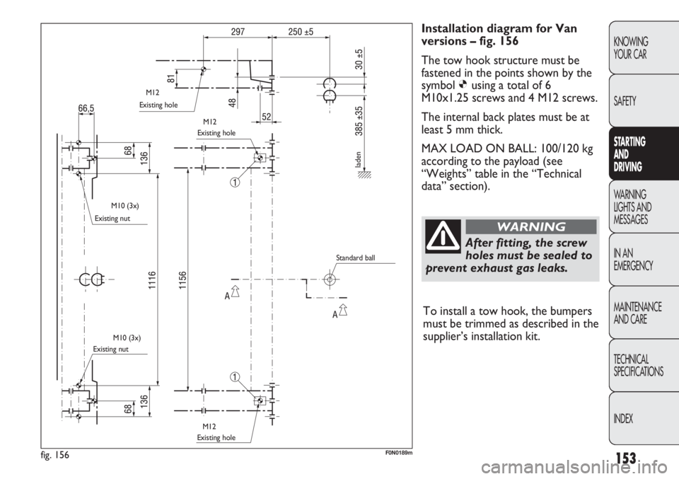
Installation diagram for Van
versions – fig. 156
The tow hook structure must be
fastened in the points shown by the
symbol Øusing a total of 6
M10x1.25 screws and 4 M12 screws.
The internal back plates must be at
least 5 mm thick.
MAX LOAD ON BALL: 100/120 kg
according to the payload (see
“Weights” table in the “Technical
data” section).
After fitting, the screw
holes must be sealed to
prevent exhaust gas leaks.
WARNING
fig. 156F0N0189m
Existing hole
Existing nut
Existing nutExisting hole
Existing hole
laden
Standard ball M12
M12
M10 (3x)
M10 (3x)
M12
To install a tow hook, the bumpers
must be trimmed as described in the
supplier’s installation kit.
Page 270 of 287

5.6
5.9
5.9
5.6
5.9
5.9
5.5
6.0
6.46.6
6.9
6.9
6.6
6.9
6.9
7.0
7.6
8.08.3
8.5
8.5
8.3
8.5
8.5
9.5
10.3
10.730q
33q
35q
30q
33q
35q
30q
33q
35q
6.1
6.1
6.47.1
7.1
8.08.7
8,7
10.7
266
KNOWING
YOUR CAR
SAFETY
STARTING
AND
DRIVING
WARNING
LIGHTS AND
MESSAGES
IN AN
EMERGENCY
MAINTENANCE
AND CARE
TECHNICAL
SPECIFICATIONS
INDEX
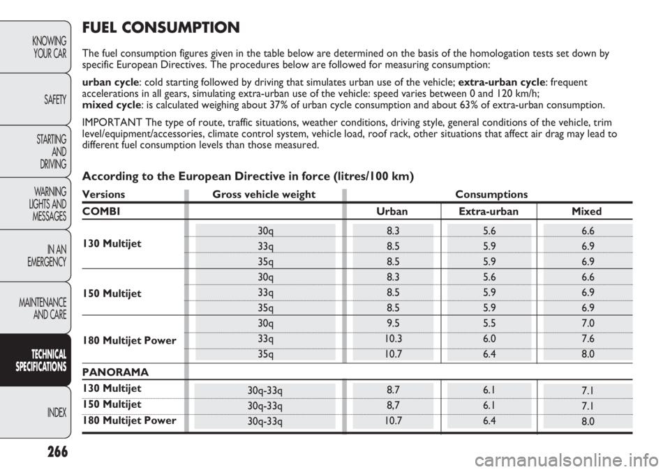
FUEL CONSUMPTION
The fuel consumption figures given in the table below are determined on the basis of the homologation tests set down by
specific European Directives. The procedures below are followed for measuring consumption:
urban cycle: cold starting followed by driving that simulates urban use of the vehicle; extra-urban cycle: frequent
accelerations in all gears, simulating extra-urban use of the vehicle: speed varies between 0 and 120 km/h;
mixed cycle: is calculated weighing about 37% of urban cycle consumption and about 63% of extra-urban consumption.
IMPORTANT The type of route, traffic situations, weather conditions, driving style, general conditions of the vehicle, trim
level/equipment/accessories, climate control system, vehicle load, roof rack, other situations that affect air drag may lead to
different fuel consumption levels than those measured.
130 Multijet
150 Multijet
180 Multijet Power
30q-33q
30q-33q
30q-33q
According to the European Directive in force (litres/100 km)
Versions Gross vehicle weight Consumptions
COMBI Urban Extra-urban Mixed
PANORAMA
130 Multijet
150 Multijet
180 Multijet Power