buttons FIAT DUCATO 2012 Owner handbook (in English)
[x] Cancel search | Manufacturer: FIAT, Model Year: 2012, Model line: DUCATO, Model: FIAT DUCATO 2012Pages: 287, PDF Size: 4.5 MB
Page 67 of 287
63
KNOWING
YOUR CAR
SAFETY
STARTING
AND
DRIVING
WARNING
LIGHTS AND
MESSAGES
IN AN
EMERGENCY
MAINTENANCE
AND CARE
TECHNICAL
SPECIFICATIONS
INDEX
F0N0151mfig. 56
To prioritise windscreen demisting, set the air
distribution knob to the
-position.
To obtain both functions, set the air distribution knob
to the
®position.
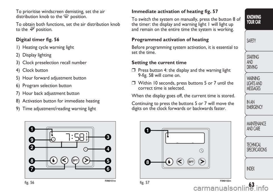
Digital timer fig. 56
1) Heating cycle warning light
2) Display lighting
3) Clock preselection recall number
4) Clock button
5) Hour forward adjustment button
6) Program selection button
7) Hour back adjustment button
8) Activation button for immediate heating
9) Time adjustment/reading warning light
F0N0152mfig. 57
Immediate activation of heating fig. 57
To switch the system on manually, press the button 8 of
the timer: the display and warning light 1 will light up
and remain on the entire time the system is working.
Programmed activation of heating
Before programming system activation, it is essential to
set the time.
Setting the current time
❒Press button 4: the display and the warning light
9-fig. 58 will come on.
❒Within 10 seconds, press buttons 5 or 7 until the
correct time is selected.
When the display goes off, the current time is stored.
Continuing to press the buttons 5 or 7 will move the
digits on the clock forwards or backwards faster.
Page 68 of 287
64
KNOWING
YOUR CAR
SAFETY
STARTING
AND
DRIVING
WARNING
LIGHTS AND
MESSAGES
IN AN
EMERGENCY
MAINTENANCE
AND CARE
TECHNICAL
SPECIFICATIONS
INDEX
F0N0153mfig. 58
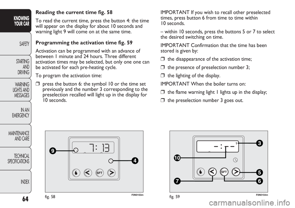
Reading the current time fig. 58
To read the current time, press the button 4: the time
will appear on the display for about 10 seconds and
warning light 9 will come on at the same time.
Programming the activation time fig. 59
Activation can be programmed with an advance of
between 1 minute and 24 hours. Three different
activation times may be selected, but only one one can
be activated for each pre-heating cycle.
To program the activation time:
❒press the button 6: the symbol 10 or the time set
previously and the number 3 corresponding to the
preselection recalled will light up in the display for
10 seconds.
F0N0154mfig. 59
IMPORTANT If you wish to recall other preselected
times, press button 6 from time to time within
10 seconds.
– within 10 seconds, press the buttons 5 or 7 to select
the desired switching on time.
IMPORTANT Confirmation that the time has been
stored is given by:
❒the disappearance of the activation time;
❒the presence of preselection number 3;
❒the lighting of the display.
IMPORTANT When the boiler turns on:
❒the flame warning light 1 lights up in the display;
❒the preselection number 3 goes out.
Page 95 of 287

91
KNOWING
YOUR CAR
SAFETY
STARTING
AND
DRIVING
WARNING
LIGHTS AND
MESSAGES
IN AN
EMERGENCY
MAINTENANCE
AND CARE
TECHNICAL
SPECIFICATIONS
INDEX
CAB GLOVE COMPARTMENT fig. 102
(for versions/markets where provided)
The storage compartment is fitted above the sun visors
and is designed for the quick storage of light objects
(e.g. documents, road maps etc.).
FLAP ON BENCH fig. 103
(for versions/markets where provided)
To use, the pull tab A and lower the flap.
The flap is equipped with two cup holders and a support
surface with a paper holder clip.
SATELLITE NAVIGATOR CAPABILITY fig. 104
(for versions/markets where provided)
This is located in the dashboard area illustrated in the
diagram for connecting the navigator.
F0N0191mfig. 102
F0N0149mfig. 103
F0N0512mfig. 104
Portable navigators to be fitted in the seat
in figure 104 have a mechanical release
device activated by pressing the two side
buttons on the stem. The failed operation of the
release may damage the seat of the navigator.
Page 96 of 287
92
KNOWING
YOUR CAR
SAFETY
STARTING
AND
DRIVING
WARNING
LIGHTS AND
MESSAGES
IN AN
EMERGENCY
MAINTENANCE
AND CARE
TECHNICAL
SPECIFICATIONS
INDEX
F0N0217mfig. 105F0N0214mfig. 106
The rear view display is adjusted in mirror mode. When
not in use, it must be closed in the upper oddments
compartment console area.
ACTIVATION
The system is activated with the ignition on and reverse
engaged or by means of a dedicated button. If the
vehicle is in motion, e.g. during a reversing manoeuvre,
the system will operate up to a speed of 15 km/h and go
off when a speed of approximately 18 km/h is exceeded.
When reverse is deactivated, the image will appear on
the display for a further 5 seconds. TV CAMERA SYSTEM
AND REAR VISIBILITY DISPLAY
(for versions/markets where provided)
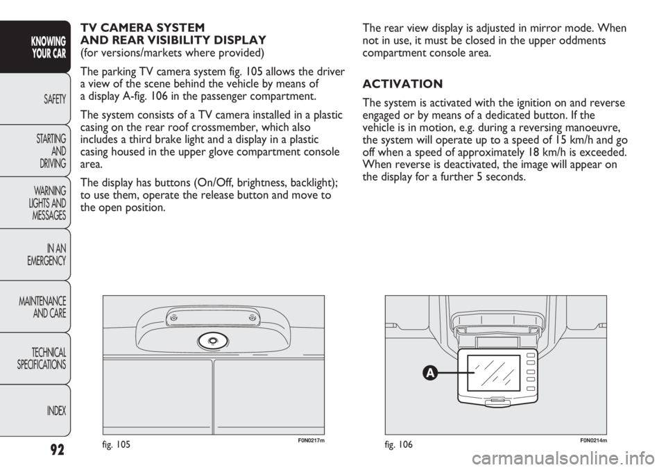
The parking TV camera system fig. 105 allows the driver
a view of the scene behind the vehicle by means of
a display A-fig. 106 in the passenger compartment.
The system consists of a TV camera installed in a plastic
casing on the rear roof crossmember, which also
includes a third brake light and a display in a plastic
casing housed in the upper glove compartment console
area.
The display has buttons (On/Off, brightness, backlight);
to use them, operate the release button and move to
the open position.
Page 98 of 287
94
KNOWING
YOUR CAR
SAFETY
STARTING
AND
DRIVING
WARNING
LIGHTS AND
MESSAGES
IN AN
EMERGENCY
MAINTENANCE
AND CARE
TECHNICAL
SPECIFICATIONS
INDEX
F0N0216mfig. 108
MESSAGES ON THE SCREEN
Messages are shown on the display under the following
conditions:
❒An alert message is displayed during the 5 seconds
following reverse engagement.
❒When a speed of approximately 18 km/h is exceeded
and only the activation button is ON, the image
disappears and a message reporting that the system
has gone into stand-by mode is displayed for
approximately 5 seconds.
❒When a speed of approximately 18 km/h is exceeded
and reverse gear is engaged, the image disappears
and an alert message is displayed that remains until
the speed drops to approximately 15 km/h. In this
case, the image is displayed again.
The system makes it possible to change the language in
which the text messages are displayed. For this
selection, with the system deactivated, press the
ON/OFF button and any other button simultaneously
and then select the language by scrolling through the
menu using the ON/OFF button. When the desired
language is reached, wait for about 3 seconds so that it
is programmed. USER INTERFACE
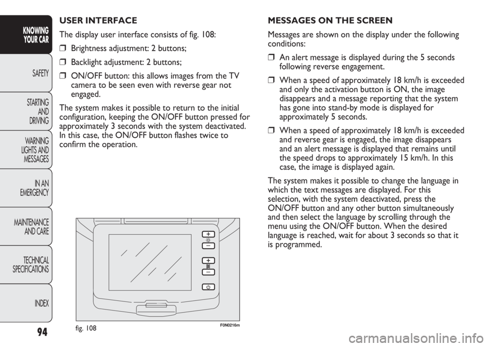
The display user interface consists of fig. 108:
❒Brightness adjustment: 2 buttons;
❒Backlight adjustment: 2 buttons;
❒ON/OFF button: this allows images from the TV
camera to be seen even with reverse gear not
engaged.
The system makes it possible to return to the initial
configuration, keeping the ON/OFF button pressed for
approximately 3 seconds with the system deactivated.
In this case, the ON/OFF button flashes twice to
confirm the operation.
Page 100 of 287
96
KNOWING
YOUR CAR
SAFETY
STARTING
AND
DRIVING
WARNING
LIGHTS AND
MESSAGES
IN AN
EMERGENCY
MAINTENANCE
AND CARE
TECHNICAL
SPECIFICATIONS
INDEX
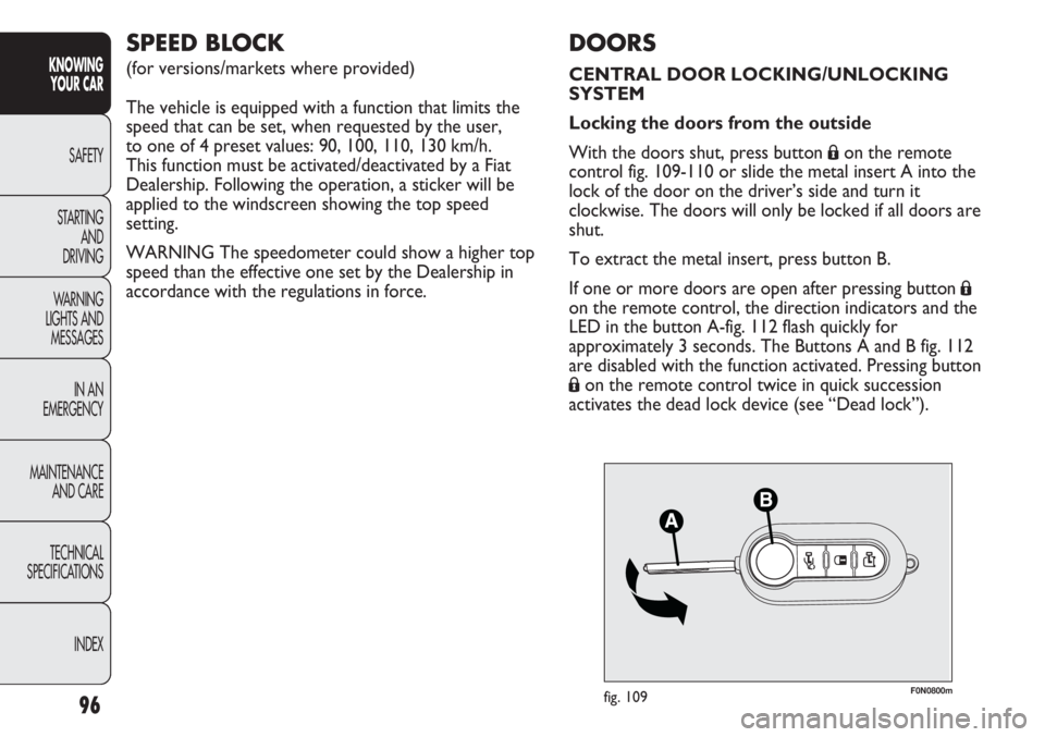
F0N0800mfig. 109
DOORS
CENTRAL DOOR LOCKING/UNLOCKING
SYSTEM
Locking the doors from the outside
With the doors shut, press button
Áon the remote
control fig. 109-110 or slide the metal insert A into the
lock of the door on the driver’s side and turn it
clockwise. The doors will only be locked if all doors are
shut.
To extract the metal insert, press button B.
If one or more doors are open after pressing button
Á
on the remote control, the direction indicators and the
LED in the button A-fig. 112 flash quickly for
approximately 3 seconds. The Buttons A and B fig. 112
are disabled with the function activated. Pressing button
Áon the remote control twice in quick succession
activates the dead lock device (see “Dead lock”).
SPEED BLOCK
(for versions/markets where provided)
The vehicle is equipped with a function that limits the
speed that can be set, when requested by the user,
to one of 4 preset values: 90, 100, 110, 130 km/h.
This function must be activated/deactivated by a Fiat
Dealership. Following the operation, a sticker will be
applied to the windscreen showing the top speed
setting.
WARNING The speedometer could show a higher top
speed than the effective one set by the Dealership in
accordance with the regulations in force.
Page 103 of 287
99
KNOWING
YOUR CAR
SAFETY
STARTING
AND
DRIVING
WARNING
LIGHTS AND
MESSAGES
IN AN
EMERGENCY
MAINTENANCE
AND CARE
TECHNICAL
SPECIFICATIONS
INDEX
The LED comes on in the following cases:
❒after each door lock command generated by the
button D or by button
Áin the dashboard;
❒when the instrument panel is activated;
❒upon opening of one of the front doors;
❒when the door is locked at 20 km/h (if activated
from the menu).
The lock is turned off when one of the load
compartment doors is opened or on a door release
request (load compartment or centralised) or an
unlocking request from the remote control/door catch.
DEAD LOCK
(for versions/markets where provided)
This safety device inhibits the operation of:
❒interior handles;
❒locking/unlocking buttons A-B fig. 112;
thereby preventing the opening of the doors from inside
the passenger compartment if there has been a break-in
attempt (e.g. a window has been broken).
The dead lock device therefore offers the best possible
protection against break in attempts. We recommend
engaging it whenever the vehicle is parked and left
unattended.
Once the dead lock system is engaged it
is impossible to open the doors from
inside the vehicle. Therefore, before engaging
the system check that there is no one left inside.
If the remote control battery is flat, the system
can only be disengaged by using the metal insert
in either of the door locks as described
previously: in this case the device only remains
on for the rear doors.
WARNING
Device activation
The dead lock device is automatically activated on every
door when pressing the remote control button
Ábriefly
twice, fig. 109.
Device activation is indicated by 3 flashes of the
direction indicators and the flashing of the LED on
button A-fig. 112 on the dashboard.
If one of the doors is not perfectly shut, the dead lock
device will not be activated, thus preventing a person
getting into the car through the open door and, on
shutting it, remaining stuck inside the passenger
compartment.
Page 107 of 287
103
KNOWING
YOUR CAR
SAFETY
STARTING
AND
DRIVING
WARNING
LIGHTS AND
MESSAGES
IN AN
EMERGENCY
MAINTENANCE
AND CARE
TECHNICAL
SPECIFICATIONS
INDEX
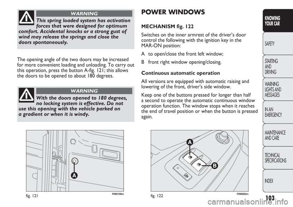
F0N0188mfig. 121F0N0062mfig. 122
POWER WINDOWS
MECHANISM fig. 122
Switches on the inner armrest of the driver’s door
control the following with the ignition key in the
MAR-ON position:
A to open/close the front left window;
B front right window opening/closing.
Continuous automatic operation
All versions are equipped with automatic raising and
lowering of the front, driver’s side window.
Keep one of the buttons pressed for longer than half
a second to operate the automatic continuous window
operation function. The window stops when it reaches
the end of travel position or when the button is pressed
again. The opening angle of the two doors may be increased
for more convenient loading and unloading. To carry out
this operation, press the button A-fig. 121; this allows
the doors to be opened to about 180 degrees.
This spring loaded system has activation
forces that were designed for optimum
comfort. Accidental knocks or a strong gust of
wind may release the springs and close the
doors spontaneously.
WARNING
With the doors opened to 180 degrees,
no locking system is effective. Do not
use this opening with the vehicle parked on
a gradient or when it is windy.
WARNING
Page 112 of 287
108
KNOWING
YOUR CAR
SAFETY
STARTING
AND
DRIVING
WARNING
LIGHTS AND
MESSAGES
IN AN
EMERGENCY
MAINTENANCE
AND CARE
TECHNICAL
SPECIFICATIONS
INDEX
ABS SYSTEM
If you have never driven a vehicle with ABS before, it is
advisable to perform a few tests on slippery ground,
always in safe conditions and respecting the highway
code of the country where you are driving. Read the
following information carefully.
This is an integral part of the braking system, which
prevents one or more wheels from locking or slipping
regardless of the road surface conditions and braking
intensity, ensuring control of the vehicle even during
emergency braking.
The system is completed by EBD (Electronic Braking
Force Distribution), which distributes the braking action
between the front and rear wheels.
IMPORTANT For the maximum efficiency of the
braking system, a bedding in period of about 500 km is
needed (with the vehicle new or after having replaced
the brake pads/discs): during this period it is better to
avoid sharp, repeated and prolonged braking. Headlight alignment adjustment fig. 128
Press buttons Òand in the control panel to adjust.
The display located on the instrument panel provides
a visual indication of the adjusted position.
IMPORTANT Check the beam alignment every time the
weight of the load transported changes.
FRONT FOG LIGHTS ALIGNMENT
(for versions/markets where provided)
Contact a Fiat Dealership to have the headlights
properly adjusted.
ADJUSTING THE HEADLIGHTS WHEN
ABROAD
The dipped headlights are adjusted to work in the
country where the vehicle was originally purchased.
In countries where vehicles are driven on the other side
of the road, the beams are aligned by applying a specially
designed adhesive film in order not to dazzle the
vehicles travelling in the opposite direction.
The ABS system gets the most out of the
available grip but it cannot improve it.
Therefore, you should take great care when
driving on slippery surfaces: don’t take
unnecessary risks.
WARNING