High FIAT DUCATO 2014 3.G User Guide
[x] Cancel search | Manufacturer: FIAT, Model Year: 2014, Model line: DUCATO, Model: FIAT DUCATO 2014 3.GPages: 367, PDF Size: 20.39 MB
Page 59 of 367
Warning lights
and
are lit up in the
instrument panel when this device is
activated. Press switch A again to turn
the lights off.
IMPORTANT The use of hazard warning
lights is governed by the highway
code of the country you are in. Comply
with legal requirements.
Emergency braking
(for versions/markets, where provided)
In the event of emergency braking
the hazard warning lights come on
automatically, as do theand
warning lights in the panel. The
function switches off automatically
when the nature of the braking
changes. This function complies with
the relevant legislation currently in force.
FOG LIGHTS
(for versions/markets, where provided)
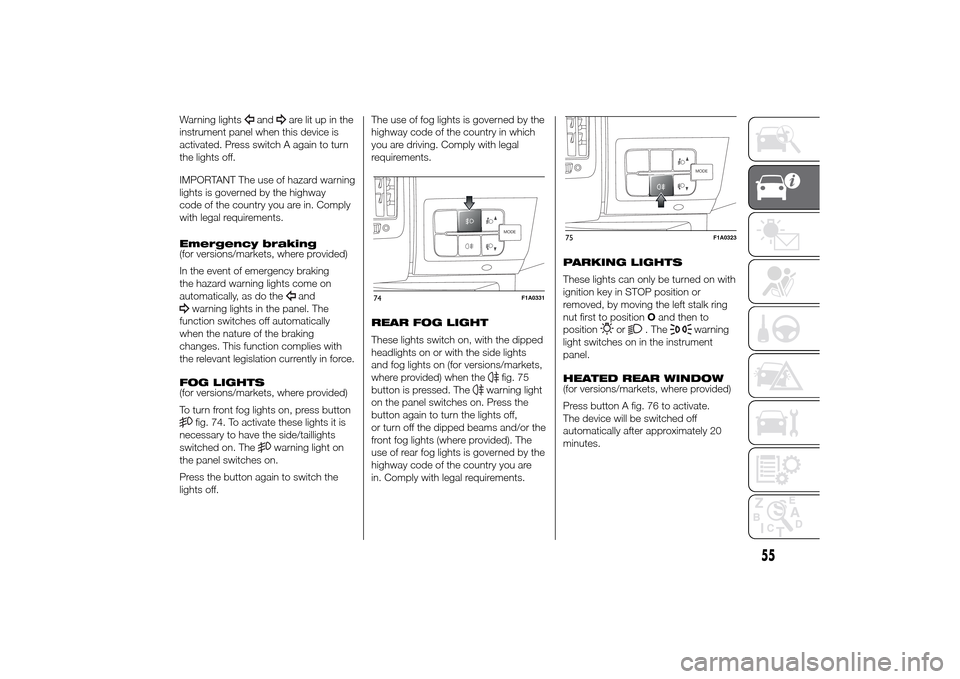
To turn front fog lights on, press buttonfig. 74. To activate these lights it is
necessary to have the side/taillights
switched on. The
warning light on
the panel switches on.
Press the button again to switch the
lights off.The use of fog lights is governed by the
highway code of the country in which
you are driving. Comply with legal
requirements.
REAR FOG LIGHT
These lights switch on, with the dipped
headlights on or with the side lights
and fog lights on (for versions/markets,
where provided) when the
fig. 75
button is pressed. The
warning light
on the panel switches on. Press the
button again to turn the lights off,
or turn off the dipped beams and/or the
front fog lights (where provided). The
use of rear fog lights is governed by the
highway code of the country you are
in. Comply with legal requirements.PARKING LIGHTS
These lights can only be turned on with
ignition key in STOP position or
removed, by moving the left stalk ring
nut first to positionOand then to
position
or
. The
warning
light switches on in the instrument
panel.
HEATED REAR WINDOW
(for versions/markets, where provided)
Press button A fig. 76 to activate.
The device will be switched off
automatically after approximately 20
minutes.
MODE
74
F1A0331
MODE
75
F1A0323
55
Page 66 of 367

❒fit the tablet between the locking
devices B;
❒lift the lever A to ensure that the
device is locked.
33)
SHELF ABOVE THE CAB
(for versions/markets, where provided)
This is located above the driver's cab
fig. 100 and is designed to store light
objects.
Maximum permitted load:
– localised: 10 kg
– distributed over the entire surface of
the shelf: 20 kgCAB GLOVE
COMPARTMENT
(CAPUCINE)
(for versions/markets, where provided)
The storage compartment is fitted
above the sun visors fig. 101 and is
designed for the quick storage of light
objects (e.g. documents, road maps
etc.).FLAP ON BENCH
(for versions/markets, where provided)
To use, pull tab A fig. 102 and lower the
flap. The flap is equipped with two
cup holder indents and a support
surface with a paper holder clip.
WARNING
31) The cigar lighter reaches high
temperatures. Handle it carefully
and make sure that children don't
touch it: risk of fire and/or
burning.
32) Do not use the desk in a vertical
position with the vehicle in
motion.
99
F1A0342
100
F1A0103
101
F1A0104
102
F1A0105
62
KNOW YOUR VEHICLE
Page 68 of 367
SPEED BLOCK(for versions/markets, where provided)
The vehicle is equipped with a speed
limitation function that can be set at the
user's request to one of 4 predefined
values: 90, 100, 110, 130 km/h.
To activate/deactivate this function,
contact a Fiat Dealership.
Following the operation, a sticker will be
applied to the windscreen showing the
maximum speed setting.
IMPORTANT The speedometer could
indicate a higher maximum speed than
the effective one, set by the Dealership,
in accordance with the regulations in
force.
SELF-LEVELLING AIR
SUSPENSIONGENERAL INFORMATION
The system only acts on the rear
wheels.
The system maintains the rear ride
setting for the vehicle constant in any
loading condition, while ensuring a
greater driving comfort. In addition, the
system allows the height of the vehicle
to be adjusted with the vehicle
stationary, by selecting from 7 different
positions to facilitate access to the
rear compartment.
HEIGHT ADJUSTMENT
There are 7 pre-defined levels for the
free height from the ground: from “ride
-3” to “ride 0” till “ride +3”.
The multifunction display, located in the
middle of the instrument panel, can
show the ride position.
Automatic adjustment
When moving, the system automatically
shows that the vehicle is in 'ride setting
0' and keeps it constant.
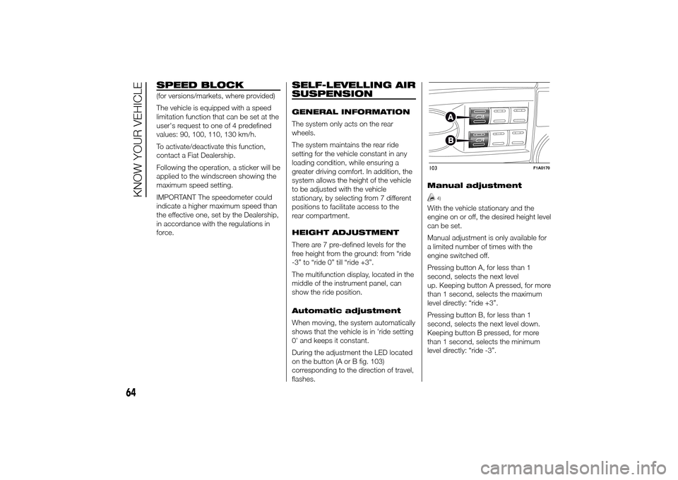
During the adjustment the LED located
on the button (A or B fig. 103)
corresponding to the direction of travel,
flashes.Manual adjustment
4)
With the vehicle stationary and the
engine on or off, the desired height level
can be set.
Manual adjustment is only available for
a limited number of times with the
engine switched off.
Pressing button A, for less than 1
second, selects the next level
up. Keeping button A pressed, for more
than 1 second, selects the maximum
level directly: “ride +3”.
Pressing button B, for less than 1
second, selects the next level down.
Keeping button B pressed, for more
than 1 second, selects the minimum
level directly: “ride -3”.103
F1A0170
64
KNOW YOUR VEHICLE
Page 80 of 367
❒ASR
❒HBA
❒DST
❒ERM
54) 55) 56)
SYSTEM INTERVENTION
This is signalled by the flashing of
warning light
in the instrument panel,
to inform the driver that the vehicle is
in critical stability and grip conditions.
SYSTEM ACTIVATION
The ESC system switches on
automatically when the engine is
started and cannot be switched off.
HILL HOLDER SYSTEM
This system is an integral part of the
ESC system and facilitates starting on
slopes.
It is automatically activated in the
following conditions:
❒uphill: vehicle stationary on a road
with a gradient higher than 5%,
engine running, brake pressed and
gearbox in neutral or gear (other than
reverse) engaged;❒downhill: vehicle stationary on a road
with a gradient higher than 5%,
engine running, brake pressed and
reverse gear engaged.
When setting off, the ESC system
control unit maintains the braking
pressure on the wheels until the torque
necessary for starting is reached, or
in any case for a maximum of 2
seconds, allowing your right foot to be
moved easily from the brake pedal to
the accelerator.
When two seconds have elapsed,
without starting, the system is
automatically deactivated, gradually
releasing the braking pressure. During
this release stage, the typical brake
disengagement noise indicating that the
vehicle is going to move imminently
will be heard.
IMPORTANT The Hill Holder system is
not a parking brake; therefore, never
leave the vehicle without having
engaged the handbrake, turned the
engine off and engaged first gear,
so that it is parked in safe conditions
(for further information read the
"Parking" paragraph in the "Starting
and driving" chapter).ASR (AntiSlip
Regulation) SYSTEM
It is an integral part of the ESC system.
It automatically operates in the event
of one or both drive wheels slipping,
loss of grip on wet roads (aquaplaning)
and acceleration on slippery, snowy
or icy roads, etc.
Depending on the slipping conditions,
two different control systems are
activated:
❒if the slipping involves both drive
wheels, the ASR intervenes reducing
the power transmitted by the engine;
❒if the slipping only involves one of the
drive wheels, it intervenes
automatically braking the wheel that
is slipping.
58)
Engagement/ disengagement of the
ASR system
The ASR system switches on
automatically each time the engine is
started.
Whilst driving, the ASR can be switched
off and subsequently switched on
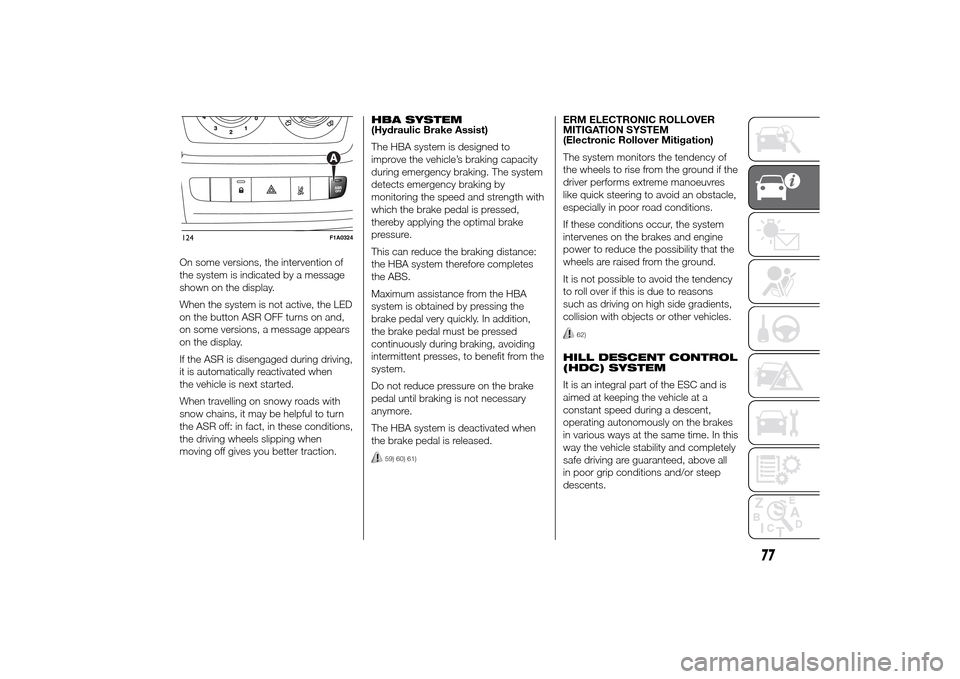
again by pressing the ASR OFF button
fig. 124.
57)
76
KNOW YOUR VEHICLE
Page 81 of 367
On some versions, the intervention of
the system is indicated by a message
shown on the display.
When the system is not active, the LED
on the button ASR OFF turns on and,
on some versions, a message appears
on the display.
If the ASR is disengaged during driving,
it is automatically reactivated when
the vehicle is next started.
When travelling on snowy roads with
snow chains, it may be helpful to turn
the ASR off: in fact, in these conditions,
the driving wheels slipping when
moving off gives you better traction.HBA SYSTEM
(Hydraulic Brake Assist)
The HBA system is designed to
improve the vehicle’s braking capacity
during emergency braking. The system
detects emergency braking by
monitoring the speed and strength with
which the brake pedal is pressed,
thereby applying the optimal brake
pressure.
This can reduce the braking distance:
the HBA system therefore completes
the ABS.
Maximum assistance from the HBA
system is obtained by pressing the
brake pedal very quickly. In addition,
the brake pedal must be pressed
continuously during braking, avoiding
intermittent presses, to benefit from the
system.
Do not reduce pressure on the brake
pedal until braking is not necessary
anymore.
The HBA system is deactivated when
the brake pedal is released.
59) 60) 61)
ERM ELECTRONIC ROLLOVER
MITIGATION SYSTEM
(Electronic Rollover Mitigation)
The system monitors the tendency of
the wheels to rise from the ground if the
driver performs extreme manoeuvres
like quick steering to avoid an obstacle,
especially in poor road conditions.
If these conditions occur, the system
intervenes on the brakes and engine
power to reduce the possibility that the
wheels are raised from the ground.
It is not possible to avoid the tendency
to roll over if this is due to reasons
such as driving on high side gradients,
collision with objects or other vehicles.
62)
HILL DESCENT CONTROL
(HDC) SYSTEM
It is an integral part of the ESC and is
aimed at keeping the vehicle at a
constant speed during a descent,
operating autonomously on the brakes
in various ways at the same time. In this
way the vehicle stability and completely
safe driving are guaranteed, above all
in poor grip conditions and/or steep
descents.
124
F1A0324
77
Page 85 of 367
The tyre pressure also increases while
driving the vehicle: this is a normal
condition and does not require any
adjustment of the pressure.
The TPMS continues to advise the
driver of the low tyre pressure condition
until this is corrected; the warning
continues until the pressure
corresponds or exceeds the pressure
prescribed for the cold tyres. When the
tyre low pressure control warning
light
switches on constantly, the
inflation pressure must be adjusted until
it reaches the pressure prescribed for
cold tyres. After the automatic update
of the system, the tyre pressure control
warning light switches off. You may
need to drive the vehicle for about 20
minutes at a speed higher than 20
km/h to allow the TPMS to receive this
information.
NOTE
❒The TPMS does not replace the
normal tyre maintenance service and
does not indicate any fault in a tyre.
❒Therefore, the TPMS should not be
used as pressure switch while
adjusting the tyre inflation pressure.❒Driving with insufficient tyre pressure
causes their overheating and can
result in tyre failure. The low inflation
pressure reduces fuel efficiency
and tyre tread life and may also affect
handling and braking performance
of the vehicle.
❒The TPMS does not replace the
correct tyre maintenance. It is up to
the driver to maintain the correct tyre
pressure level measuring it with a
suitable pressure switch. This is
necessary even if the decrease in the
inflation pressure value does not
cause the tyre pressure control
warning light to switch on.
❒The TPMS warns the driver of any
condition of insufficient tyre pressure
If this drops below the insufficient
pressure limit for any reason including
low temperature and normal
pressure loss of the tyre.
❒The seasonal temperature changes
affect tyre pressure.
The TPMS uses wireless devices with
electronic sensors mounted on the
wheel rims to constantly monitor the
value of tyre pressure. The sensors
mounted on each wheel as part of the
valve stem transmit various information
of the tyres to the receiver module, in
order to calculate the pressure.WARNING Monitoring and maintaining
the correct pressure in all four tyres
are particularly important.
Tyre pressure
monitoring system low
pressure warnings
The system warns the driver if one or
more tyres are flat by switching on
the warning light
on the instrument
panel (together with a warning message
and an acoustic signal).
In this case, stop the vehicle as soon as
possible, check the inflation pressure
of each tyre and inflate to the cold tyre
pressure value prescribed for the
vehicle. The system will automatically
update and after receiving the tyre
pressure update the tyre pressure
control warning light switches off. You
may need to drive the vehicle for about
20 minutes at a speed higher than 20
km/h to allow the system to receive this
information.
TPMS operation faults
The system fault is indicated by
warning light
which first flashes for
75 seconds and then stays on steadily.
This can occur in any of the following
situations:
81
Page 86 of 367
❒interference caused by electronic
devices or radio frequency emissions
similar to those of the TPM sensors.
❒Application of tinted films which
interfere with the signals of the radio
waves.
❒Presence of snow or ice on the
wheels or the wheel arches.
❒Use of snow chains.
❒Use of wheels/tyres not equipped
with TPM sensors.
❒The space-saver wheel is not
equipped with the tyre pressure
control sensor. Therefore, the tyre
pressure is not controlled by the
system.
❒If the space-saver wheel replaces a
tyre with a pressure lower than the
insufficient pressure limit, an acoustic
signal will be emitted and the warning
light
will switch on at the next
ignition cycle.❒When the original tyre is repaired or
replaced and it is mounted back on
the vehicle to replace the space-
saver wheel, the TPMS will update
automatically and the warning light
will switch off, provided that the
pressure of none of the four tyres is
below the insufficient pressure limit.
You may need to drive the vehicle for
about 20 minutes at a speed higher
than 20 km/h to allow the TPMS
to receive this information.IMPORTANT
INFORMATION
WARNING
65) The TPMS is optimised for the
original tyres and wheels
provided. TPMS pressures and
alerts have been defined
according to the size of the tyres
mounted on the vehicle. Using
equipment with different size,
type or kind may cause irregular
system operation or sensor
damage. Non-original spare
wheels can damage the sensor.
Do not use tyre sealant or
balancing weights if the vehicle is
equipped with TPMS as these
may damage the sensors.
66) If the system signals a pressure
decrease on a specific tyre, it is
recommended to check the
pressure on all four tyres.
67) TPMS does not relieve the driver
from the obligation to check the
tyre pressure every month; it is
not even to be considered a
replacing system for maintenance
or a safety system.
82
KNOW YOUR VEHICLE
Page 87 of 367
68) Tyre pressure must be checked
with tyres cold. Should it become
necessary for whatever reason
to check pressure with warm
tyres, do not reduce pressure
even if it is higher than the
prescribed value, but repeat the
check when tyres are cold.
69) The TPMS cannot indicate
sudden tyre pressure drops (for
example when a tyre bursts).
In this case, stop the car, braking
with caution and avoiding abrupt
steering.
70) The system only warns that the
tyre pressure is low: it is not able
to inflate them.
71) An insufficient tyre inflation
increases fuel consumption,
reduces the tread duration and
may affect the capacity of driving
safely.
72) Always refit the valve stem cap
after inspecting or adjusting tyre
pressure. This prevents dampness
or dirt from entering the valve
stem and thus the pressure
control sensor from being
damaged.73) The tyre repair kit (Fix&Go)
provided with the car (for
versions/markets, where
provided) is compatible with the
TPMS sensors; using sealants not
equivalent with that in the original
kit may adversely affect its
operation. If sealants not
equivalent with the original one
are used, it is recommended to
have the TPMS sensor operation
checked by a qualified repair
centre.
DRIVING ADVISOR(lane crossing warning)
(for versions/markets, where provided)
78) 75) 76)
The Driving Advisor is a warning system
that notifies the driver if he/she crosses
the lane because he/she has been
distracted.
A video sensor, fitted on the windscreen
near the interior rear view mirror,
detects the lane demarcation lines and
the position of the car in relation to
them.
IMPORTANT On cars with Driving
Advisor, it is advisable to contact a Fiat
Dealership should the windscreen
need to be replaced. If the repair is
carried out at a specialist window
replacement centre, it is still necessary
to go to a Fiat Dealership to have the
camera calibrated.
OPERATION
The system is always active when the
vehicle is started. It can be deactivated
or re-activated by pressing button A
fig. 127 on the dashboard (see
following description).
83
Page 94 of 367
IMPORTANT When parking, take the
utmost care over obstacles that may be
above or under the camera range.
WARNING
77) The responsibility for parking
and other manoeuvres is always
and in any case charged to the
driver. While carrying out these
manoeuvres, always make sure
that no people (especially
children) or animals are in the
area concerned. The camera is an
aid for the driver, but the driver
must never allow his/her attention
to lapse during potentially
dangerous manoeuvres, even
those executed at low speeds.
Always keep a slow speed, so as
to promptly brake in the case
of obstacles.
IMPORTANT
8) It is vital, for correct operation,
that the camera is always kept
clean and free from mud, dirt,
snow or ice. Be careful not to
scratch or damage the camera
while cleaning it. Avoid using dry,
rough or hard cloths. The camera
must be washed using clean
water, with the addition of car
shampoo if necessary. In washing
stations which use steam or
high-pressure jets, clean the
camera quickly, keeping the
nozzle more than 10 cm away
from the sensors. Do not apply
stickers to the camera.
TRAFFIC SIGN
RECOGNITION(for versions/markets, where provided)
74) 79) 80) 81)9) 10) 11) 12) 13) 14) 15)
The system automatically detects the
recognisable traffic signs: speed limits,
no overtaking signs and signs indicating
the end of such prohibitions.
The camera is fitted behind the internal
rear view mirror. The sensor always
checks the traffic signs indicating the
current speed limit and possible no
overtaking signs.
IMPORTANT The system is designed to
read signs complying with the
specifications of the Vienna convention.
USE OF THE TRAFFIC
SIGN RECOGNITION
System switching on
and off
The system can be activated/
deactivated using the display menu.
Refer to the "Display" paragraph in the
"Knowing the instrument panel"
chapter.
Note: the system condition and settings
do not change throughout the different
on-off cycles.
90
KNOW YOUR VEHICLE
Page 97 of 367
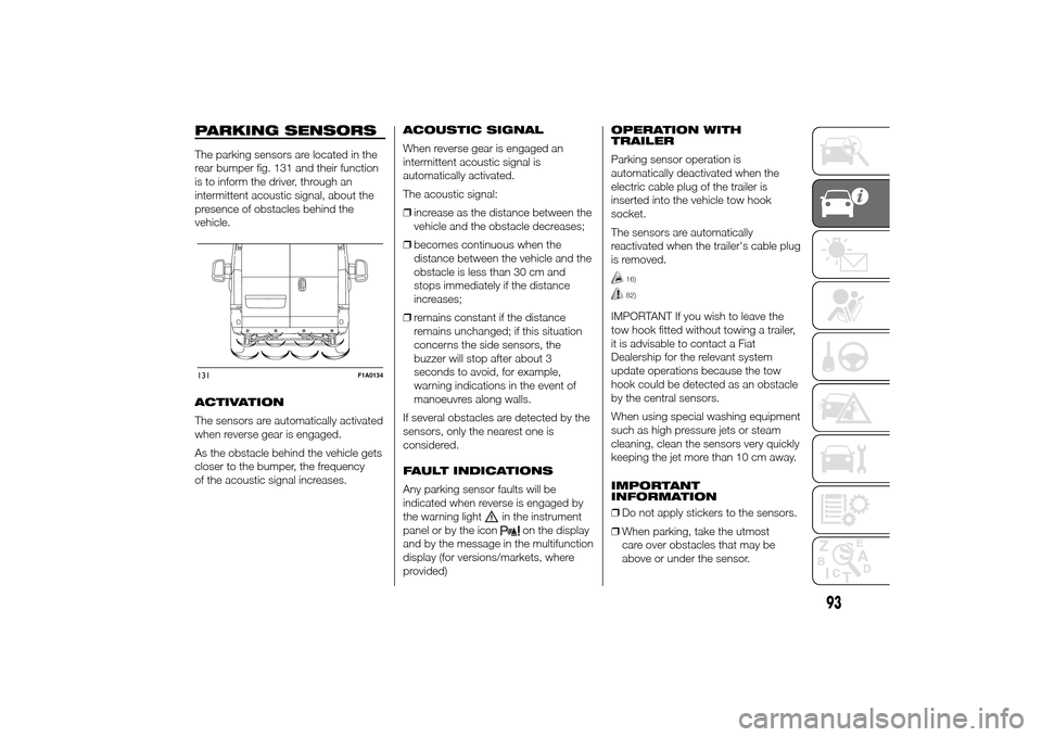
PARKING SENSORSThe parking sensors are located in the
rear bumper fig. 131 and their function
is to inform the driver, through an
intermittent acoustic signal, about the
presence of obstacles behind the
vehicle.
ACTIVATION
The sensors are automatically activated
when reverse gear is engaged.
As the obstacle behind the vehicle gets
closer to the bumper, the frequency
of the acoustic signal increases.ACOUSTIC SIGNAL
When reverse gear is engaged an
intermittent acoustic signal is
automatically activated.
The acoustic signal:
❒increase as the distance between the
vehicle and the obstacle decreases;
❒becomes continuous when the
distance between the vehicle and the
obstacle is less than 30 cm and
stops immediately if the distance
increases;
❒remains constant if the distance
remains unchanged; if this situation
concerns the side sensors, the
buzzer will stop after about 3
seconds to avoid, for example,
warning indications in the event of
manoeuvres along walls.
If several obstacles are detected by the
sensors, only the nearest one is
considered.
FAULT INDICATIONS
Any parking sensor faults will be
indicated when reverse is engaged by
the warning light
in the instrument
panel or by the icon
on the display
and by the message in the multifunction
display (for versions/markets, where
provided)OPERATION WITH
TRAILER
Parking sensor operation is
automatically deactivated when the
electric cable plug of the trailer is
inserted into the vehicle tow hook
socket.
The sensors are automatically
reactivated when the trailer's cable plug
is removed.
16)82)
IMPORTANT If you wish to leave the
tow hook fitted without towing a trailer,
it is advisable to contact a Fiat
Dealership for the relevant system
update operations because the tow
hook could be detected as an obstacle
by the central sensors.
When using special washing equipment
such as high pressure jets or steam
cleaning, clean the sensors very quickly
keeping the jet more than 10 cm away.
IMPORTANT
INFORMATION
❒Do not apply stickers to the sensors.
❒When parking, take the utmost
care over obstacles that may be
above or under the sensor.
131
F1A0134
93