fig 36 FIAT DUCATO 244 2005 3.G Owners Manual
[x] Cancel search | Manufacturer: FIAT, Model Year: 2005, Model line: DUCATO 244, Model: FIAT DUCATO 244 2005 3.GPages: 258, PDF Size: 4.05 MB
Page 179 of 258

178VEHICLE MAINTENANCE
WHEELS AND
TYRES
Check the pressure of each tyre, in-
cluding the spare, every two weeks
and before long journeys.
The pressure must be checked when
the tyre is rested and cold.
It is normal for pressure to rise
when you are driving. If you have to
check or restore the pressure when
the tyres are warm, remember that
the pressure value must be 0.3 bar
above the specified value.
See “Wheels” in “Technical specifi-
cations” chapter for the correct tyre
inflation pressure.Wrong pressure causes uneven
wear of the tyres fig. 17:
A- correct pressure: tyre wears
evenly
B- under-inflated tyre: shoulder
tread wear
C- over-inflated tyre: centre tread
wear.IMPORTANTAs far as possible
avoid sharp braking and screech starts.
Be careful not to hit the kerb, pot-
holes or other obstacles. Driving for
long stretches over bumpy roads can
damage the tyres.
Periodically check that the tyres have
no cuts in the side wall, abnormal
swelling or irregular tyre wear. If any
of these occur, have the vehicle seen
to at a Fiat Dealership.
Avoid overloading your vehicle: this
can seriously damage wheels or tyres.
If you get a flat tyre, stop immedi-
ately and change it so as not to dam-
age the tyre, the wheel, the suspen-
sion and the steering.
fig. 17
F0D0027m
If the pressure is too low,
the tyre overheats and this
can cause it serious damage.
WARNING
Tyre pressure must be cor-
rect to ensure good road
holding.
WARNING
Tyres must be replaced when the
tread wears down to 1.6 mm. In any
case, comply with the laws in the coun-
try where the vehicle is being driven.
Page 181 of 258
180VEHICLE MAINTENANCE
WINDSCREEN
WIPER
BLADES
Periodically clean the rubber part
with suitable products. We recom-
mend TUTELA PROFESSIONAL
SC35.
Change the blades if the rubber edge
is warped or worn out. You should in
any case change them approximately
once a year.Changing the windscreen
wiper blade
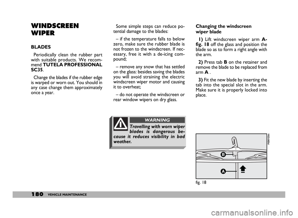
1)Lift windscreen wiper arm A-
fig. 18off the glass and position the
blade so as to form a right angle with
the arm.
2) Press tab Bon the retainer and
remove the blade to be replaced from
arm A .
3)Fit the new blade by inserting the
tab into the special slot in the arm.
Make sure it is properly locked into
place.
fig. 18
F0D0123m
Some simple steps can reduce po-
tential damage to the blades:
– if the temperature falls to below
zero, make sure the rubber blade is
not frozen to the windscreen. If nec-
essary, free it with a de-icing com-
pound;
– remove any snow that has settled
on the glass: besides saving the blades
you will avoid straining the electric
windscreen wiper motor and causing
it to overheat;
– do not operate the windscreen or
rear window wipers on dry glass.
Travelling with worn wiper
blades is dangerous be-
cause it reduces visibility in bad
weather.
WARNING
Page 182 of 258
181VEHICLE MAINTENANCE
SPRAY NOZZLES
Windscreen washer
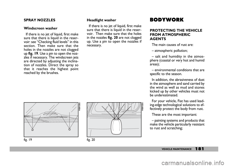
If there is no jet of liquid, first make
sure that there is liquid in the reser-
voir: see “Checking fluid levels” in this
section. Then make sure that the
holes in the nozzles are not clogged
upfig. 19. Use a pin to open the noz-
zles if necessary. The windscreen jets
are directed by adjusting the inclina-
tion of nozzles. Direct the spray so
that it reaches the highest point
reached by the brushes.Headlight washer
If there is no jet of liquid, first make
sure that there is liquid in the reser-
voir. Then make sure that the holes
in the nozzles fig. 20are not clogged
up. Use a pin to open the nozzles if
necessary.BODYWORK
PROTECTING THE VEHICLE
FROM ATMOSPHERIC
AGENTS
The main causes of rust are:
– atmospheric pollution;
– salt and humidity in the atmos-
phere (coastal or very hot and humid
areas);
– environmental conditions that are
specific to the season.
In addition, the abrasiveness of dust
in the atmosphere and sand carried by
the wind as well as mud and stones
kicked up by other vehicles must not
be underestimated.
For your vehicle, Fiat has used lead-
ing-edge technological solutions to ef-
fectively protect the body from rust.
These are the most important:
– painting systems and products that
make the vehicle particularly resistant
to rust and scratching;
fig. 20
F0D0122m
fig. 19
F0D0125m
Page 185 of 258
184VEHICLE MAINTENANCE
INTERIORS
From time to time check that water
has not collected under the mats
(from dripping shoes, umbrellas, etc.)
which could cause the steel to rust.
CLEANING SEATS
AND FABRICS
Remove dust with a soft brush and
vacuum cleaner. For velvet seats use
a damp brush.
Brush the seats with a damp sponge
with water and neutral soap.PLASTIC PARTS INSIDE
THE VEHICLE
Clean plastic parts with damp cloth
with water and non-abrasive neutral
soap. To remove grease or hard
stains, use special solvent-free prod-
ucts designed not to alter the appear-
ance and colour of components.
IMPORTANTDo not use alcohol
or petrol to clean the instrument
panel.
Never use flammable prod-
ucts (petroleum ether or
petrol) to clean the inside of the ve-
hicle. Electrostatic charges gener-
ated by rubbing while cleaning
could cause fires.
WARNING
Do not keep aerosol cans in
the vehicle. There is the risk
they might explode. Aerosol cans
must never be exposed to a tem-
perature above 50°C; when the
weather starts to get hot the tem-
perature inside the vehicle might go
well beyond that figure.
WARNING
Page 186 of 258
185TECHNICAL SPECIFICATIONS
T T
E E
C C
H H
N N
I I
C C
A A
L L
S S
P P
E E
C C
I I
F F
I I
C C
A A
T T
I I
O O
N N
S S
VEHICLE
IDENTIFICATION
DATA
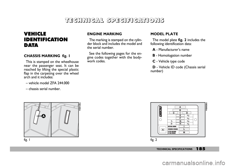
CHASSIS MARKING fig. 1
This is stamped on the wheelhouse
near the passenger seat. It can be
reached by lifting the special plastic
flap in the carpeting over the wheel
arch and it includes:
– vehicle model ZFA 244.000
– chassis serial number.ENGINE MARKING
The marking is stamped on the cylin-
der block and includes the model and
the serial number.
See the following pages for the en-
gine codes together with the body-
work codes.MODEL PLATE
The model plate fig. 2includes the
following identification data:
A - Manufacturer’s name
B - Homologation number
C - Vehicle type code
D- Vehicle ID code (Chassis serial
number)
fig. 1
F0D0126m
fig. 2
F0D0026m
Page 187 of 258
186TECHNICAL SPECIFICATIONS
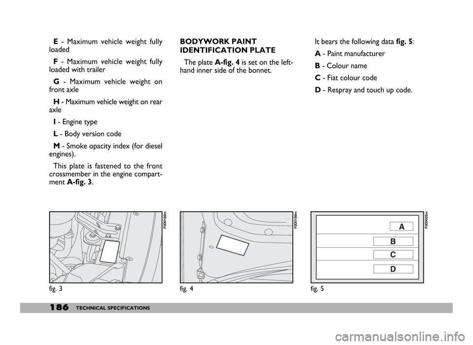
E- Maximum vehicle weight fully
loaded
F - Maximum vehicle weight fully
loaded with trailer
G - Maximum vehicle weight on
front axle
H - Maximum vehicle weight on rear
axle
I - Engine type
L - Body version code
M - Smoke opacity index (for diesel
engines).
This plate is fastened to the front
crossmember in the engine compart-
ment A-fig. 3.BODYWORK PAINT
IDENTIFICATION PLATE
The plateA-fig. 4 is set on the left-
hand inner side of the bonnet.It bears the following data fig. 5:
A - Paint manufacturer
B - Colour name
C - Fiat colour code
D- Respray and touch up code.
fig. 3
F0D0188m
fig. 4
F0D0189m
fig. 5
F0D0025m
Page 220 of 258
219TECHNICAL SPECIFICATIONS
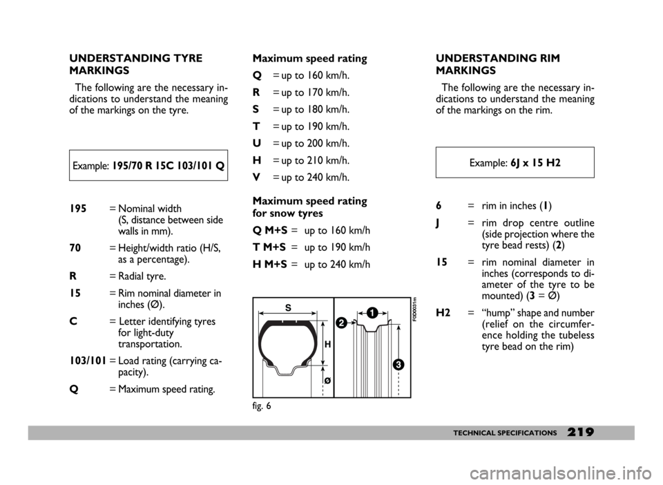
UNDERSTANDING TYRE
MARKINGS
The following are the necessary in-
dications to understand the meaning
of the markings on the tyre.
195= Nominal width
(S, distance between side
walls in mm).
70= Height/width ratio (H/S,
as a percentage).
R= Radial tyre.
15= Rim nominal diameter in
inches (Ø).
C= Letter identifying tyres
for light-duty
transportation.
103/101= Load rating (carrying ca-
pacity).
Q= Maximum speed rating.6= rim in inches (1)
J= rim drop centre outline
(side projection where the
tyre bead rests) (2)
15= rim nominal diameter in
inches (corresponds to di-
ameter of the tyre to be
mounted) (3 = Ø)
H2= “hump” shape and number
(relief on the circumfer-
ence holding the tubeless
tyre bead on the rim) Maximum speed rating
Q= up to 160 km/h.
R= up to 170 km/h.
S= up to 180 km/h.
T= up to 190 km/h.
U= up to 200 km/h.
H= up to 210 km/h.
V= up to 240 km/h.
Maximum speed rating
for snow tyres
Q M+S= up to 160 km/h
T M+S= up to 190 km/h
H M+S= up to 240 km/hUNDERSTANDING RIM
MARKINGS
The following are the necessary in-
dications to understand the meaning
of the markings on the rim.
Example: 195/70 R 15C 103/101 QExample: 6J x 15 H2
fig. 6
F0D0031m
Page 223 of 258
222TECHNICAL SPECIFICATIONS
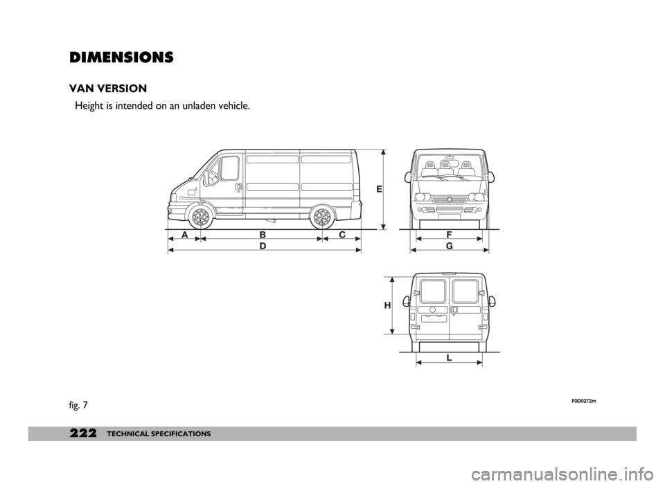
DIMENSIONS
VAN VERSION
Height is intended on an unladen vehicle.
fig. 7F0D0272m
Page 225 of 258
224TECHNICAL SPECIFICATIONS
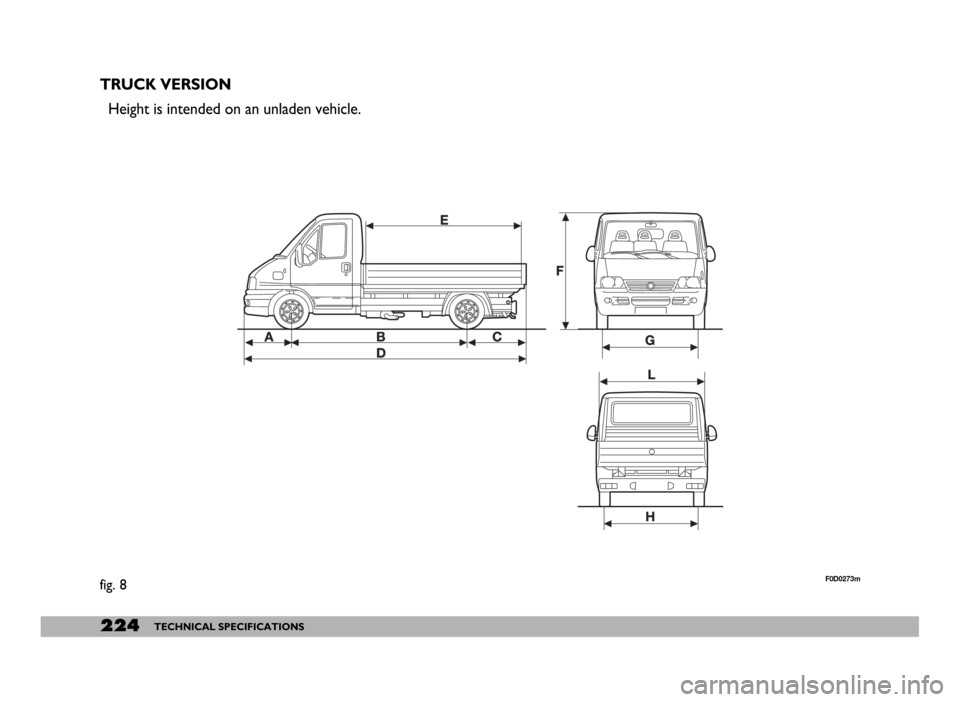
TRUCK VERSION
Height is intended on an unladen vehicle.
fig. 8F0D0273m
Page 228 of 258
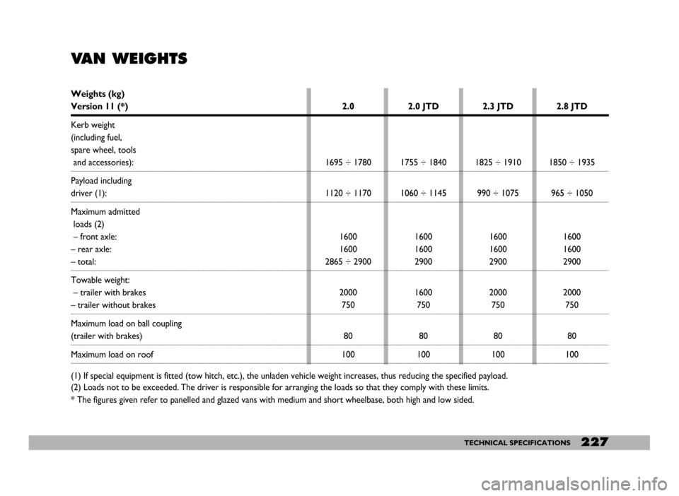
227TECHNICAL SPECIFICATIONS
VAN WEIGHTS
Weights (kg)
Version 11 (*)
Kerb weight
(including fuel,
spare wheel, tools
and accessories):
Payload including
driver (1):
Maximum admitted
loads (2)
– front axle:
– rear axle:
– total:
Towable weight:
– trailer with brakes
– trailer without brakes
Maximum load on ball coupling
(trailer with brakes)
Maximum load on roof
(1) If special equipment is fitted (tow hitch, etc.), the unladen vehicle weight increases, thus reducing the specified payload.
(2) Loads not to be exceeded. The driver is responsible for arranging the loads so that they comply with these limits.
* The figures given refer to panelled and glazed vans with medium and short wheelbase, both high and low sided.2.0
1695 ÷ 1780
1120 ÷ 1170
1600
1600
2865 ÷ 2900
2000
750
80
1002.0 JTD
1755 ÷ 1840
1060 ÷ 1145
1600
1600
2900
1600
750
80
1002.3 JTD
1825 ÷ 1910
990 ÷ 1075
1600
1600
2900
2000
750
80
1002.8 JTD
1850 ÷ 1935
965 ÷ 1050
1600
1600
2900
2000
750
80
100