fig 36 FIAT DUCATO 244 2005 3.G Owners Manual
[x] Cancel search | Manufacturer: FIAT, Model Year: 2005, Model line: DUCATO 244, Model: FIAT DUCATO 244 2005 3.GPages: 258, PDF Size: 4.05 MB
Page 137 of 258
136IN AN EMERGENCY
JUMP STARTING
If the battery is flat, you can use an-
other battery to start the engine. Its
capacity must be the same or slightly
greater than the flat battery.
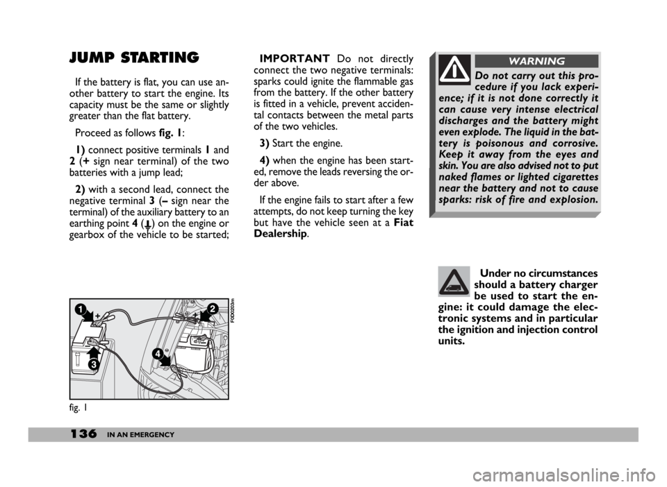
Proceed as follows fig. 1:
1) connect positive terminals1and
2 (+sign near terminal) of the two
batteries with a jump lead;
2) with a second lead, connect the
negative terminal 3(– sign near the
terminal) of the auxiliary battery to an
earthing point 4(E) on the engine or
gearbox of the vehicle to be started;IMPORTANTDo not directly
connect the two negative terminals:
sparks could ignite the flammable gas
from the battery. If the other battery
is fitted in a vehicle, prevent acciden-
tal contacts between the metal parts
of the two vehicles.
3) Start the engine.
4)when the engine has been start-
ed, remove the leads reversing the or-
der above.
If the engine fails to start after a few
attempts, do not keep turning the key
but have the vehicle seen at a Fiat
Dealership.
fig. 1
F0D0203m
Under no circumstances
should a battery charger
be used to start the en-
gine: it could damage the elec-
tronic systems and in particular
the ignition and injection control
units.
Do not carry out this pro-
cedure if you lack experi-
ence; if it is not done correctly it
can cause very intense electrical
discharges and the battery might
even explode. The liquid in the bat-
tery is poisonous and corrosive.
Keep it away from the eyes and
skin. You are also advised not to put
naked flames or lighted cigarettes
near the battery and not to cause
sparks: risk of fire and explosion.
WARNING
Page 140 of 258
139IN AN EMERGENCY
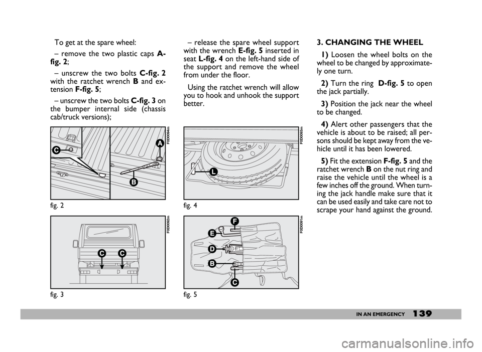
To get at the spare wheel:
– remove the two plastic caps A-
fig. 2;
– unscrew the two bolts C-fig. 2
with the ratchet wrench B and ex-
tension F-fig. 5;
– unscrew the two bolts C-fig. 3on
the bumper internal side (chassis
cab/truck versions);– release the spare wheel support
with the wrench E-fig. 5inserted in
seatL-fig. 4 on the left-hand side of
the support and remove the wheel
from under the floor.
Using the ratchet wrench will allow
you to hook and unhook the support
better.3. CHANGING THE WHEEL
1) Loosen the wheel bolts on the
wheel to be changed by approximate-
ly one turn.
2) Turn the ring D-fig. 5 to open
the jack partially.
3)Position the jack near the wheel
to be changed.
4) Alert other passengers that the
vehicle is about to be raised; all per-
sons should be kept away from the ve-
hicle until it has been lowered.
5)Fit the extension F-fig. 5and the
ratchet wrench Bon the nut ring and
raise the vehicle until the wheel is a
few inches off the ground. When turn-
ing the jack handle make sure that it
can be used easily and take care not to
scrape your hand against the ground.
fig. 2
F0D0094m
fig. 3
F0D0092m
fig. 4
F0D0093m
fig. 5
F0D0091m
Page 141 of 258
140IN AN EMERGENCY
The moving parts of the jack (screw
and joints) may also cause injury if
touched. Clean off any grease.
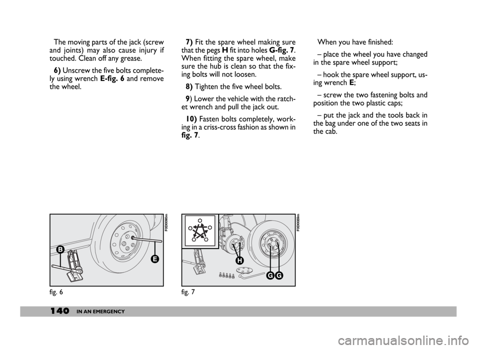
6)Unscrew the five bolts complete-
ly using wrench E-fig. 6and remove
the wheel.7) Fit the spare wheel making sure
that the pegs Hfit into holes G-fig. 7.
When fitting the spare wheel, make
sure the hub is clean so that the fix-
ing bolts will not loosen.
8)Tighten the five wheel bolts.
9) Lower the vehicle with the ratch-
et wrench and pull the jack out.
10)Fasten bolts completely, work-
ing in a criss-cross fashion as shown in
fig. 7.
fig. 6
F0D0090m
fig. 7
F0D0089m
When you have finished:
– place the wheel you have changed
in the spare wheel support;
– hook the spare wheel support, us-
ing wrench E;
– screw the two fastening bolts and
position the two plastic caps;
– put the jack and the tools back in
the bag under one of the two seats in
the cab.
Page 143 of 258
142IN AN EMERGENCY
Bulbs
Main beam headlights
Dipped beam headlights
Front side lights
Front direction indicators
Side direction indicators
Rear direction indicators
Brake lights
Third brake light
Reversing light
Rear fog light/taillights
Front ceiling light
Rear ceiling light
Number plate lightW
60/55 W
60/55 W
5 W
21 W
5 W
21 W
21 W
21 W
21 W
21 W
10 W
15 W
5 W Type
H4
H4
R5W
P21W
W5W
PY21W
P21W
P21W
P21W
P21/4W
CW10
CW15
CW5
Figure
D
D
B
B
A
B
B
B
B
B
C
C
B
fig. 8
F0D0090m
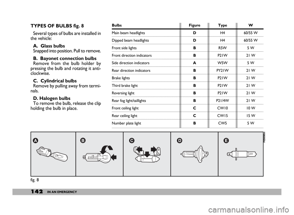
TYPES OF BULBS fig. 8
Several types of bulbs are installed in
the vehicle:
A. Glass bulbs
Snapped into position. Pull to remove.
B. Bayonet connection bulbs
Remove from the bulb holder by
pressing the bulb and rotating it anti-
clockwise.
C. Cylindrical bulbs
Remove by pulling away from termi-
nals.
D. Halogen bulbs
To remove the bulb, release the clip
holding the bulb in place.
Page 144 of 258
143IN AN EMERGENCY
MAIN AND DIPPED BEAM
HEADLIGHTS
To replace a halogen bulb with head-
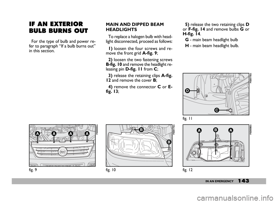
light disconnected, proceed as follows:
1)loosen the four screws and re-
move the front grid A-fig. 9;
2)loosen the two fastening screws
B-fig. 10and remove the headlight re-
leasing pin D-fig. 11from C;
3)release the retaining clips A-fig.
12and remove the cover B;
4)remove the connector Cor E-
fig. 13;5)release the two retaining clips D
or F-fig. 14and remove bulbs Gor
H-fig. 14.
G- main beam headlight bulb
H- main beam headlight bulb.
fig. 12
F0D0096m
fig. 11
F0D0176m
fig. 10
F0D0175m
IF AN EXTERIOR
BULB BURNS OUT
For the type of bulb and power re-
fer to paragraph “If a bulb burns out”
in this section.
fig. 9
F0D0000m
Page 145 of 258
144IN AN EMERGENCY
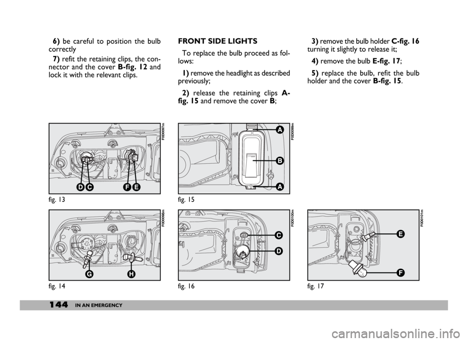
3)remove the bulb holder C-fig. 16
turning it slightly to release it;
4)remove the bulb E-fig. 17;
5) replace the bulb, refit the bulb
holder and the cover B-fig. 15. 6)be careful to position the bulb
correctly
7)refit the retaining clips, the con-
nector and the cover B-fig. 12and
lock it with the relevant clips.
fig. 15
F0D0099m
fig. 16
F0D0100m
fig. 17
F0D0101m
FRONT SIDE LIGHTS
To replace the bulb proceed as fol-
lows:
1)remove the headlight as described
previously;
2)release the retaining clips A-
fig. 15and remove the cover B;
fig. 13
F0D0097m
fig. 14
F0D0098m
Page 146 of 258
145IN AN EMERGENCY
REAR LIGHT CLUSTER
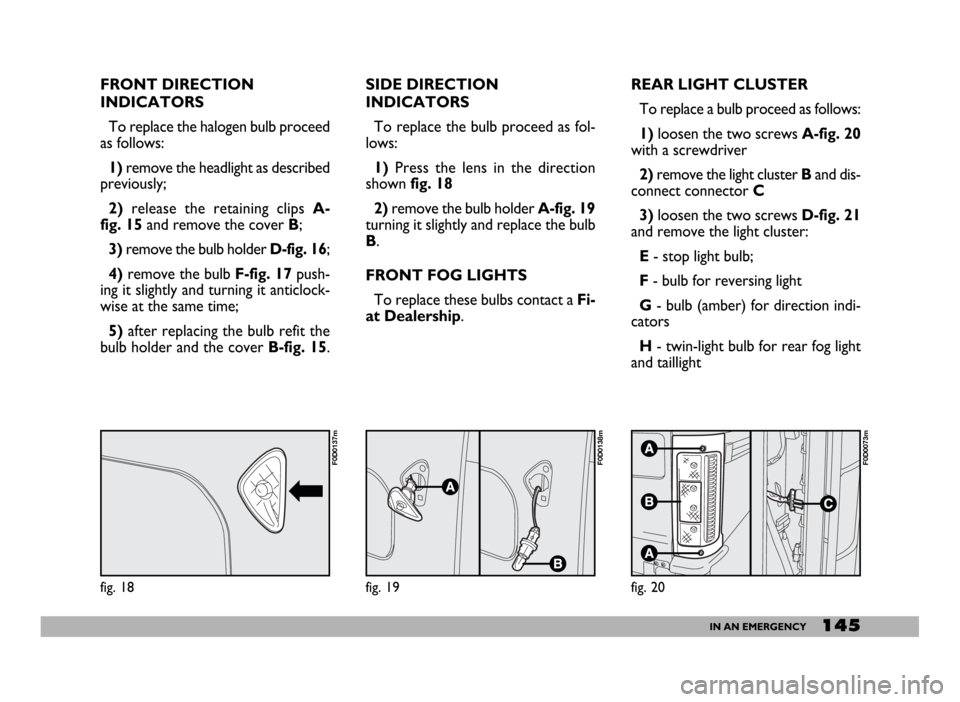
To replace a bulb proceed as follows:
1)loosen the two screws A-fig. 20
with a screwdriver
2)remove the light cluster Band dis-
connect connector C
3)loosen the two screws D-fig. 21
and remove the light cluster:
E- stop light bulb;
F- bulb for reversing light
G - bulb (amber) for direction indi-
cators
H- twin-light bulb for rear fog light
and taillight
fig. 20
F0D0073m
FRONT DIRECTION
INDICATORS
To replace the halogen bulb proceed
as follows:
1) remove the headlight as described
previously;
2)release the retaining clips A-
fig. 15 and remove the cover B;
3)remove the bulb holder D-fig. 16;
4)remove the bulb F-fig. 17push-
ing it slightly and turning it anticlock-
wise at the same time;
5)after replacing the bulb refit the
bulb holder and the cover B-fig. 15.SIDE DIRECTION
INDICATORS
To replace the bulb proceed as fol-
lows:
1)Press the lens in the direction
shown fig. 18
2)remove the bulb holder A-fig. 19
turning it slightly and replace the bulb
B.
FRONT FOG LIGHTS
To replace these bulbs contact a Fi-
at Dealership.
fig. 18
F0D0137m
fig. 19
F0D0138m
Page 147 of 258
146IN AN EMERGENCY
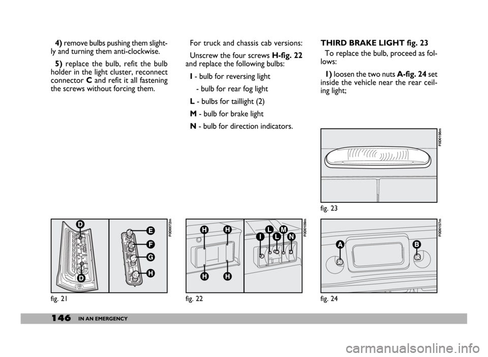
THIRD BRAKE LIGHT fig. 23
To replace the bulb, proceed as fol-
lows:
1)loosen the two nuts A-fig. 24set
inside the vehicle near the rear ceil-
ing light; 4)remove bulbs pushing them slight-
ly and turning them anti-clockwise.
5) replace the bulb, refit the bulb
holder in the light cluster, reconnect
connector Cand refit it all fastening
the screws without forcing them.For truck and chassis cab versions:
Unscrew the four screws H-fig. 22
and replace the following bulbs:
I- bulb for reversing light
- bulb for rear fog light
L- bulbs for taillight (2)
M- bulb for brake light
N- bulb for direction indicators.
fig. 21
F0D0072m
fig. 22
F0D0109m
fig. 23
F0D0156m
fig. 24
F0D0157m
Page 148 of 258
147IN AN EMERGENCY
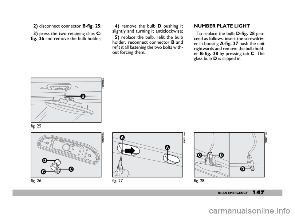
NUMBER PLATE LIGHT
To replace the bulb D-fig. 28pro-
ceed as follows: insert the screwdriv-
er in housing A-fig. 27push the unit
rightwards and remove the bulb hold-
er B-fig. 28by pressing tab C. The
glass bulb Dis clipped in. 2)disconnect connector B-fig. 25;
3)press the two retaining clips C-
fig. 26and remove the bulb holder;4)remove the bulb Dpushing it
slightly and turning it anticlockwise;
5)replace the bulb, refit the bulb
holder, reconnect connector Band
refit it all fastening the two bolts with-
out forcing them.
fig. 25
F0D0158m
fig. 26
F0D0159m
fig. 27
F0D0110m
fig. 28
F0D0111m
Page 149 of 258
148IN AN EMERGENCY
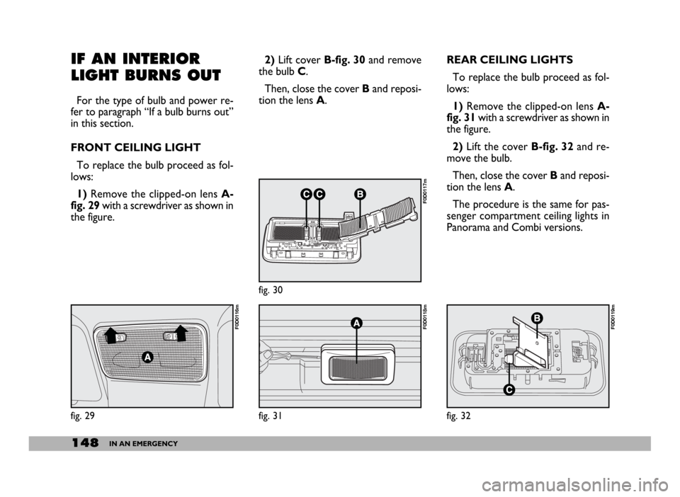
REAR CEILING LIGHTS
To replace the bulb proceed as fol-
lows:
1) Remove the clipped-on lens A-
fig. 31with a screwdriver as shown in
the figure.
2)Lift the cover B-fig. 32 and re-
move the bulb.
Then, close the cover Band reposi-
tion the lens A.
The procedure is the same for pas-
senger compartment ceiling lights in
Panorama and Combi versions.IF AN INTERIOR
LIGHT BURNS OUT
For the type of bulb and power re-
fer to paragraph “If a bulb burns out”
in this section.
FRONT CEILING LIGHT
To replace the bulb proceed as fol-
lows:
1) Remove the clipped-on lens A-
fig. 29with a screwdriver as shown in
the figure.2)Lift cover B-fig. 30and remove
the bulb C.
Then, close the cover Band reposi-
tion the lens A.
fig. 29
F0D0116m
fig. 30
F0D0117m
fig. 31
F0D0118m
fig. 32
F0D0119m