fig 36 FIAT DUCATO 244 2005 3.G Manual Online
[x] Cancel search | Manufacturer: FIAT, Model Year: 2005, Model line: DUCATO 244, Model: FIAT DUCATO 244 2005 3.GPages: 258, PDF Size: 4.05 MB
Page 110 of 258
109GETTING THE BEST OUT OF YOUR VEHICLE
To release the handbrake:
1)slightly lift the handbrake and press
release button A-fig. 1;
2)keep the button pressed and low-
er the lever. Warning light xwill go
out;
3)press the brake pedal when car-
rying out this operation to prevent the
vehicle moving accidentally.
IMPORTANTPull the handbrake
lever only when the vehicle is at a
standstill, or when the vehicle is run-
ning, but however only in case of a fail-
ure of the hydraulic system.
Should the handbrake be exception-
ally used when the vehicle is running, it
is suggested to keep a moderate trac-
tion to avoid causing the rear axle
block, entailing vehicle side skidding.USING THE
MANUAL GEARBOX
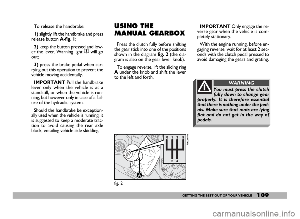
Press the clutch fully before shifting
the gear stick into one of the positions
shown in the diagram fig. 2(the dia-
gram is also on the gear lever knob).
To engage reverse, lift the sliding ring
Aunder the knob and shift the lever
to the left and forth.IMPORTANTOnly engage the re-
verse gear when the vehicle is com-
pletely stationary.
With the engine running, before en-
gaging reverse, wait for at least 2 sec-
onds with the clutch pedal pressed to
avoid damaging the gears and grating.
fig. 2
F0D0057m
You must press the clutch
fully down to change gear
properly. It is therefore essential
that there is nothing under the ped-
als. Make sure that mats are lying
flat and do not get in the way of
pedals.
WARNING
Page 111 of 258
110GETTING THE BEST OUT OF YOUR VEHICLE
STARTING
After starting the engine, with the en-
gine idling and keeping the brake ped-
al pressed, move the gearshift lever to
position D. Release the brake pedal
and gradually press the accelerator
pedal.
IMPORTANT Movement of the
lever from position Pis allowed only
with the ignition key at MARand the
button on the lever and the brake ped-
al pressed. STOPPING THE VEHICLE
To stop the vehicle, simply press the
brake pedal regardless of the position
of the gearshift lever.
IMPORTANTRemoving the igni-
tion key is only allowed with the
gearshift lever in position Pand for a
maximum time of 30 seconds from
when the engine is turned off P, when
the door is opened a buzzer will sound
for about 15 seconds to alert the dri-
ver.
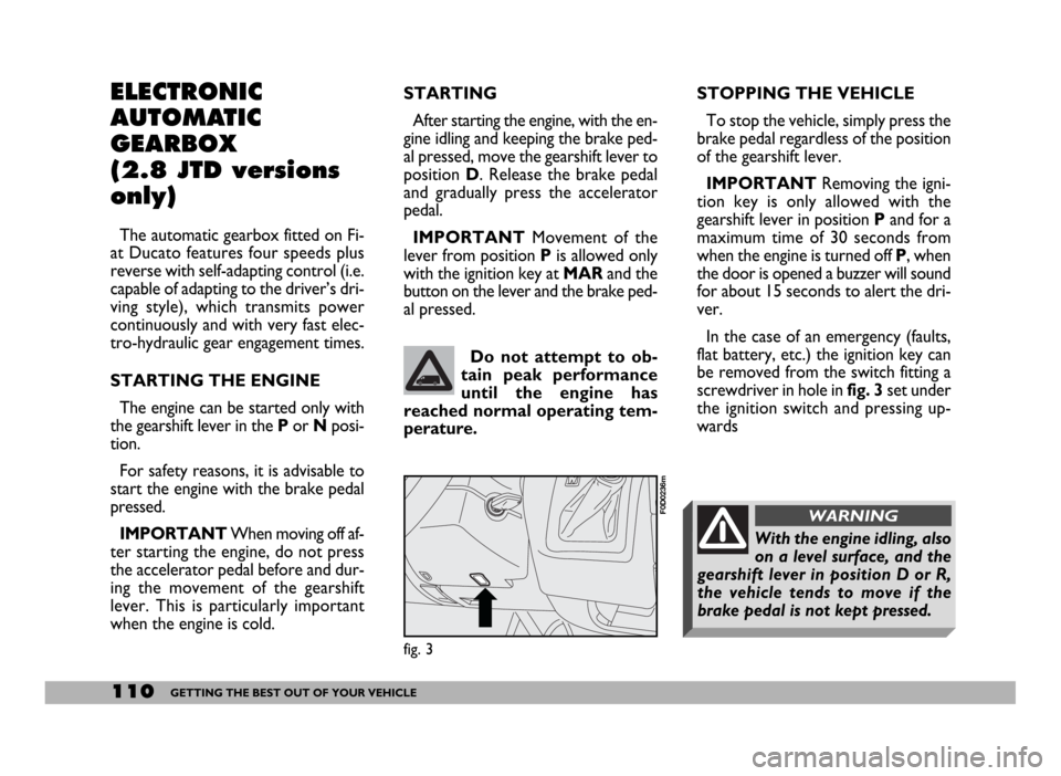
In the case of an emergency (faults,
flat battery, etc.) the ignition key can
be removed from the switch fitting a
screwdriver in hole infig. 3set under
the ignition switch and pressing up-
wards Do not attempt to ob-
tain peak performance
until the engine has
reached normal operating tem-
perature.
fig. 3
F0D0236m
With the engine idling, also
on a level surface, and the
gearshift lever in position D or R,
the vehicle tends to move if the
brake pedal is not kept pressed.
WARNING
ELECTRONIC
AUTOMATIC
GEARBOX
(2.8 JTD versions
only)
The automatic gearbox fitted on Fi-
at Ducato features four speeds plus
reverse with self-adapting control (i.e.
capable of adapting to the driver’s dri-
ving style), which transmits power
continuously and with very fast elec-
tro-hydraulic gear engagement times.
STARTING THE ENGINE
The engine can be started only with
the gearshift lever in the P or Nposi-
tion.
For safety reasons, it is advisable to
start the engine with the brake pedal
pressed.
IMPORTANTWhen moving off af-
ter starting the engine, do not press
the accelerator pedal before and dur-
ing the movement of the gearshift
lever. This is particularly important
when the engine is cold.
Page 112 of 258
111GETTING THE BEST OUT OF YOUR VEHICLE
SELECTING AUTOMATIC/
SEQUENTIAL MANUAL
OPERATION
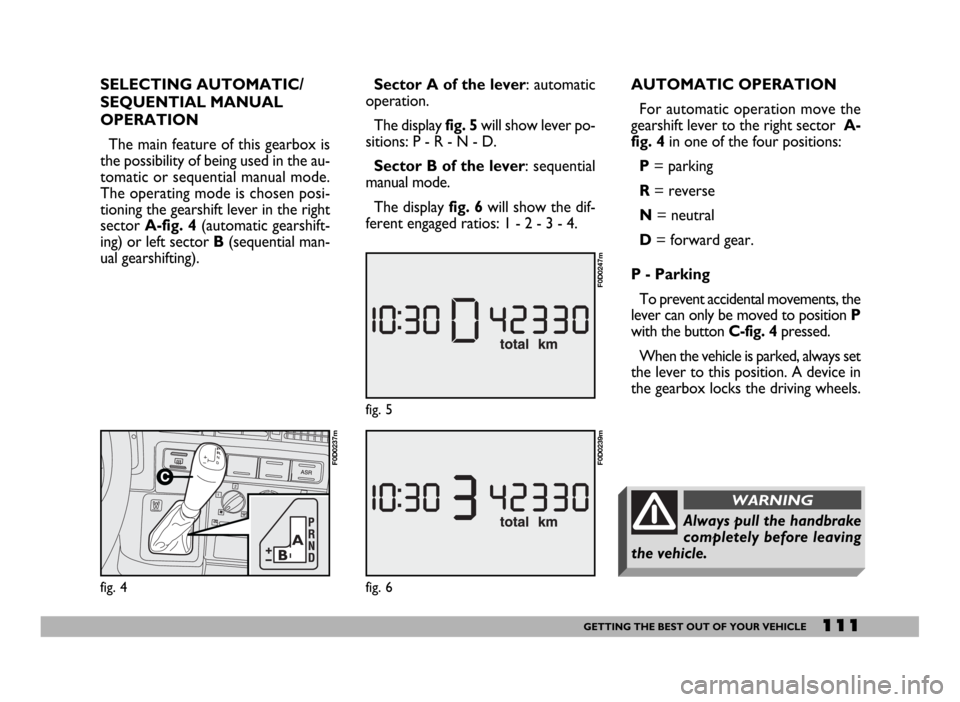
The main feature of this gearbox is
the possibility of being used in the au-
tomatic or sequential manual mode.
The operating mode is chosen posi-
tioning the gearshift lever in the right
sector A-fig. 4(automatic gearshift-
ing) or left sector B(sequential man-
ual gearshifting).
fig. 4
F0D0237m
Sector A of the lever: automatic
operation.
The display fig. 5will show lever po-
sitions: P - R - N - D.
Sector B of the lever: sequential
manual mode.
The display fig. 6will show the dif-
ferent engaged ratios: 1 - 2 - 3 - 4.AUTOMATIC OPERATION
For automatic operation move the
gearshift lever to the right sector A-
fig. 4in one of the four positions:
P= parking
R= reverse
N= neutral
D= forward gear.
P - Parking
To prevent accidental movements, the
lever can only be moved to position P
with the button C-fig. 4pressed.
When the vehicle is parked, always set
the lever to this position. A device in
the gearbox locks the driving wheels.
fig. 6
F0D0239m
fig. 5
F0D0247m
Always pull the handbrake
completely before leaving
the vehicle.
WARNING
Page 113 of 258
112GETTING THE BEST OUT OF YOUR VEHICLE
IMPORTANTRemoving the igni-
tion key is only allowed with the
gearshift lever in position Pand for a
maximum time of 30 seconds from
when the engine is turned off P, when
the door is opened a buzzer will sound
for about 15 seconds to alert the dri-
ver.
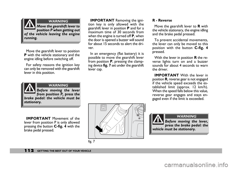
In an emergency (flat battery) it is
possible to move the gearshift lever
from position P, pressing the clamp-
ing device fig. 7set under the gearshift
lever cap.R - Reverse
Move the gearshift lever to Rwith
the vehicle stationary, the engine idling
and the brake pedal pressed.
To prevent accidental movements,
the lever can only be moved to this
position with the button C-fig. 4
pressed.
With the lever in position Rthe re-
verse lights turn on and a buzzer
sounds for about 4 seconds to warn
the driver.
IMPORTANTWith the lever in
position R, reverse gear is not engaged
if the vehicle speed exceeds the es-
tablished limit (approx. 12 km/h).
When the speed falls below this value,
reverse gear engages and stays en-
gaged even if the limit is exceeded.
fig. 7
F0D0240m
Before moving the lever,
press the brake pedal: the
vehicle must be stationary.
WARNING
Move the gearshift lever to position
Pwith the vehicle stationary and the
engine idling before switching off.
For safety reasons the ignition key
can only be removed with the gearshift
lever in this position.
IMPORTANTMovement of the
lever from position P is only allowed
pressing the button C-fig. 4with the
brake pedal pressed.
Move the gearshift lever to
position P when getting out
of the vehicle leaving the engine
running.
WARNING
Before moving the lever
from position P, press the
brake pedal: the vehicle must be
stationary.
WARNING
Page 115 of 258
114GETTING THE BEST OUT OF YOUR VEHICLE
SEQUENTIAL MANUAL
OPERATION
For the sequential manual operation
mode, move the lever to the left sec-
tor B-fig. 4with two positions:
(+) = engagement of the higher ra-
tio;
(–) = engagement of the lower ratio.
Moving the gearshift lever to the
manual sector is only possible from
position D: the ratio selected by the
automatic gearbox when the lever is
moved will remain engaged.
When the sequential manual mode is
selected, the display shows the en-
gaged gear fig. 6.
To select the higher ratio move the
lever in the (+) direction and to shift
down move the lever to (–).IMPORTANTIf the request to
downshift would cause engine
overevving, this is eliminated by the
electronic control unit. Moreover, if
the manually engaged gear causes en-
gine overevving, the electronic control
unit will shift gear automatically to the
most appropriate one (AUTO-UP).
When the sequential man-
ual mode has been set and
a high gear is engaged, to acceler-
ate rapidly, for example to over-
take, it is necessary to downshift
by hand: the kickdown feature
cannot be engaged!
WARNING
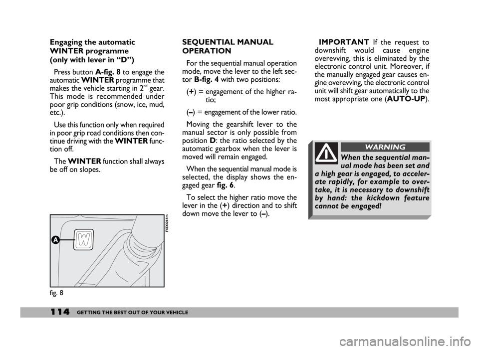
Engaging the automatic
WINTER programme
(only with lever in “D”)
Press button A-fig. 8to engage the
automatic WINTERprogramme that
makes the vehicle starting in 2
ndgear.
This mode is recommended under
poor grip conditions (snow, ice, mud,
etc.).
Use this function only when required
in poor grip road conditions then con-
tinue driving with the WINTERfunc-
tion off.
The WINTERfunction shall always
be off on slopes.
fig. 8
F0D0241m
Page 116 of 258
115GETTING THE BEST OUT OF YOUR VEHICLE
Moving the lever back to position D
the gearbox instantly resumes the au-
tomatic mode selecting the ratio ac-
cording to the driving characteristics.
IMPORTANTThe electronic con-
trol unit is programmed to change
gear one at a time, therefore repeat-
ed fast actuations will not result in re-
peated engagements of the gears. The
higher or lower gear is engaged mov-
ing the lever to the (+) or (–) position
when the previous request has been
performed.
In the event of a fault to the sequen-
tial manual system, the system will se-
lect the automatic mode.FAILURE INDICATIONS
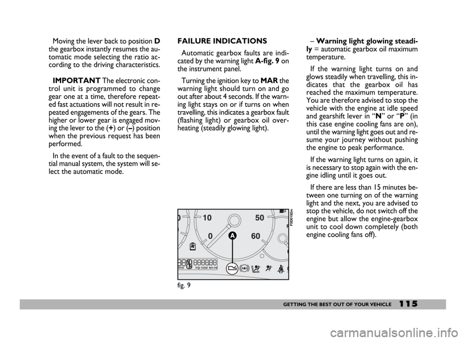
Automatic gearbox faults are indi-
cated by the warning light A-fig. 9 on
the instrument panel.
Turning the ignition key to MARthe
warning light should turn on and go
out after about 4 seconds. If the warn-
ing light stays on or if turns on when
travelling, this indicates a gearbox fault
(flashing light) or gearbox oil over-
heating (steadily glowing light).– Warning light glowing steadi-
ly= automatic gearbox oil maximum
temperature.
If the warning light turns on and
glows steadily when travelling, this in-
dicates that the gearbox oil has
reached the maximum temperature.
You are therefore advised to stop the
vehicle with the engine at idle speed
and gearshift lever in “N” or “P” (in
this case engine cooling fans are on),
until the warning light goes out and re-
sume your journey without pushing
the engine to peak performance.
If the warning light turns on again, it
is necessary to stop again with the en-
gine idling until it goes out.
If there are less than 15 minutes be-
tween one turning on of the warning
light and the next, you are advised to
stop the vehicle, do not switch off the
engine but allow the engine-gearbox
unit to cool down completely (both
engine cooling fans off).
fig. 9
F0D0192m
Page 127 of 258
126GETTING THE BEST OUT OF YOUR VEHICLE
CONDITIONS OF USE
Cold starting
Frequent cold starting will not enable
the engine to reach optimal running
temperature. It follows, therefore,
that consumption will be higher (from
+15 to +30% in towns) as will the
production of toxic emissions.
Traffic and road conditions
Heavy traffic and higher consumption
are synonymous: for example, when
driving slowly with frequent use of low-
er gears or in towns where there are
numerous traffic lights.
Winding roads, mountain roads and
bumpy roads also have a negative effect
on consumption.
Enforced halts
During prolonged stops (traffic lights,
level crossings, etc.) the engine should
be switched off.LOAD
RECOMMENDATIONS
The version of the Ducato you are
driving has been designed and ap-
proved on the basis of several set
maximum weights (see the tables
“Weights” in section “Technical spec-
ifications”):
– kerb weight
– payload
– total weight
– total weight on the front axle
– total weight on the rear axle
– towable weight
fig. 10
F0D0047m
Each of these limits must be
borne in mind and MUST
NEVER BE EXCEEDED under any
circumstances. In particular, never
exceed the maximum weight per-
mitted on the front and rear axles
when arranging loads in vehicle (es-
pecially for special version vehicles).
WARNING
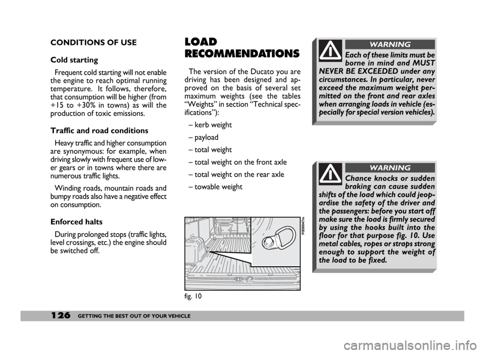
Chance knocks or sudden
braking can cause sudden
shifts of the load which could jeop-
ardise the safety of the driver and
the passengers: before you start off
make sure the load is firmly secured
by using the hooks built into the
floor for that purpose fig. 10. Use
metal cables, ropes or straps strong
enough to support the weight of
the load to be fixed.
WARNING
Page 131 of 258
130GETTING THE BEST OUT OF YOUR VEHICLE
The electrical brake or other device
(electrical winch, etc.) must be pow-
ered directly from the battery by
means of a lead with a cross-section
area not smaller than 2.5 mm
2.
In addition to the electrical connec-
tions, only the power wire for an ad-
ditional electrical brake and for inter-
nal trailer lighting with a power not
exceeding 15W can be connected to
the vehicle’s electrical system.
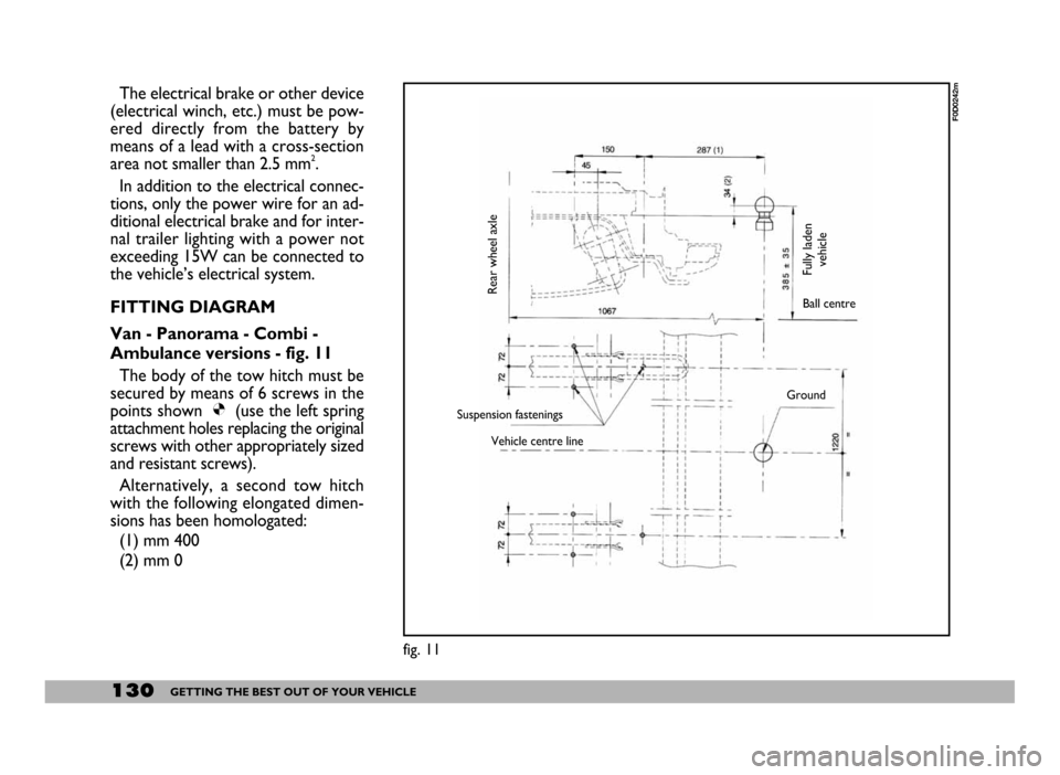
FITTING DIAGRAM
Van - Panorama - Combi -
Ambulance versions - fig. 11
The body of the tow hitch must be
secured by means of 6 screws in the
points shown Ø(use the left spring
attachment holes replacing the original
screws with other appropriately sized
and resistant screws).
Alternatively, a second tow hitch
with the following elongated dimen-
sions has been homologated:
(1) mm 400
(2) mm 0
fig. 11
F0D0242m
Rear wheel axle
Fully laden
vehicleBall centre
Suspension fastenings
Vehicle centre lineGround
Page 132 of 258
131GETTING THE BEST OUT OF YOUR VEHICLE
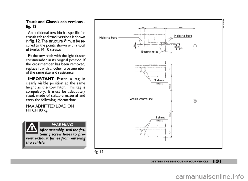
Truck and Chassis cab versions -
fig. 12
An additional tow hitch - specific for
chassis cab and truck versions is shown
in fig. 12. The structure Ømust be se-
cured to the points shown with a total
of twelve M 10 screws.
Fit the tow hitch with the light cluster
crossmember in its original position. If
the crossmember has been removed,
replace it with another crossmember
of the same size and resistance.
IMPORTANTFasten a tag in
clearly visible position at the same
height as the tow hitch. This tag is
compulsory. It must be adequately
sized, made of suitable material and
carry the following information:
MAX ADMITTED LOAD ON
HITCH 80 kg.
fig. 12
F0D0243m
Holes to boreHoles to bore
Existing holes
2 shims
Vehicle centre line
2 shims
After assembly, seal the fas-
tening screw holes to pre-
vent exhaust fumes from entering
the vehicle.
WARNING
Page 136 of 258
135IN AN EMERGENCY
I I
N N
A A
N N
E E
M M
E E
R R
G G
E E
N N
C C
Y Y
EMERGENCY
START-UP
DIESEL VERSIONS
Emergency start-ups cannot be per-
formed on versions with a diesel en-
gine; contact aFiat Dealership.
PETROL VERSIONS
If the Fiat CODE cannot deactivate
the engine immobiliser, the Yand
Uwarning lights stay on and the en-
gine will not start. Follow the emer-
gency start-up procedure to start the
engine.
Read the whole procedure care-
fully before trying to carry it out.
If you make a mistake, you must turn
the ignition key back to STOPand re-
peat the whole operation from the be-
ginning (step 1).1) Read the 5-figure electronic code
given on the CODE card.
2) Turn the ignition key to MAR.
3)Press and hold down the accel-
erator pedal. Warning light
Uwill
come on for about 8 seconds, and
then go out. At this point release the
accelerator pedal and get ready to
count the flashes of the warning light
U.
4) Count the number of flashes that
corresponds to the first figure of the
code on the CODE card, then press
the accelerator pedal and keep it there
until the warning light
Ucomes on
for four seconds and then goes out;
release the accelerator pedal.
5) Warning light
Uwill start flash-
ing again: after it has flashed the num-
ber of times that corresponds to the
second figure on the CODE card,
press the accelerator pedal and keep
it pressed.
6) Do the same for the remaining fig-
ures on the CODE card.7) Once the final figure has been en-
tered, keep the accelerator pedal
pressed. Warning light
Uwill light up
for four seconds and then go out; re-
lease the accelerator pedal.
8)Warning light
Uwill flash rapid-
ly for about 4 seconds to indicate that
the operation has been completed
correctly.
9) Start the engine by turning the ig-
nition key from MARto AVV.
If, however, the warning light
U
stays on, turn the ignition key to
STOPan repeat the procedure from
step 1).
IMPORTANT After an emergency
start-up, you should contact a Fiat
Dealership otherwise you will have
to repeat the procedure described
each time you want to start the en-
gine.