Dashboard FIAT DUCATO 244 2005 3.G User Guide
[x] Cancel search | Manufacturer: FIAT, Model Year: 2005, Model line: DUCATO 244, Model: FIAT DUCATO 244 2005 3.GPages: 258, PDF Size: 4.05 MB
Page 92 of 258
91GETTING TO KNOW YOUR VEHICLE
Therefore, failure to come into ac-
tion in the above circumstances does
not mean that the system is not work-
ing properly.
Airbag system efficiency is constant-
ly monitored by an electronic control
unit.
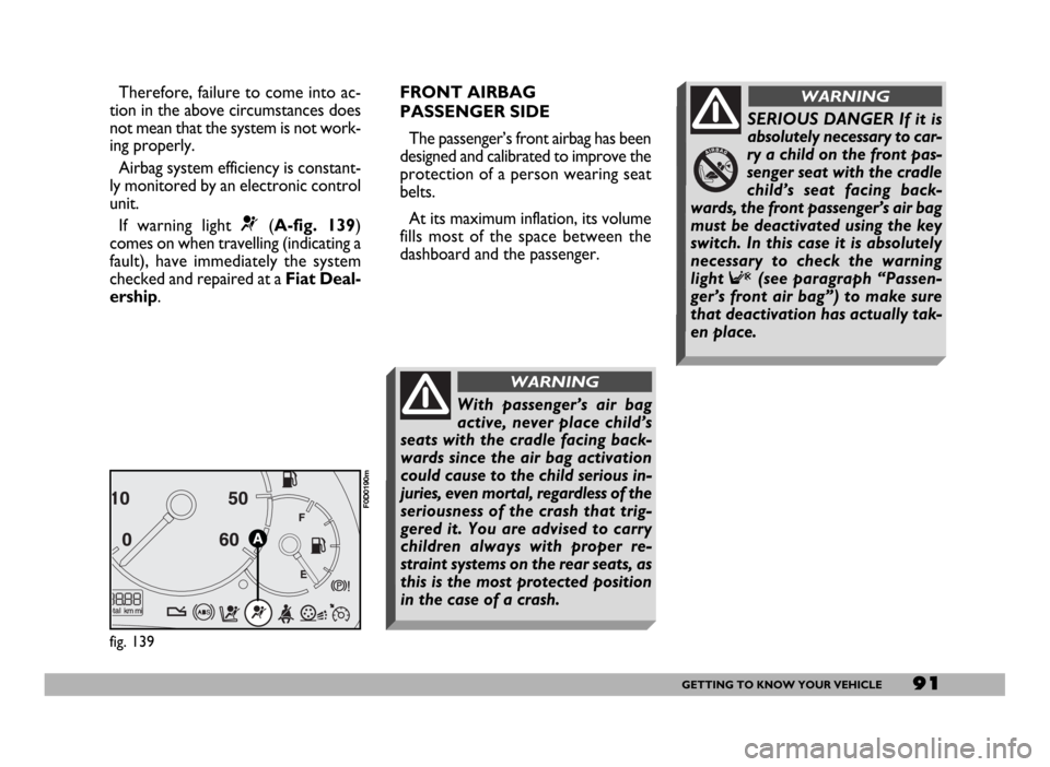
If warning light
¬(A-fig. 139)
comes on when travelling (indicating a
fault), have immediately the system
checked and repaired at a Fiat Deal-
ership.FRONT AIRBAG
PASSENGER SIDE
The passenger’s front airbag has been
designed and calibrated to improve the
protection of a person wearing seat
belts.
At its maximum inflation, its volume
fills most of the space between the
dashboard and the passenger.
fig. 139
F0D0190m
SERIOUS DANGER If it is
absolutely necessary to car-
ry a child on the front pas-
senger seat with the cradle
child’s seat facing back-
wards, the front passenger’s air bag
must be deactivated using the key
switch. In this case it is absolutely
necessary to check the warning
light
F(see paragraph “Passen-
ger’s front air bag”) to make sure
that deactivation has actually tak-
en place.
WARNING
With passenger’s air bag
active, never place child’s
seats with the cradle facing back-
wards since the air bag activation
could cause to the child serious in-
juries, even mortal, regardless of the
seriousness of the crash that trig-
gered it. You are advised to carry
children always with proper re-
straint systems on the rear seats, as
this is the most protected position
in the case of a crash.
WARNING
Page 99 of 258
98GETTING TO KNOW YOUR VEHICLE
SOUND SYSTEM
Visit a Fiat Dealership if
you want to fit a sound
system after buying the
vehicle. They can advise you on
how to safeguard battery life. Ex-
cessive idle intake can damage
the battery and may invalidate
the warranty.LIGHT SET-UP
The system consists of:
– radio power supply cables
– dashboard front speaker cables
– housing for the radio
– aerial and relevant wire
HEAVY SET-UP
The system consists of:
– radio power supply cables
– dashboard front speaker cables
– dashboard speakers
– door speaker cables
– door speakers
– housing for the radio
– aerial and relevant wire.
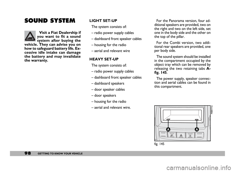
fig. 145
F0D0171m
For the Panorama version, four ad-
ditional speakers are provided, two on
the right and two on the left side, set
one in the body side and the other on
the top of the pillar.
For the Combi version, two addi-
tional rear speakers are provided, one
per body side.
The sound system should be installed
in the compartment occupied by the
object tray which can be removed by
releasing the two retaining tabs A-
fig. 145.
The power supply, speaker connec-
tion and aerial cables can be found in
this compartment.
Page 100 of 258
99GETTING TO KNOW YOUR VEHICLE
IMPORTANT The cables are se-
cured to the heater cables bundle with
adhesive tape to cut out noise.
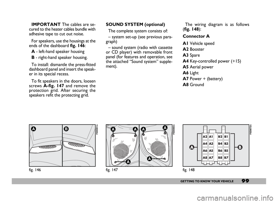
For speakers, use the housings at the
ends of the dashboard fig. 146:
A- left-hand speaker housing
B- right-hand speaker housing.
To install: dismantle the press-fitted
dashboard panel and insert the speak-
er in its special recess.
To fit speakers in the doors, loosen
screws A-fig. 147and remove the
protection grid. After securing the
speakers refit the protecting grid.
fig. 146
F0D0061m
SOUND SYSTEM (optional)
The complete system consists of:
– system set-up (see previous para-
graph)
– sound system (radio with cassette
or CD player) with removable front
panel (for features and operation, see
the attached “Sound system” supple-
ment).
fig. 147
F0D0060m
The wiring diagram is as follows
(fig. 148):
Connector A
A1Vehicle speed
A2Booster
A3Spare
A4Key-controlled power (+15)
A5Aerial power
A6Light
A7Power + (battery)
A8Ground
fig. 148
F0D0672m
Page 101 of 258
100GETTING TO KNOW YOUR VEHICLE
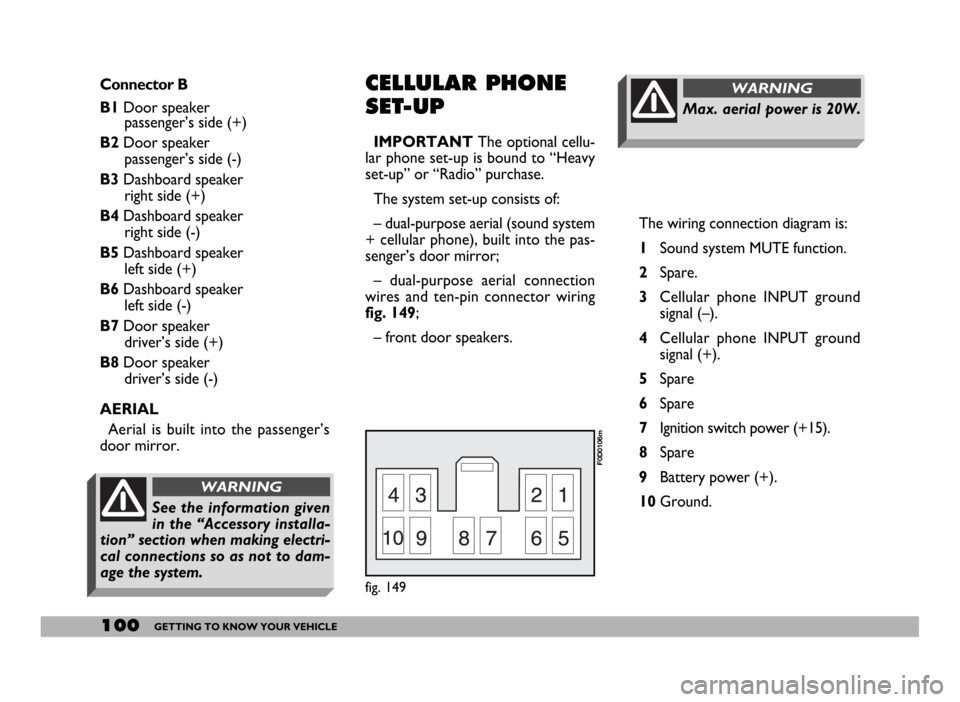
The wiring connection diagram is:
1Sound system MUTE function.
2Spare.
3Cellular phone INPUT ground
signal (–).
4Cellular phone INPUT ground
signal (+).
5Spare
6Spare
7Ignition switch power (+15).
8Spare
9Battery power (+).
10Ground.
Max. aerial power is 20W.
WARNINGConnector B
B1Door speaker
passenger’s side (+)
B2Door speaker
passenger’s side (-)
B3Dashboard speaker
right side (+)
B4Dashboard speaker
right side (-)
B5Dashboard speaker
left side (+)
B6Dashboard speaker
left side (-)
B7Door speaker
driver’s side (+)
B8Door speaker
driver’s side (-)
AERIAL
Aerial is built into the passenger’s
door mirror.CELLULAR PHONE
SET-UP
IMPORTANTThe optional cellu-
lar phone set-up is bound to “Heavy
set-up” or “Radio” purchase.
The system set-up consists of:
– dual-purpose aerial (sound system
+ cellular phone), built into the pas-
senger’s door mirror;
– dual-purpose aerial connection
wires and ten-pin connector wiring
fig. 149;
– front door speakers.
fig. 149
F0D0106m
See the information given
in the “Accessory installa-
tion” section when making electri-
cal connections so as not to dam-
age the system.
WARNING
Page 151 of 258
150IN AN EMERGENCY
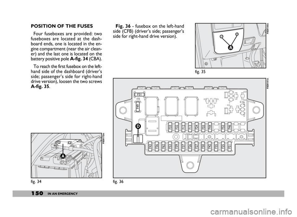
POSITION OF THE FUSES
Four fuseboxes are provided: two
fuseboxes are located at the dash-
board ends, one is located in the en-
gine compartment (near the air clean-
er) and the last one is located on the
battery positive pole A-fig. 34(CBA).
To reach the first fusebox on the left-
hand side of the dashboard (driver’s
side; passenger’s side for right-hand
drive version), loosen the two screws
A-fig. 35.Fig. 36- fusebox on the left-hand
side (CFB) (driver’s side; passenger’s
side for right-hand drive version).
fig. 34
F0D0172m
fig. 36
F0D0141m
fig. 35
F0D0144m
Page 152 of 258
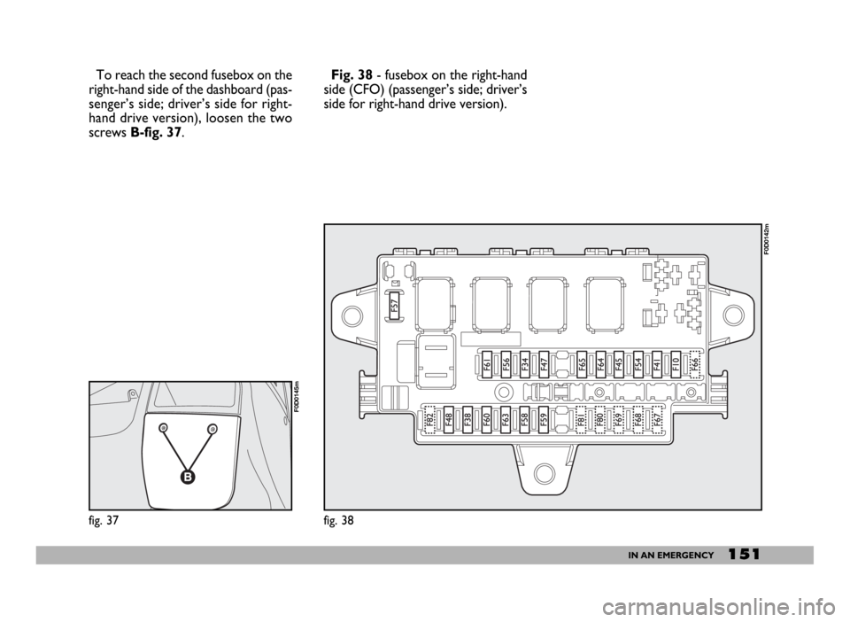
151IN AN EMERGENCY
To reach the second fusebox on the
right-hand side of the dashboard (pas-
senger’s side; driver’s side for right-
hand drive version), loosen the two
screws B-fig. 37.
fig. 37
F0D0145m
fig. 38
F0D0142m
Fig. 38- fusebox on the right-hand
side (CFO) (passenger’s side; driver’s
side for right-hand drive version).
Page 154 of 258
153IN AN EMERGENCY
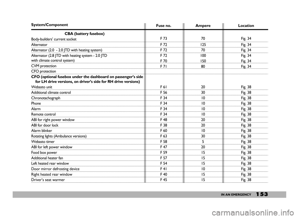
System/Component
CBA (battery fusebox)
Body-builders’ current socket
Alternator
Alternator (2.0 - 2.0 JTD with heating system)
Alternator (2.8 JTD with heating system - 2.0 JTD
with climate control system)
CVM protection
CFO protection
CFO (optional fusebox under the dashboard on passenger’s side
for LH drive versions, on driver’s side for RH drive versions)
Webasto unit
Additional climate control
Chronotachograph
Phone
Alarm
Remote control
ABI for right power window
ABI for door lock
Alarm blinker
Rotating lights (Ambulance versions)
Webasto timer
ABI for left power window
Food box power
Additional heater fan
Left heated rear window
Door mirror defrosting device
Right heated rear window
Driver’s seat warmerFuse no.
F 73
F 72
F 72
F 72
F 70
F 71
F 61
F 56
F 34
F 34
F 34
F 34
F 48
F 38
F 60
F 63
F 58
F 47
F 59
F 57
F 54
F 41
F 40
F 45Ampere
70
125
70
100
150
80
20
30
10
10
10
10
20
20
10
30
5
20
15
15
15
10
15
15Location
Fig. 34
Fig. 34
Fig. 34
Fig. 34
Fig. 34
Fig. 34
Fig. 38
Fig. 38
Fig. 38
Fig. 38
Fig. 38
Fig. 38
Fig. 38
Fig. 38
Fig. 38
Fig. 38
Fig. 38
Fig. 38
Fig. 38
Fig. 38
Fig. 38
Fig. 38
Fig. 38
Fig. 38
Page 155 of 258
154IN AN EMERGENCY
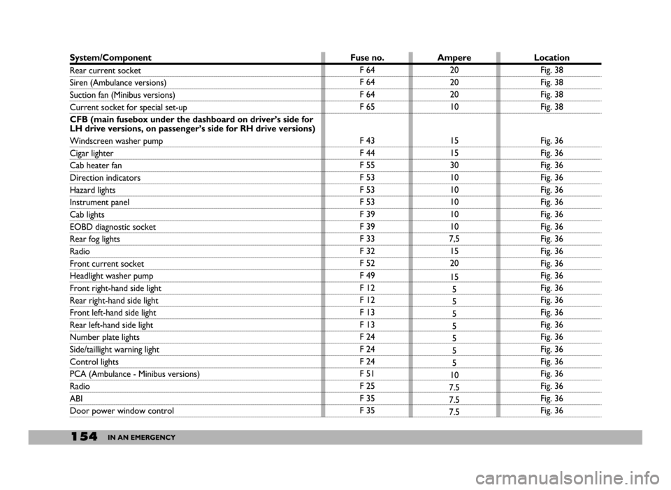
System/Component
Rear current socket
Siren (Ambulance versions)
Suction fan (Minibus versions)
Current socket for special set-up
CFB (main fusebox under the dashboard on driver’s side for
LH drive versions, on passenger’s side for RH drive versions)
Windscreen washer pump
Cigar lighter
Cab heater fan
Direction indicators
Hazard lights
Instrument panel
Cab lights
EOBD diagnostic socket
Rear fog lights
Radio
Front current socket
Headlight washer pump
Front right-hand side light
Rear right-hand side light
Front left-hand side light
Rear left-hand side light
Number plate lights
Side/taillight warning light
Control lights
PCA (Ambulance - Minibus versions)
Radio
ABI
Door power window controlLocation
Fig. 38
Fig. 38
Fig. 38
Fig. 38
Fig. 36
Fig. 36
Fig. 36
Fig. 36
Fig. 36
Fig. 36
Fig. 36
Fig. 36
Fig. 36
Fig. 36
Fig. 36
Fig. 36
Fig. 36
Fig. 36
Fig. 36
Fig. 36
Fig. 36
Fig. 36
Fig. 36
Fig. 36
Fig. 36
Fig. 36
Fig. 36 Ampere
20
20
20
10
15
15
30
10
10
10
10
10
7,5
15
20
15
5
5
5
5
5
5
5
10
7.5
7.5
7.5 Fuse no.
F 64
F 64
F 64
F 65
F 43
F 44
F 55
F 53
F 53
F 53
F 39
F 39
F 33
F 32
F 52
F 49
F 12
F 12
F 13
F 13
F 24
F 24
F 24
F 51
F 25
F 35
F 35
Page 249 of 258
248INDEX
Cruise Control ............................ 68
Current socket ............................ 76
Dashboard ................................. 5
Demisting ...................................... 56
Diesel fuel filter ........................... 173
Differential .................................... 216
Digital clock .................................. 32
Dimensions ........................... 222-224
Dipped beam headlights ............ 65
- bulb replacement ................... 143
Direction indicators ................... 66
- front bulb replacement ......... 145
- rear bulb replacement .......... 146
- side bulb replacement ........... 145
Doors ............................................ 79
- 270° opening ........................... 82
- central door locking .............. 83
- driver’s cab doors .................. 79
- rear door ................................. 81
- remote control ....................... 9- side sliding door ..................... 80
- window regulators ................ 83
Driving style affecting fuel
consumption .............................. 124
Electric windows ....................... 83
Electronic alarm .......................... 11
Electronic automatic gearbox .. 110
Electronic control units ............. 177
- speed limiter ........................... 177
Emergency starting .............. 107-135
Emission control devices ........... 128
Engine ............................................ 214
- starting diesel engines ........... 106
- starting petrol engines .......... 105
- stopping the engine ............... 108
- supply/ignition ......................... 215
- warming up the engine ......... 107
Engine/bodywork codes ............ 187
Engine compartment .................. 183
Engine coolant gauge .................. 30
Engine coolant level .................... 170Engine marking ............................ 185
Engine oil ....................................... 169
- consumption ........................... 170
Engine oil level ............................. 169
Engine oil level gauge ................. 32
EOBD system .............................. 95
Fiat Code (system) ................... 7
First aid kit .................................... 161
Flashing the headlights ............... 66
Fluids and lubricants ................... 241
Front/rear ceiling light
replacement ............................... 148
Front fog light replacement ...... 145
Fuel cut-off switch ...................... 72
Fuel gauge ..................................... 31
Fuses (replacement) ................... 149
Getting to know
your vehicle............................ 5
Getting the best out of
your vehicle............................ 105