Ground FIAT DUCATO 244 2005 3.G Owners Manual
[x] Cancel search | Manufacturer: FIAT, Model Year: 2005, Model line: DUCATO 244, Model: FIAT DUCATO 244 2005 3.GPages: 258, PDF Size: 4.05 MB
Page 33 of 258
32GETTING TO KNOW YOUR VEHICLE
fig. 39
F0D0217m
ENGINE OIL LEVEL GAUGE
(where provided)
The gauge graphically displays the en-
gine oil level between the MINand
MAXreference points.
To perform measurement ensure
the vehicle is on a flat ground, then
proceed as follows:
1)when the engine is not running,
turn the ignition key to MAR;
2)the word “OIL” will be displayed
for 5 seconds together with six dashes
and five or six boxes showing the cor-
rect engine oil level;
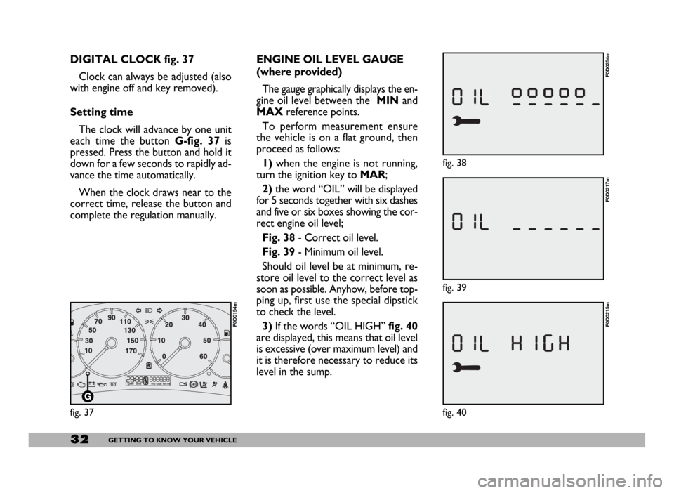
Fig. 38- Correct oil level.
Fig. 39- Minimum oil level.
Should oil level be at minimum, re-
store oil level to the correct level as
soon as possible. Anyhow, before top-
ping up, first use the special dipstick
to check the level.
3)If the words “OIL HIGH”fig. 40
are displayed, this means that oil level
is excessive (over maximum level) and
it is therefore necessary to reduce its
level in the sump. DIGITAL CLOCK fig. 37
Clock can always be adjusted (also
with engine off and key removed).
Setting time
The clock will advance by one unit
each time the button G-fig. 37is
pressed. Press the button and hold it
down for a few seconds to rapidly ad-
vance the time automatically.
When the clock draws near to the
correct time, release the button and
complete the regulation manually.
fig. 37
F0D0154m
fig. 38
F0D0254m
fig. 40
F0D0215m
Page 100 of 258
99GETTING TO KNOW YOUR VEHICLE
IMPORTANT The cables are se-
cured to the heater cables bundle with
adhesive tape to cut out noise.
For speakers, use the housings at the
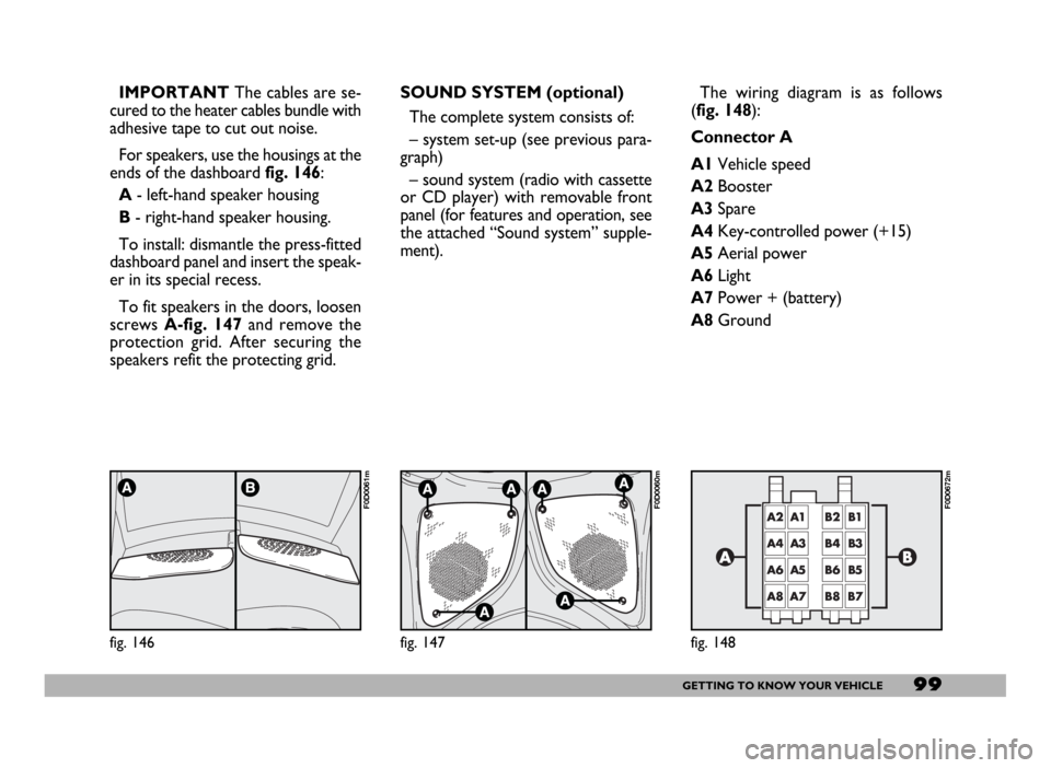
ends of the dashboard fig. 146:
A- left-hand speaker housing
B- right-hand speaker housing.
To install: dismantle the press-fitted
dashboard panel and insert the speak-
er in its special recess.
To fit speakers in the doors, loosen
screws A-fig. 147and remove the
protection grid. After securing the
speakers refit the protecting grid.
fig. 146
F0D0061m
SOUND SYSTEM (optional)
The complete system consists of:
– system set-up (see previous para-
graph)
– sound system (radio with cassette
or CD player) with removable front
panel (for features and operation, see
the attached “Sound system” supple-
ment).
fig. 147
F0D0060m
The wiring diagram is as follows
(fig. 148):
Connector A
A1Vehicle speed
A2Booster
A3Spare
A4Key-controlled power (+15)
A5Aerial power
A6Light
A7Power + (battery)
A8Ground
fig. 148
F0D0672m
Page 101 of 258
100GETTING TO KNOW YOUR VEHICLE
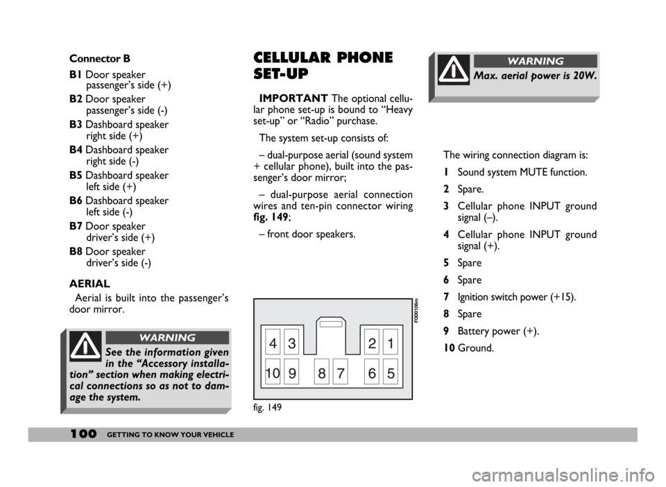
The wiring connection diagram is:
1Sound system MUTE function.
2Spare.
3Cellular phone INPUT ground
signal (–).
4Cellular phone INPUT ground
signal (+).
5Spare
6Spare
7Ignition switch power (+15).
8Spare
9Battery power (+).
10Ground.
Max. aerial power is 20W.
WARNINGConnector B
B1Door speaker
passenger’s side (+)
B2Door speaker
passenger’s side (-)
B3Dashboard speaker
right side (+)
B4Dashboard speaker
right side (-)
B5Dashboard speaker
left side (+)
B6Dashboard speaker
left side (-)
B7Door speaker
driver’s side (+)
B8Door speaker
driver’s side (-)
AERIAL
Aerial is built into the passenger’s
door mirror.CELLULAR PHONE
SET-UP
IMPORTANTThe optional cellu-
lar phone set-up is bound to “Heavy
set-up” or “Radio” purchase.
The system set-up consists of:
– dual-purpose aerial (sound system
+ cellular phone), built into the pas-
senger’s door mirror;
– dual-purpose aerial connection
wires and ten-pin connector wiring
fig. 149;
– front door speakers.
fig. 149
F0D0106m
See the information given
in the “Accessory installa-
tion” section when making electri-
cal connections so as not to dam-
age the system.
WARNING
Page 117 of 258
116GETTING THE BEST OUT OF YOUR VEHICLE
BUMP STARTING
Starting by pushing or towing the ve-
hicle is not possible. In the event of an
emergency, when the battery is flat,
start the vehicle with a suitable emer-
gency battery, following the instruc-
tions given in section “In an emer-
gency” at paragraph “Jump starting”.
TOWING THE VEHICLE
IMPORTANTFor towing the ve-
hicle comply with current local regu-
lations and follow the instructions giv-
en in section “In an emergency” at
paragraph “Towing the vehicle”.If the vehicle is to be towed, adhere
to the following recommendations:
– if possible, carry the vehicle on the
floor of a rescue vehicle;
– if this is not possible, tow the ve-
hicle raising the driving wheels (front)
from the ground;
– if this, too, is not possible, the ve-
hicle should not be towed for more
than 200 km at a speed of no more
than 50 km/h.
When towing, the gearshift lever
should be at N.
Do not start the engine
while the vehicle is being
towed.
The failure to comply
with these instructions
may cause serious dam-
age to the automatic gearbox.
When travelling with the
gearbox faulty, drive with
the utmost care in consideration of
the limited performance (in terms
of acceleration and speed) that the
vehicle can offer.
WARNING
When travelling with the
gearbox faulty, the revers-
ing gear lock might not be active:
absolutely never move the lever to
the R position with the vehicle on
the move.
WARNING– Warning light flashing= auto-
matic gearbox fault.
Warning light flashing at starting or
when travelling indicates a fault in the
automatic gearbox.
The automatic control system sets
an “emergency programme” engaging
the 3
rdgear.
Switching the engine off and then on
again, the self-test system could ex-
clude the fault and therefore turn off
the warning light. The failure is how-
ever stored and the automatic gear-
box shall be checked at a Fiat Deal-
ership.
Page 131 of 258
130GETTING THE BEST OUT OF YOUR VEHICLE
The electrical brake or other device
(electrical winch, etc.) must be pow-
ered directly from the battery by
means of a lead with a cross-section
area not smaller than 2.5 mm
2.
In addition to the electrical connec-
tions, only the power wire for an ad-
ditional electrical brake and for inter-
nal trailer lighting with a power not
exceeding 15W can be connected to
the vehicle’s electrical system.
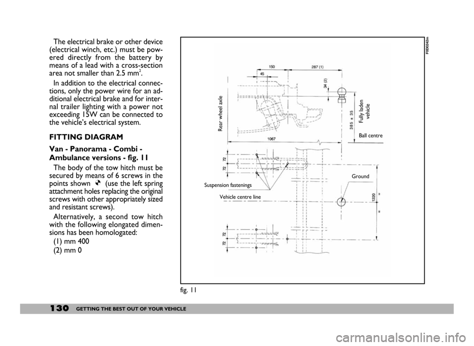
FITTING DIAGRAM
Van - Panorama - Combi -
Ambulance versions - fig. 11
The body of the tow hitch must be
secured by means of 6 screws in the
points shown Ø(use the left spring
attachment holes replacing the original
screws with other appropriately sized
and resistant screws).
Alternatively, a second tow hitch
with the following elongated dimen-
sions has been homologated:
(1) mm 400
(2) mm 0
fig. 11
F0D0242m
Rear wheel axle
Fully laden
vehicleBall centre
Suspension fastenings
Vehicle centre lineGround
Page 139 of 258
138IN AN EMERGENCY
1. STOP THE VEHICLE
– Stop the vehicle in a position that
is not dangerous for oncoming traffic
where you can change the wheel safe-
ly. The ground should be flat and ad-
equately firm. If you have to change
the wheel at night, choose a lit area if
possible.
– Turn the engine off and pull up the
handbrake.
– Engage first or reverse gear.
– Alert other drivers that the vehicle
is stationary in compliance with local
regulations: hazard warning lights,
warning triangle, etc.
Any passengers should get out and
wait as far away as possible from the
danger of traffic.
If the road is sloping or bumpy, place
wedges or other suitable material to
prevent the vehicle from moving, un-
der the wheels.2. TAKE OUT THE TOOLS,
JACK AND SPARE WHEEL
The tools are in the cab near the
seats.
Please note:
– the jack weights 4.2 kg;
– the jack requires no adjustments;
– the jack cannot be repaired. If it
breaks it must be replaced with a new
jack;
– no other tool, apart from the ex-
tension and the ratchet wrench shown
in this chapter can be fitted to the jack.
The spare wheel is located under the
rear part of the load bed.
Do not lubricate the bolt
threads before fitting
them back: they could come
loose.
WARNING
Check tyre pressure and
spare wheel pressure regu-
larly. Refer to section “Technical
Specifications”.
WARNING
Page 140 of 258
139IN AN EMERGENCY
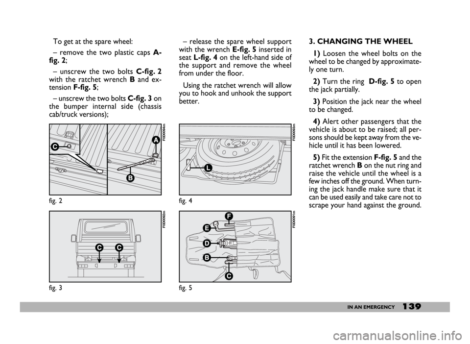
To get at the spare wheel:
– remove the two plastic caps A-
fig. 2;
– unscrew the two bolts C-fig. 2
with the ratchet wrench B and ex-
tension F-fig. 5;
– unscrew the two bolts C-fig. 3on
the bumper internal side (chassis
cab/truck versions);– release the spare wheel support
with the wrench E-fig. 5inserted in
seatL-fig. 4 on the left-hand side of
the support and remove the wheel
from under the floor.
Using the ratchet wrench will allow
you to hook and unhook the support
better.3. CHANGING THE WHEEL
1) Loosen the wheel bolts on the
wheel to be changed by approximate-
ly one turn.
2) Turn the ring D-fig. 5 to open
the jack partially.
3)Position the jack near the wheel
to be changed.
4) Alert other passengers that the
vehicle is about to be raised; all per-
sons should be kept away from the ve-
hicle until it has been lowered.
5)Fit the extension F-fig. 5and the
ratchet wrench Bon the nut ring and
raise the vehicle until the wheel is a
few inches off the ground. When turn-
ing the jack handle make sure that it
can be used easily and take care not to
scrape your hand against the ground.
fig. 2
F0D0094m
fig. 3
F0D0092m
fig. 4
F0D0093m
fig. 5
F0D0091m
Page 161 of 258
160IN AN EMERGENCY
IF AN ACCIDENT
OCCURS
– It is important to keep calm.
– If you are not directly involved in
the accident, stop at least ten metres
away from the accident.
– If you are on a motorway, do not
obstruct the emergency lane with
your vehicle.
– Turn the engine off and the haz-
ard lights on.
– At night, illuminate the scene of the
accident with your headlights.
– Act carefully, you must not risk be-
ing run over.
– Mark the accident by putting the
red triangle at the regulatory distance
from the vehicle where it can be clear-
ly see.
– If the doors are blocked, do not at-
tempt to smash the windscreen to get
out of the vehicle. It is made of layered
glass and is very hard. Side and rear
windows are much more easily bro-
ken. VEHICLE WITH AUTOMATIC
GEARBOX
If towing is not due to gearbox faults,
proceed as follows:
– gearshift lever to N;
– do not exceed 50 km/h;
– the vehicle should not be towed
for more than 200 km.
If towing is due to gearbox faults or
the vehicle should be towed for more
than 200 km, tow the vehicle raising
the front wheels from the ground.– Call for rescue making the infor-
mation you give as accurate as you
can.On the motorway use the special
column-mounted emergency phones.
– In pile-ups on the motorway, par-
ticularly when the visibility is bad,
there is a high risk of other vehicles
running into those already
stopped.Get out of the vehicle imme-
diately and take refuge behind the
guard rail.
– Remove the ignition keys from the
vehicles involved.
– If you can smell petrol or other
chemicals, do not smoke and make
sure all cigarettes are extinguished.
– Use a fire extinguisher, blanket, sand
or earth to put out fires no matter how
small they are. Never use water.
When towing the vehicle
you must comply with the
specific traffic regulations regard-
ing the tow hitch and how to tow
on the road.
WARNING
Page 170 of 258
169VEHICLE MAINTENANCE
Do not add oil with dif-
ferent specifications from
the oil already in the en-
gine.
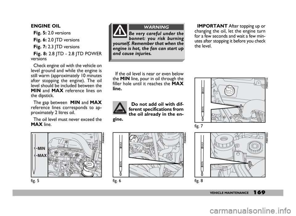
ENGINE OIL
Fig. 5:2.0 versions
Fig. 6:2.0 JTD versions
Fig. 7:2.3 JTD versions
Fig. 8: 2.8 JTD - 2.8 JTD POWER
versions
Check engine oil with the vehicle on
level ground and while the engine is
still warm (approximately 10 minutes
after stopping the engine). The oil
level should be included between the
MINand MAXreference lines on
the dipstick.
The gap between MINand MAX
reference lines corresponds to ap-
proximately 2 litres oil.
The oil level must never exceed the
MAXline.If the oil level is near or even below
the MINline, pour in oil through the
filler hole until it reaches the MAX
line.
fig. 5
F0D0063m
fig. 6
F0D0064m
fig. 7
F0D0211m
fig. 8
F0D0183m
Be very careful under the
bonnet: you risk burning
yourself. Remember that when the
engine is hot, the fan can start up
and cause injuries.
WARNINGIMPORTANT After topping up or
changing the oil, let the engine turn
for a few seconds and wait a few min-
utes after stopping it before you check
the level.