heater FIAT DUCATO 244 2005 3.G Owners Manual
[x] Cancel search | Manufacturer: FIAT, Model Year: 2005, Model line: DUCATO 244, Model: FIAT DUCATO 244 2005 3.GPages: 258, PDF Size: 4.05 MB
Page 55 of 258
54GETTING TO KNOW YOUR VEHICLE
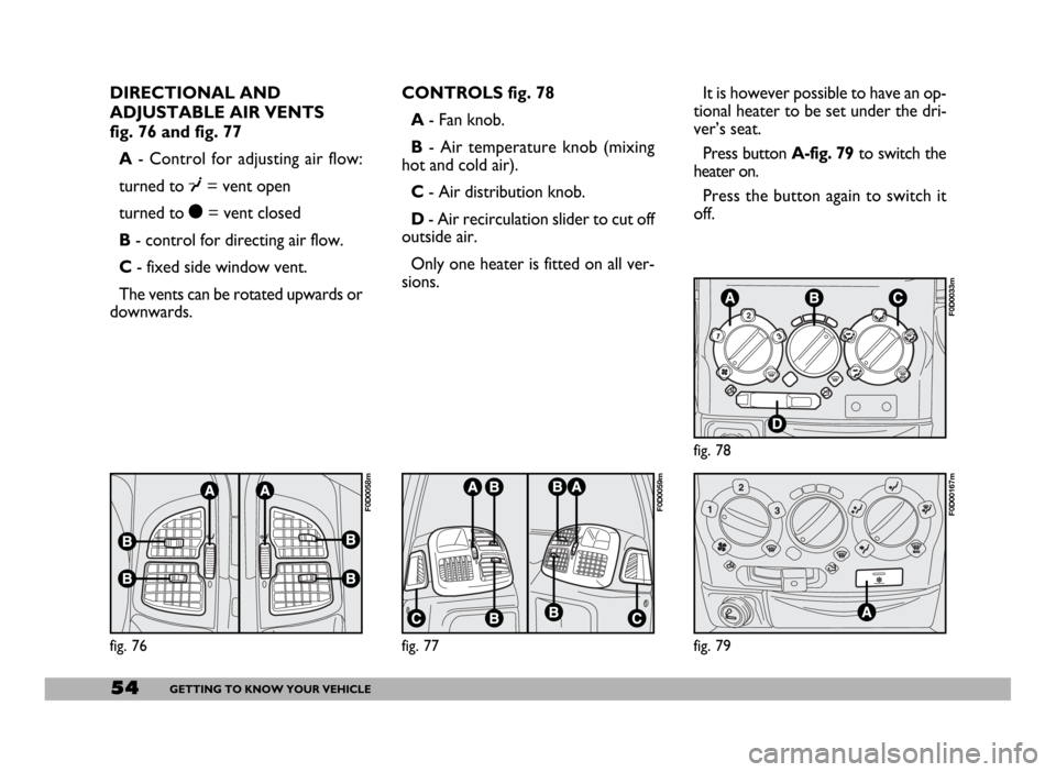
DIRECTIONAL AND
ADJUSTABLE AIR VENTS
fig. 76 and fig. 77
A- Control for adjusting air flow:
turned to ┬ź= vent open
turned to ├¦= vent closed
B- control for directing air flow.
C- fixed side window vent.
The vents can be rotated upwards or
downwards.CONTROLS fig. 78
A- Fan knob.
B- Air temperature knob (mixing
hot and cold air).
C- Air distribution knob.
D- Air recirculation slider to cut off
outside air.
Only one heater is fitted on all ver-
sions.It is however possible to have an op-
tional heater to be set under the dri-
verŌĆÖs seat.
Press button A-fig. 79to switch the
heater on.
Press the button again to switch it
off.
fig. 76
F0D0058m
fig. 77
F0D0059m
fig. 79
F0D00167m
fig. 78
F0D0033m
Page 56 of 258
55GETTING TO KNOW YOUR VEHICLE
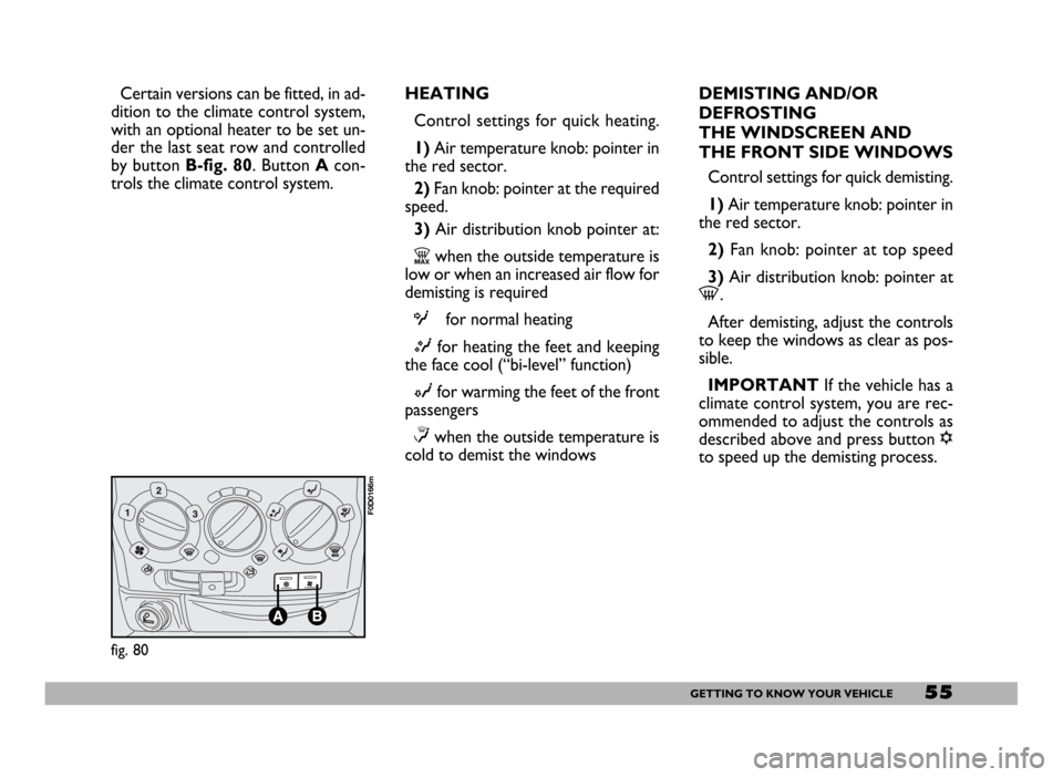
Certain versions can be fitted, in ad-
dition to the climate control system,
with an optional heater to be set un-
der the last seat row and controlled
by button B-fig. 80. Button Acon-
trols the climate control system.HEATING
Control settings for quick heating.
1)Air temperature knob: pointer in
the red sector.
2) Fan knob: pointer at the required
speed.
3) Air distribution knob pointer at:
Zwhen the outside temperature is
low or when an increased air flow for
demisting is required
Ofor normal heating
Mfor heating the feet and keeping
the face cool (ŌĆ£bi-levelŌĆØ function)
Nfor warming the feet of the front
passengers
Ōēżwhen the outside temperature is
cold to demist the windowsDEMISTING AND/OR
DEFROSTING
THE WINDSCREEN AND
THE FRONT SIDE WINDOWS
Control settings for quick demisting.
1) Air temperature knob: pointer in
the red sector.
2) Fan knob: pointer at top speed
3) Air distribution knob: pointer at
-.
After demisting, adjust the controls
to keep the windows as clear as pos-
sible.
IMPORTANT If the vehicle has a
climate control system, you are rec-
ommended to adjust the controls as
described above and press button ŌłÜ
to speed up the demisting process.
fig. 80
F0D0166m
Page 59 of 258
58GETTING TO KNOW YOUR VEHICLE
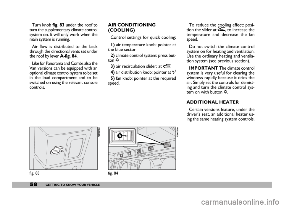
Turn knob fig. 83 under the roof to
turn the supplementary climate control
system on. It will only work when the
main system is running.
Air flow is distributed to the back
through the directional vents set under
the roof by lever A-fig. 84.
Like for Panorama and Combi, also the
Van versions can be equipped with an
optional climate control system to be set
in the load compartment and to be
switched on using the relevant console
controls.AIR CONDITIONING
(COOLING)
Control settings for quick cooling:
1)air temperature knob: pointer at
the blue sector
2)climate control system: press but-
ton ŌłÜ
3)air recirculation slider: at Ò
4) air distribution knob: pointer at O
5)fan knob: pointer at the required
speed.To reduce the cooling effect: posi-
tion the slider at Ú, to increase the
temperature and decrease the fan
speed.
Do not switch the climate control
system on for heating and ventilation.
Use the ordinary heating and ventila-
tion system (see previous section).
IMPORTANT The climate control
system is very useful for clearing the
windows rapidly because it dries the
air. Simply set the controls for demist-
ing and turn the climate control sys-
tem on with button ŌłÜ.
ADDITIONAL HEATER
Certain versions feature, under the
driverŌĆÖs seat, an additional heater us-
ing the same heating system controls.
fig. 83
F0D0049m
fig. 84
F0D0075m
Page 60 of 258
59GETTING TO KNOW YOUR VEHICLE
SELF-STANDING SUPPLEMENTARY
HEATER (where provided)
The vehicle can be equipped, upon re-
quest, with two different self-standing
heaters:one is totally automatic
whereas the other is programmable.
AUTOMATIC VERSION
The supplementary heater is totally in-
dependent from the engine.
This heater is switched on automat-
ically (if required) when turning the ig-
nition key to MAR. LOOKING AFTER THE
SYSTEM
During the winter, the climate con-
trol system must be turned on at least
once a month for about ten minutes.
Before summer, have the system
checked at a Fiat Dealership.PROGRAMMABLE VERSION
The supplementary heater is totally
independent from the engine and can
be used to:
ŌĆō heat the passenger compartment
when the engine is off;
ŌĆō defrost the windows;
ŌĆō heat the engine coolant and con-
sequently the engine before starting.
The system consists of:
ŌĆō a diesel burner to heat coolant with
exhaust fume muffler;
ŌĆō a metering pump connected to the
vehicle fuel pipes to feed the burner;
ŌĆō a heat exchanger connected to the
engine cooling system pipes; The system is filled with
R134a refrigerant which
will not pollute the envi-
ronment in the event of leakage.
Under no circumstances should
R12 fluid be used as it is incom-
patible with the system compo-
nents and contains CFC.
The heater burns fuel in the
same way as the engine,
though, of course, to a lesser degree
and therefore to avoid intoxication
and suffocation, never use the sup-
plementary heater in closed areas,
garages or workshops not equipped
with specific exhaust evacuation
devices even for short periods of
time.
WARNING
Page 61 of 258
60GETTING TO KNOW YOUR VEHICLE
ŌĆō a control unit connected to the
heater/ventilation unit for automatic
operation;
ŌĆō an electronic control unit to check
and adjusted the integrated heater
burner;
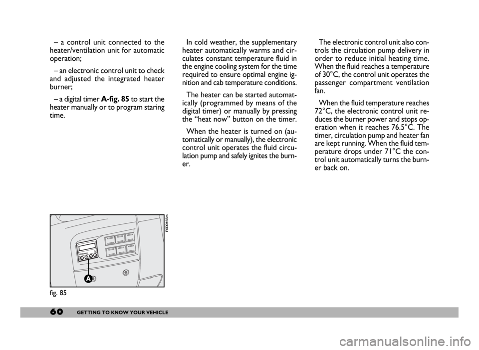
ŌĆō a digital timer A-fig. 85to start the
heater manually or to program staring
time.In cold weather, the supplementary
heater automatically warms and cir-
culates constant temperature fluid in
the engine cooling system for the time
required to ensure optimal engine ig-
nition and cab temperature conditions.
The heater can be started automat-
ically (programmed by means of the
digital timer) or manually by pressing
the ŌĆ£heat nowŌĆØ button on the timer.
When the heater is turned on (au-
tomatically or manually), the electronic
control unit operates the fluid circu-
lation pump and safely ignites the burn-
er.The electronic control unit also con-
trols the circulation pump delivery in
order to reduce initial heating time.
When the fluid reaches a temperature
of 30┬░C, the control unit operates the
passenger compartment ventilation
fan.
When the fluid temperature reaches
72┬░C, the electronic control unit re-
duces the burner power and stops op-
eration when it reaches 76.5┬░C. The
timer, circulation pump and heater fan
are kept running. When the fluid tem-
perature drops under 71┬░C the con-
trol unit automatically turns the burn-
er back on.
fig. 85
F0D0165m
Page 62 of 258
61GETTING TO KNOW YOUR VEHICLE
IMPORTANTThe heater is
equipped with a thermal switch which
cuts off the heater in the event of
overheating caused by low or leaking
coolant. In this case, press the pro-
gram selection button to start the
heater again after repairing the cool-
ing system fault and/or topping up the
fluid.
The heater can turn itself off after en-
gine ignition or if the flame goes out.
In this case, turn the heater off man-
ually and attempt to turn it back on
again. If you cannot turn the heater on,
contact a Fiat Dealership.Turning the heater on
Before turning the heater on check
that:
ŌĆō the heating/ventilation unit knob is
turned to ŌĆ£warm airŌĆØ;
ŌĆō the heating/ventilation fan speed
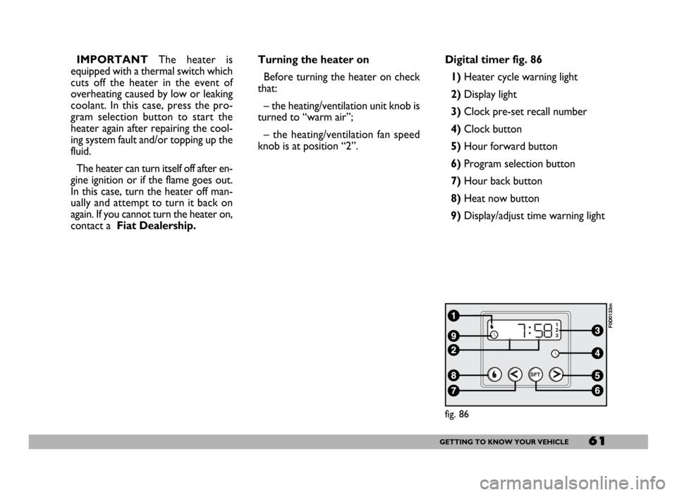
knob is at position ŌĆ£2ŌĆØ.Digital timer fig. 86
1) Heater cycle warning light
2)Display light
3)Clock pre-set recall number
4)Clock button
5)Hour forward button
6)Program selection button
7)Hour back button
8) Heat now button
9) Display/adjust time warning light
fig. 86
F0D0133m
Page 63 of 258
62GETTING TO KNOW YOUR VEHICLE
fig. 87
F0D0132m
fig. 88
F0D0134m
fig. 89
F0D0136m
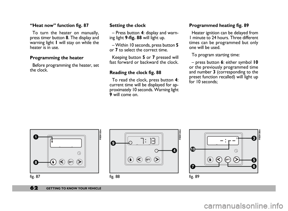
ŌĆ£Heat nowŌĆØ function fig. 87
To turn the heater on manually,
press timer button 8. The display and
warning light 1will stay on while the
heater is in use.
Programming the heater
Before programming the heater, set
the clock.Setting the clock
ŌĆō Press button 4: display and warn-
ing light 9-fig. 88will light up.
ŌĆō Within 10 seconds, press button 5
or 7to select the correct time.
Keeping button 5or 7pressed will
fast forward or backward the clock.
Reading the clock fig. 88
To read the clock, press button 4:
current time will be displayed for ap-
proximately 10 seconds. Warning light
9will come on.Programmed heating fig. 89
Heater ignition can be delayed from
1 minute to 24 hours. Three different
times can be programmed but only
one will be used.
To program starting time:
ŌĆō press button 6: either symbol 10
or the previously programmed time
and number 3 (corresponding to the
preset function recalled) will light up
for 10 seconds;
Page 64 of 258
63GETTING TO KNOW YOUR VEHICLE
IMPORTANTTo recall other pre-
set times, press button 6within 10
seconds.
ŌĆō press button 5or 7to select the
starting time required within 10 sec-
onds.
IMPORTANTStarting time disap-
pears and the number 3(correspond-
ing to the selected preset time) ap-
pears on the display to confirm the
starting time has been entered.
Deleting a programmed
starting time fig. 89
To delete the programmed starting
time, press button 6briefly: the dis-
play light will go off and number 3cor-
responding to the selected preset
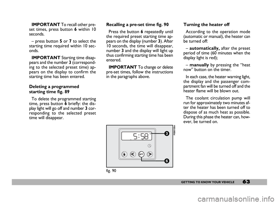
time will disappear.Recalling a pre-set time fig. 90
Press the button 6repeatedly until
the required preset starting time ap-
pears on the display (number 3). After
10 seconds, the time will disappear,
number 3and the display will light up
thus confirming starting time has been
entered.
IMPORTANTTo change or delete
pre-set times, follow the instructions
in the paragraphs above.Turning the heater off
According to the operation mode
(automatic or manual), the heater can
be turned off:
ŌĆōautomatically,after the preset
period of time (60 minutes when the
display light is red);
ŌĆō manuallyby pressing the ŌĆ£heat
nowŌĆØ button on the timer.
In each case, the heater warning light,
the display and the passenger com-
partment fan will be turned off and the
heater flame will be blown out.
The coolant circulation pump will
run for approximately two minutes af-
ter the heater has been turned off to
dispose of as much heat as possible.
During this phase the heater can, how-
ever, be turned on.
fig. 90
F0D0135m
Page 65 of 258
64GETTING TO KNOW YOUR VEHICLE
ŌĆō Always remember to turn the
heater off when refuelling or standing
in service stations to avoid fires and
explosions.
ŌĆō Do not park the vehicle over in-
flammable material such as paper, dry
grass or leaves: fire risk!
ŌĆō The temperature near the heater
must never exceed 120┬░C (e.g. during
painting operations in a workshop
oven). Higher temperatures could
damage the electronic control unit
components.
ŌĆō When the engine is off, the heater
runs off the battery: it is consequently
important to run the engine for a cer-
tain period of time in order to restore
the battery charge.ŌĆō Follow the prescriptions in ŌĆ£Vehi-
cle maintenanceŌĆØ section at paragraph
ŌĆ£Engine coolant levelŌĆØ to check the
coolant level. The coolant in the cir-
cuit must contain at least 10% an-
tifreeze fluid.
ŌĆō Maintenance and repairs must al-
ways be carried out by a Fiat Deal-
ershipand only genuine spare parts
must be used.
MAINTENANCE
Have the heater checked at a Fiat
Dealership periodically (always be-
fore winter). This will ensure safe and
cheap running and long appliance life.
The heater burns fuel in the
same way as the engine,
though, of course, to a lesser degree
and therefore to avoid intoxication
and suffocation, never use the sup-
plementary heater in closed areas,
garages or workshops not equipped
with specific exhaust evacuation
devices even for short periods of
time.
WARNING
Page 100 of 258
99GETTING TO KNOW YOUR VEHICLE
IMPORTANT The cables are se-
cured to the heater cables bundle with
adhesive tape to cut out noise.
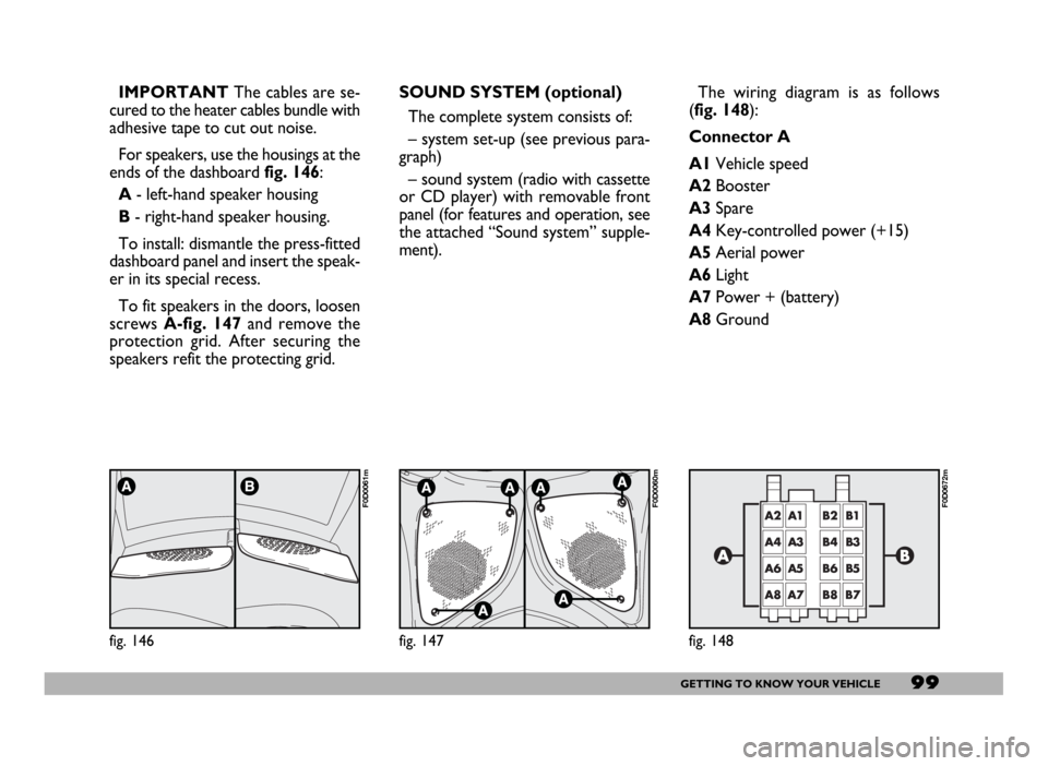
For speakers, use the housings at the
ends of the dashboard fig. 146:
A- left-hand speaker housing
B- right-hand speaker housing.
To install: dismantle the press-fitted
dashboard panel and insert the speak-
er in its special recess.
To fit speakers in the doors, loosen
screws A-fig. 147and remove the
protection grid. After securing the
speakers refit the protecting grid.
fig. 146
F0D0061m
SOUND SYSTEM (optional)
The complete system consists of:
ŌĆō system set-up (see previous para-
graph)
ŌĆō sound system (radio with cassette
or CD player) with removable front
panel (for features and operation, see
the attached ŌĆ£Sound systemŌĆØ supple-
ment).
fig. 147
F0D0060m
The wiring diagram is as follows
(fig. 148):
Connector A
A1Vehicle speed
A2Booster
A3Spare
A4Key-controlled power (+15)
A5Aerial power
A6Light
A7Power + (battery)
A8Ground
fig. 148
F0D0672m