Engine FIAT DUCATO BASE CAMPER 2014 Owner handbook (in English)
[x] Cancel search | Manufacturer: FIAT, Model Year: 2014, Model line: DUCATO BASE CAMPER, Model: FIAT DUCATO BASE CAMPER 2014Pages: 367, PDF Size: 20.39 MB
Page 41 of 367
IMPORTANT The engagement of the air
recirculation system makes it possible
to reach the required heating or cooling
conditions faster.
It is however inadvisable to use it on
rainy/cold days as it would considerably
increase the possibility of the windows
misting inside, especially if the climate
control compressor is off.
To prevent the windows from misting
up, the recirculation is forced off (i.e. air
is drawn in from the outside) when
the outside temperature is cold.
It is advisable not to use the air
recirculation function when the outside
temperature is low to prevent the
windows from rapidly misting up.
Climate control
compressor
enablement/off button
(F)
Press button
to switch the climate
control compressor off (if on). The icon
on the display will go out.
Press the button when the LED is off to
restore automatic system control of
compressor activation. The icon will
light up on the display.The system will switch recirculation off
when the compressor is switched off to
prevent windows from misting up.
Although the system is capable
of maintaining the required
temperature, the word FULL will
disappear from the display. If, on the
other hand, it is no longer capable
of maintaining the temperature, the
letters flash and the word AUTO goes
out.
IMPORTANT With the compressor off, it
is not possible to introduce air cooler
than ambient temperature into the
passenger compartment. Furthermore,
in certain conditions, the windows
could mist up rapidly because the air is
not dehumidified.
The system remembers that the
compressor has been switched off,
even after the engine has stopped.
To restore automatic compressor
control, press the
button again (in
this case, the system will only work as a
heater) or press the AUTO button.
With the compressor switched off, if the
outside temperature is higher than the
one set, the system is not capable
of satisfying this request. This is
signalled by the target temperature
flashing, after which the word AUTO
goes out.With the climate control compressor
off, the fan speed can be set to zero
manually (no bar shown).
With the compressor enabled and the
engine started, the fan speed may
be reduced to the minimum setting
(only one bar shown).
Button for rapid window
demisting/defrosting (D)
Press this button and the climate
control system will automatically switch
on all the functions required for fast
windscreen and side window
demisting/defrosting:
❒switches on climate control
compressor when climatic conditions
are suitable;
❒switches air recirculation off;
❒maximum air temperature HI in both
areas;
❒sets the fan speed according to the
engine coolant temperature to limit
the flow of air that is not sufficiently
warm to demist the windows;
❒directs air flow to windscreen and
front side windows vents;
❒heated rear window on.
37
Page 42 of 367
IMPORTANT The rapid demisting/
defrosting function for the windows
remains on for about 3 minutes from
when the engine coolant reaches the
appropriate temperature for a rapid
demisting of the windows.
When this function is active, the LED on
the corresponding button and the one
on the heated rear window button
switch on. The message FULL AUTO
goes off on the display.
You can only adjust the fan speed and
switch off the heated rear window
manually when this function is active.
To restore the previous operating
conditions, simply press button B, air
recirculation button G, compressor
button F or AUTO button A.
NoteTo guarantee rapid demisting/
defrosting, if an additional heater/air
conditioner is present (under the front
or rear seat on Panorama and Combi
versions), if activated, deactivate it
using button F (LED off) located
in control panel F fig. 55.Switching the system
OFF (E)
Press button E to switch the climate
control system off. The display will go
out.
The following climate control conditions
will be present when the system is off:
❒display off;
❒temperature setting not displayed;
❒air recirculation on, thereby insulating
the passenger compartment from the
outside (recirculation LED on);
❒climate control compressor off;
❒fan off.
Press the AUTO button to switch the
climate control system back on in
full automatic mode.
ADDITIONAL
HEATER(for versions/markets, where provided)
On some versions, an additional heater
is also present beneath the driver's
seat. The fan for this heater is operated
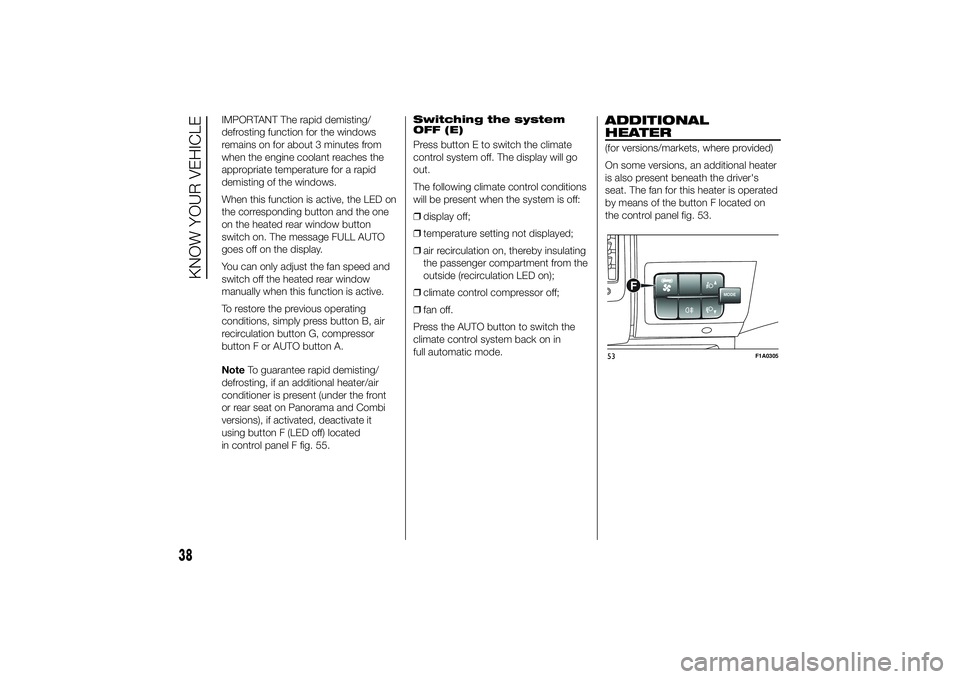
by means of the button F located on
the control panel fig. 53.
MODE
F
53
F1A0305
38
KNOW YOUR VEHICLE
Page 43 of 367
INDEPENDENT
ADDITIONAL
HEATER(for versions/markets, where provided)
The vehicle is available, on request,
with two different independent heaters:
one fully automatic, the other which
can be programmed.
AUTOMATIC VERSION
The additional heater is turned on in
automatic mode when the engine
is started and the required outside
temperature and coolant conditions are
present. Deactivation is always
automatic.
21)
IMPORTANT During periods with low
outdoor temperatures when the device
cuts in, check that the fuel level is
always higher than the reserve level.
Otherwise the device could lock and
require the assistance of a Fiat
Dealership.
PROGRAMMABLE
VERSION
The additional heater operates
completely independently of engine
operation and allows the following:❒heating the passenger compartment
with the engine off
❒defrosting the windows;
❒heat the engine coolant and then the
engine itself prior to starting.
The system consists of:
❒a diesel burner for heating the water
with an exhaust silencer for the
combustion gases;
❒a metering pump connected to the
reservoir pipes for supplying the
burner;
❒a heat exchanger connected to the
engine cooling system pipes;
❒a control unit connected to the
passenger compartment
heating/ventilation system to allow
automatic operation;
❒an electronic control unit for
controlling and adjusting the built-in
burner;
❒a digital timer fig. 54 for turning the
heater on manually or for
programming the time that it comes
on.The additional heater (during winter)
heats, maintains the temperature of and
circulates engine coolant for a set time
period in order to ensure optimum
engine and passenger compartment
conditions at engine start-up.
The heater can operate automatically
when programmed with a digital timer
or manually by pressing the 'immediate
heating' button on the timer.
After heater activation, whether
programmed or manually, the electronic
control unit operates the coolant pump
and turns on the burner in accordance
with pre-set, controlled procedures.
The circulation pump output is also
controlled by the electronic control unit
in order to minimise the initial heating
time.
When the system operates, the control
unit turns on the passenger
compartment heater unit fan at the
second speed.
The thermal power of the boiler is
regulated automatically by the
electronic control unit depending on the
temperature of the engine coolant.
39
Page 46 of 367
IMPORTANT The programmed
switching on time can be altered or
cancelled by following the instructions
given previously.
Operation duration
setting
Hold the button pressed. At the same
time press button 3 or 8.
The time and warning light 7 are
displayed.
Hold button 4 pressed again. At the
same time press button 3 or 8.
The preset activation duration is
displayed and warning light 9 or 2
flashes.
Set the activation duration with button
3or8.
The set activation duration is stored as
soon as the text in the display
disappears, or pressing button 4.
Switching the heating
system off
Deactivation of the system, depending
on the type of activation (automatic
or manual), may be:
❒automaticwhen the programmed
duration is over; when the set time
is over, the display switches off.❒manualpressing the “immediate
heating” button on the timer again
(flame button 6).
In both cases, the heating warning light,
the display lighting and the passenger
compartment heater fan go off and
burning stops.
The fluid circulation pump continues to
work for around two minutes to
dissipate as much heat as possible; the
heater can be turned back on during
this stage.
22)
IMPORTANT The parking heater goes
off when battery voltage is low to allow
the vehicle to be started.
IMPORTANT Before turning on the
device, ensure that the fuel level is
above the reserve. Otherwise the
device could lock and require
the assistance of a Fiat Dealership.
❒Always turn off the heater when
refuelling and near service stations to
avoid the risk of explosion or fire
hazards.
❒Do not park the vehicle on
inflammable material such as paper,
grass or dry leaves: fire hazard!❒The temperature near the heater
should not exceed 120°C (e.g. during
oven painting in a body shop). The
electronic control unit components
may be damaged at higher
temperatures.
❒Whilst the heater is operating with the
engine switched off, it absorbs
energy from the battery; the engine
should therefore be left running
for a while to make sure that the
battery is properly recharged.
❒To check the coolant level, follow the
instructions in the "Vehicle
maintenance" chapter, "Engine
coolant system fluid" paragraph. The
water in the heating circuit must
contain a minimum percentage of
10% antifreeze.
❒For maintenance and repairs, consult
only a Fiat Dealership and use only
original parts.
MAINTENANCE
Have the additional heater checked
regularly at a Fiat Dealership (and
always at the start of every winter). This
will guarantee safe and economic
operation of the heater as well as a long
duration.
42
KNOW YOUR VEHICLE
Page 47 of 367
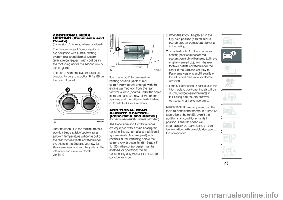
ADDITIONAL REAR
HEATING (Panorama and
Combi)
(for versions/markets, where provided)
The Panorama and Combi versions
are equipped with a main heating
system plus an additional system
(available on request) with controls in
the roof lining above the second row of
seats fig. 55.
In order to work the system must be
enabled through the button F fig. 56 on
the control panel.
Turn the knob D to the maximum cold
position (knob at blue sector); air at
ambient temperature will come out of
the rear footwell vents (located under
the seats in the 2nd and 3rd row for
Panorama versions and the grille on the
left wheel arch side for Combi
versions);Turn the knob D to the maximum
heating position (knob at red
sector);warm air will emerge (with the
engine warmed up), from the rear
footwell outlets (located under the seats
in the 2nd and 3rd row for Panorama
versions and the grille on the left wheel
arch side for Combi versions).
ADDITIONAL REAR
CLIMATE CONTROL
(Panorama and Combi)
(for versions/markets, where provided)
The Panorama and Combi versions
are equipped with a main heating/air
conditioning system plus an additional
system (available on request) with
controls in the roof lining above the
second row of seats fig. 55. Button F
fig. 56 in the control panel must be
enabled for operation; the air
conditioning only works if the main air
conditioner is on.❒When the knob D is placed in the
fully cold position (control in blue
sector) cold air comes out the vents
in the ceiling.
❒Turn the knob D to the maximum
heating position (knob at red
sector);warm air will emerge (with the
engine warmed up), from the rear
footwell outlets (located under the
seats in the 2nd and 3rd row for
Panorama versions and the grille on
the left wheel arch side for Combi
versions).
❒If the selector knob D is placed in the
intermediate positions, the air will be
distributed between the vents in
the ceiling and the rear footwell
vents, varying the temperature.
IMPORTANT If the compressor on the
main air conditioner control is turned on
(operation of button E), even if the
additional air conditioner fan is in
position 0, the 1st speed will
automatically be activated to prevent
ice formation, with possible damage to
the component.55
F1A0062
MODE
F
56
F1A0305
43
Page 48 of 367
WARNING
21) The heater burns fuel in the
same way as the engine, though
to a lesser extent. To prevent
poisoning and asphyxiation, the
additional heater must never
be turned on, not even for short
periods, in closed environments
such as a garage or workshops
without extraction fans for the
exhaust gases.
22) The heater burns fuel in the
same way as the engine, though
to a lesser extent. To prevent
poisoning and asphyxiation, the
supplementary heater must never
be turned on, not even for short
periods, in closed environments
such as a garage or workshops
without extraction fans for the
exhaust gases.
EXTERNAL LIGHTS
IN BRIEF
The left stalk includes the controls for
the exterior lights.
The exterior lights can only be
switched on when the ignition key is
in the ON position.
LIGHTS OFF
Ring nut turned to positionOfig. 57.DAYTIME RUNNING
LIGHTS (DRL)
(for versions/markets, where provided)
With the ignition key turned to MAR-ON
and the ring nut turned to positionO
fig. 57 the daytime running lights are
automatically activated; the other lights
and interior lighting remain off. The
automatic operation of the daytime
running lights can be activated/
deactivated, for versions/markets
where provided, via the display menu
(see "Display" in the "Knowing the
instrument panel" chapter).
If the daytime running lights are
deactivated, no light comes on when
the ring nut is turned toO.
23)
DIPPED BEAM
HEADLIGHTS/SIDE
LIGHTS
With the ignition key turned to
MAR-ON, turn the ring nut to
fig.
58.
If dipped headlights are activated, the
daytime running lights switch off and
the side lights and dipped headlights
switch on.
The
warning light switches on in
the instrument panel.
57
F1A0064
44
KNOW YOUR VEHICLE
Page 50 of 367
If the stalk is pulled again in this
condition, to request main beam
headlight deactivation, the function
remains off and the main beam
headlights switch off.
Rotate the ring nut to the position
fig. 58 to deactivate the automatic
function.25) 24)
PARKING LIGHTS
These lights can only be turned on with
ignition key in STOP position or
removed, by moving the left stalk ring
nut first to positionOand then to
position
or
.
The
warning light switches on in
the instrument panel.
DIRECTION INDICATORS
Bring the stalk into (stable) position fig.
61:
❒up (position 1): to activate the right
direction indicator;
❒down (position 2): to activate the left
direction indicator.
Warning light
or
will blink on the
instrument panel.
Direction indicators switch off
automatically when the vehicle is back
in a straight line.Lane change function
If you wish to signal a lane change,
place the left stalk in the unstable
position for less than half a second. The
direction indicator on the side selected
will flash five times and then switch
off automatically.
“FOLLOW ME HOME”
DEVICE
This device allows the illumination of the
space in front of the vehicle for a preset
time.
Activation
With ignition key at OFF or removed,
pull the stalk towards the steering
wheel fig. 62 and move it within
2 minutes after the engine stops.Each time the stalk is moved, the lights
stay on for an extra 30 seconds up to
a maximum of 210 seconds; then
the lights are switched off automatically.
The warning light
on the
instrument panel will light up and the
corresponding message will appear in
the display (see “Warning lights and
messages” section) for as long as the
function is activated.
The warning light comes on when the
stalk is operated and stays on until
the function is automatically
deactivated.
Each movement of the stalk only
increases the amount of time the lights
stay on.
61
F1A0068
62
F1A0069
46
KNOW YOUR VEHICLE
Page 55 of 367
Each activation of the lever
corresponds to an increase in speed of
about 1 km/h, whilst keeping the lever
upwards varies the speed continuously.
Reducing the stored
speed
This can be done in two ways:
❒by switching off the device and then
storing the new speed;
or
❒by moving the stalk downwards (-)
until the new speed, which will be
stored automatically, is reached.
Each movement of the lever will
correspond to a slight reduction in
speed of about 1 km/h, while keeping
the lever held downwards will decrease
the speed continuously.
Deactivating the device
The device can be switched off by
the driver in the following ways:
❒turning ring nut A to OFF orO
(according to the version);
❒by stopping the engine;Deactivating the
function
The device can be switched off by the
driver in the following ways:
❒turning ring nut A to OFF orO
(according to the version);
❒pressing the button B, both with
symbolIIand symbol CANC/RES,
the system pauses;
❒by stopping the engine;
❒by pressing the brake pedal or
operating the handbrake;
❒by pressing the clutch pedal;
❒requesting a gear shift with an
automatic transmission in sequential
mode;
❒with the vehicle speed below the set
limit
❒by pressing the accelerator pedal; in
this case the system is not actually
turned off but the acceleration
request takes priority; the Cruise
Control remains activated, without
the need to press the CANC/RES
button to restore the previous
conditions once the acceleration is
over.
The device is automatically switched off
in the following cases:
❒if the ABS or ESP systems cut in;❒in the event of system failure.
27) 28)
SPEED LIMITER
This device allows the speed of the car
to be limited to values which can be
set by the driver.
The maximum speed can be set both
with vehicle stationary and in motion.
The minimum speed that can be set is
30 km/h.
When the device is active, the car
speed depends on the pressure at the
accelerator pedal, until the
programmed speed limit is reached
(see "Speed limit programming"
paragraph).
If necessary (in the event of overtaking
for example), the set speed limit can
be exceeded by fully depressing the
accelerator pedal.
By gradually reducing the pressure on
the accelerator pedal, the function
will be reactivated as soon as the car
speed drops below the set speed.
51
Page 57 of 367
Deactivating the device
To deactivate the device, turn ring nut A
toO.
The deactivation of the device is
indicated by the
warning light
switching off on the instrument panel
and, on some versions, by a message
and
symbol on the display.
Automatic deactivation
of device
The device deactivates automatically in
the event of fault in the system.
WARNING
27) When travelling with the device
active, never move the gear lever
to neutral.
28) If the device is faulty, turn ring
nutAtoO, check the condition
of the fuse and contact a Fiat
Dealership.
ROOF LIGHTSFRONT ROOF LIGHT WITH
SPOT LIGHTS
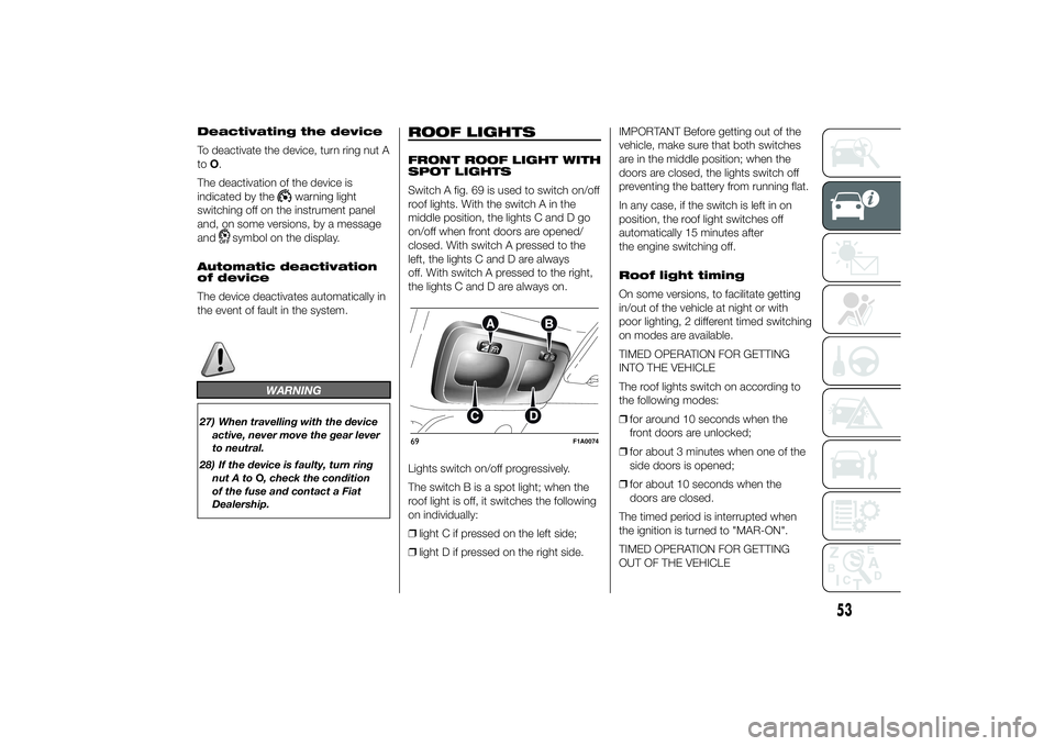
Switch A fig. 69 is used to switch on/off
roof lights. With the switch A in the
middle position, the lights C and D go
on/off when front doors are opened/
closed. With switch A pressed to the
left, the lights C and D are always
off. With switch A pressed to the right,
the lights C and D are always on.
Lights switch on/off progressively.
The switch B is a spot light; when the
roof light is off, it switches the following
on individually:
❒light C if pressed on the left side;
❒light D if pressed on the right side.IMPORTANT Before getting out of the
vehicle, make sure that both switches
are in the middle position; when the
doors are closed, the lights switch off
preventing the battery from running flat.
In any case, if the switch is left in on
position, the roof light switches off
automatically 15 minutes after
the engine switching off.
Roof light timing
On some versions, to facilitate getting
in/out of the vehicle at night or with
poor lighting, 2 different timed switching
on modes are available.
TIMED OPERATION FOR GETTING
INTO THE VEHICLE
The roof lights switch on according to
the following modes:
❒for around 10 seconds when the
front doors are unlocked;
❒for about 3 minutes when one of the
side doors is opened;
❒for about 10 seconds when the
doors are closed.
The timed period is interrupted when
the ignition is turned to "MAR-ON".
TIMED OPERATION FOR GETTING
OUT OF THE VEHICLE69
F1A0074
53
Page 58 of 367
After removing the key from the ignition,
the roof lights switch on according to
the following modes:
❒within 2 minutes of the engine being
switched off for a period of around
10 seconds;
❒when one of the side doors is
opened for a period of around
3 minutes;
❒when one of the doors is closed for a
period of about 10 seconds.
The timed period ends automatically
when the doors are locked.
LOAD COMPARTMENT
REAR COURTESY LIGHT
This is located above the rear door.
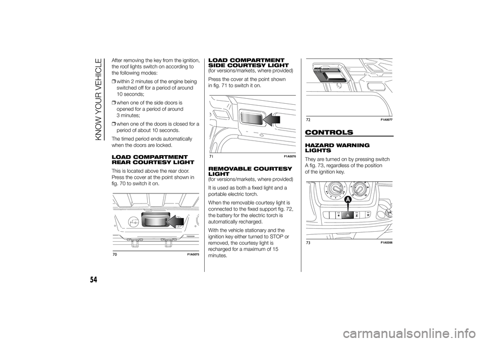
Press the cover at the point shown in
fig. 70 to switch it on.LOAD COMPARTMENT
SIDE COURTESY LIGHT
(for versions/markets, where provided)
Press the cover at the point shown
in fig. 71 to switch it on.
REMOVABLE COURTESY
LIGHT
(for versions/markets, where provided)
It is used as both a fixed light and a
portable electric torch.
When the removable courtesy light is
connected to the fixed support fig. 72,
the battery for the electric torch is
automatically recharged.
With the vehicle stationary and the
ignition key either turned to STOP or
removed, the courtesy light is
recharged for a maximum of 15
minutes.
CONTROLSHAZARD WARNING
LIGHTS
They are turned on by pressing switch
A fig. 73, regardless of the position
of the ignition key.
70
F1A0075
71
F1A0076
72
F1A0077
73
F1A0306
54
KNOW YOUR VEHICLE