key FIAT DUCATO BASE CAMPER 2014 Owner handbook (in English)
[x] Cancel search | Manufacturer: FIAT, Model Year: 2014, Model line: DUCATO BASE CAMPER, Model: FIAT DUCATO BASE CAMPER 2014Pages: 367, PDF Size: 20.39 MB
Page 176 of 367
PARKINGProceed as follows:
❒stop the engine and engage the
handbrake;
❒engage a gear (on a slope, engage
first gear if the car is facing uphill or
reverse if it is facing downhill) and
leave the wheels steered.
If the vehicle is parked on a steep
slope, it is advisable to block the
wheels with a wedge or stone.
Do not leave the key in the ignition as
this drains the battery. Always remove
the key when you leave the car.
126)
HANDBRAKE
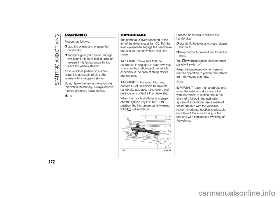
The handbrake lever is located to the
left of the driver's seat fig. 170. Pull the
lever upwards to engage the handbrake
and ensure that the vehicle does not
move.
IMPORTANT Make sure that the
handbrake is engaged in such a way as
to ensure the stationing of the vehicle,
especially in the case of steep slopes
and full load.
IMPORTANT If this is not the case,
contact a Fiat Dealership to have the
handbrake adjusted. If the lever travel
gets longer, contact a Fiat Dealership.
When the handbrake lever is engaged
and the ignition key is in MAR-ON
position, the instrument panel warning
light
will switch on.Proceed as follows to release the
handbrake:
❒slightly lift the lever and press release
button A;
❒keep button A pressed and lower the
lever.
The
warning light in the instrument
panel will switch off.
Press the brake pedal when carrying
out this operation to prevent the vehicle
from moving accidentally.
33)
IMPORTANT Apply the handbrake only
when the vehicle is at a standstill or
with the vehicle in motion only in the
event of a failure in the hydraulic
system. If exceptional use is made of
the handbrake with the vehicle in
motion, moderate traction is advisable
in order not to cause locking of the
rear end with consequent swerving of
the vehicle.
170
F1A0162
172
STARTING AND DRIVING
Page 177 of 367
WARNING
126) Never leave children
unattended in the vehicle. Always
remove the ignition key when
leaving the vehicle and take it out
with you.
IMPORTANT
33) If the vehicle is equipped with
self-levelling air suspension,
always check that there is
sufficient space above the roof
and around the vehicle when
parking. Indeed, the vehicle could
raise (or lower) automatically
depending on load or temperature
changes.
USING THE
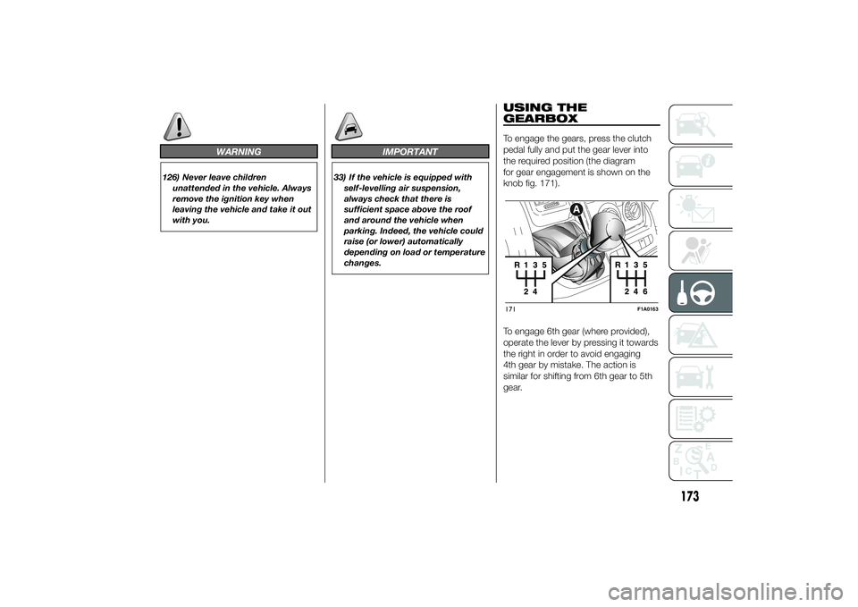
GEARBOXTo engage the gears, press the clutch
pedal fully and put the gear lever into
the required position (the diagram
for gear engagement is shown on the
knob fig. 171).
To engage 6th gear (where provided),
operate the lever by pressing it towards
the right in order to avoid engaging
4th gear by mistake. The action is
similar for shifting from 6th gear to 5th
gear.171
F1A0163
173
Page 187 of 367
INSTRUCTIONS FOR
USING THE REMOVABLE
BALL HEAD TOW BAR
36) 37) 38) 39) 40) 41)
Before setting off, check the correct
locking of the removable ball head tow
bar, as follows:
❒The green mark of the flywheel must
coincide with the green mark on the
tow bar.
❒The flywheel is in the stop position on
the tow bar (without slot).
❒Locked lock and key removed. The
flywheel cannot be removed.
❒Ball head bar firmly secured to the
housing pipe. Check by shaking
with a hand.
The fitting procedure must be repeated
if any of the 4 checked requirements
is not met.
If even only one of the requirements is
not met the tow hook must not be
used, as in this case there is risk of
accidents. Contact the joint
manufacturer.The ball head tow bar can be fitted and
removed manually, without needing
any tool.
Never use working tools or means, as
the mechanism could be damaged.
Never unlock in the case of trailer
attached to the vehicle or fitted rack.
When driving without trailer or rack the
ball head tow bar must be removed
and the closing plug must always
be inserted in the housing pipe. This
applies particularly if the visibility of the
number plate characters or of the
lighting system is reduced.Removable ball head
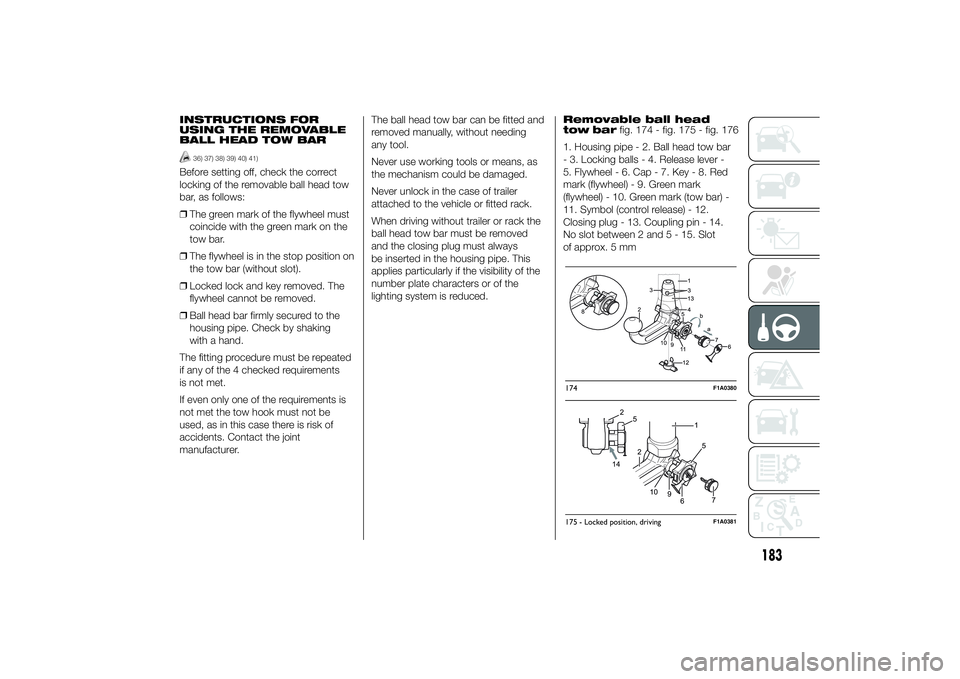
tow barfig. 174 - fig. 175 - fig. 176
1. Housing pipe - 2. Ball head tow bar
- 3. Locking balls - 4. Release lever -
5. Flywheel - 6. Cap - 7. Key - 8. Red
mark (flywheel) - 9. Green mark
(flywheel) - 10. Green mark (tow bar) -
11. Symbol (control release) - 12.
Closing plug - 13. Coupling pin - 14.
No slot between 2 and 5 - 15. Slot
of approx. 5 mm
174
F1A0380
175 - Locked position, driving
F1A0381
183
Page 188 of 367
Installing the ball head
tow bar
1. Remove the plug from the mounting
pipe.
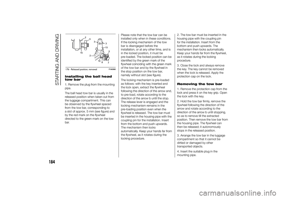
The ball head tow bar is usually in the
released position when taken out from
the luggage compartment. This can
be observed by the flywheel spaced
from the tow bar, corresponding to
a slot of approx. 5 mm (see figure) and
by the red mark on the flywheel
directed to the green mark on the tow
bar.Please note that the tow bar can be
installed only when in these conditions.
If the locking mechanism of the tow
bar is disengaged before the
installation, or at any other time, and is
in the locked position, it must be
pre-loaded. The locked position can be
identified by the green mark of the
flywheel coinciding with the green mark
of the tow bar and by the flywheel in
the stop position on the tow bar,
namely without slot (see figure).
The locking mechanism is pre-loaded
as follows: with the key inserted and
the lock open, extract the flywheel
following the direction of the arrow and,
to pre-load, rotate according to the
direction of the arrow b until the stop.
The release lever is engaged and the
locking mechanism remains in the
pre-loading position even when the
flywheel is released. The tow bar must
be inserted in the housing pipe with the
coupling pin for the installation. Insert
from the bottom and push upwards.
The mechanism then locks
automatically. Keep your hands far from
the flywheel, as it rotates during the
locking procedure.2. The tow bar must be inserted in the
housing pipe with the coupling pin
for the installation. Insert from the
bottom and push upwards. The
mechanism then locks automatically.
Keep your hands far from the flywheel,
as it rotates during the locking
procedure.
3. Close the lock and always remove
the key. The key cannot be removed
when the lock is released. Apply the
protection cap on the lock.
Removing the tow bar
1. Remove the protection cap from the
lock and press it on the key grip. Open
the lock with the key.
2. Hold the tow bar firmly, remove the
flywheel following the direction of the
arrow and rotate according to the
direction of the arrow b until stopping,
so as to remove till the extracted
position. Then remove the tow bar from
the housing pipe. The flywheel can
then be released; it autonomously
stops in the released position.
3. Arrange the tow bar in the luggage
compartment so that it cannot be
dirtied or damaged by other
transported objects.
4. Insert the suitable plug in the
mounting pipe.176 - Released position, removed
F1A0382
184
STARTING AND DRIVING
Page 189 of 367
IMPORTANT
36) The removable ball head bar can
be repaired and disassembled by
the manufacturer only.
37) The supplied plate must be
applied in a visible point on the
vehicle, close to the mounting
pipe or inside the luggage
compartment.
38) Regularly remove all dirt
deposits from the ball head bar
and from the mounting pipe to
ensure a correct system
operation. The mechanical
components must be serviced at
the specified intervals. The lock
must be treated with graphite
only.
39) Periodically lubricate the joints,
the sliding surfaces and the balls
with grease without resin or oil.
Lubrication is also a further
corrosion protection.
40) When the vehicle is cleaned with
high-pressure jets, previously
remove the ball head bar and
insert the suitable plug. The ball
head plug must never be treated
with high-pressure jets.41) Two keys are supplied together
with the removable ball tow bar.
Note down the key number on the
pawl for any following order and
keep it.
185
Page 192 of 367
❒cover the vehicle with a piece of
fabric or perforated plastic sheet. Do
not use compact plastic tarpaulins,
which prevent humidity from
evaporating from the surface of the
vehicle;
❒inflate tyres to +0.5 bar above the
standard specified pressure and
check it at intervals;
❒do not drain the engine cooling
system.
IMPORTANT If the vehicle is equipped
with an alarm system, switch off the
vehicle alarm with the remote control.
IMPORTANT After turning the ignition
key to STOP and having closed the
driver side door, wait at least one
minute before disconnecting the
electrical supply from the battery. When
reconnecting the electrical supply to
the battery, make sure that the ignition
key is in the STOP position and the
driver side door is closed.
188
STARTING AND DRIVING
Page 199 of 367
138) The spare wheel supplied (for
versions/markets, where
provided) is specific for your
vehicle. Therefore, it must not be
used on other models. Do not
use spare wheels of other models
on your vehicle. The wheel bolts
are specific for your vehicle: do
not use them on different models
and do not use bolts from other
models on your car.
139) Have the wheel repaired and
refitted as soon as possible. Do
not apply grease to the bolt
threads before fitting: they could
come unscrewed.
140) Use the jack only to replace
wheels on the vehicle with which
it is supplied or on other vehicles
of the same model. Never use
the jack for other purposes, such
as lifting other car models. Never
use the jack to carry out repairs
under the vehicle. Incorrect
positioning of the jack may cause
the lifted vehicle to fall. Do not
use the jack for loads higher than
those shown on the label.
141) Never tamper with the inflation
valve. Never introduce tools of any
kind between rim and tyre. Check
tyre and spare wheel pressure
regularly, referring to the values
shown in the "Technical
specifications" section.142) No tools other than the crank
provided should be used with
the spare wheel lifting device; it
should be operated by hand only.
143) On versions equipped with
self-levelling air suspension, never
introduce the head or hands in
the wheel arch: the vehicle could
raise or lower automatically
depending on possible load or
temperature changes.
144) The device should only be
operated by hand, without using
any type of tool other than the
crank provided, like pneumatic or
electrical screwers.
145) The moving components of the
jack (screw and joints) can also
cause injuries: do not touch them.
If you come into contact with
lubricating grease, clean yourself
thoroughly.146) At the end of the operation of
raising/locking the spare wheel,
after having checked the correct
positioning of the wheel under the
platform (white notch inside the
window on the device), the key
must be extracted, taking care not
to turn it in the wrong direction
to facilitate the extraction of the
key itself, to prevent the
attachment device from being
released and the wheel assembly
not being securely retained fig.
188.
147) Each time the spare wheel is
moved, check that it is correctly
positioned in its housing under
the platform. If it is not correctly
positioned, this could adversely
affect safety.
195
Page 218 of 367
Right central pillar optional fuse
box
(for versions/markets, where provided)
To gain access to the fuse box fig.
229, remove the protective cover fig.
228.
IMPORTANT
45) Never replace a blown fuse with
metal wires or other material.
WARNING
160) Never replace a fuse with
another with a higher amp rating;
DANGER OF FIRE. If a general
protection fuse (MEGA-FUSE,
MIDI-FUSE) is activated, contact a
Fiat Dealership.161) Before replacing a fuse, make
sure that the ignition key has
been removed and that all the
other services are switched off
and/or disengaged.
162) If the replaced fuse blows
again, contact a Fiat Dealership.
163) If a general protection fuse for
safety systems (airbag system,
braking system), power unit
systems (engine system,
transmission system) or steering
system blows, contact a Fiat
Dealership.
228
F1A0217
229
F1A0218
214
IN AN EMERGENCY
Page 219 of 367
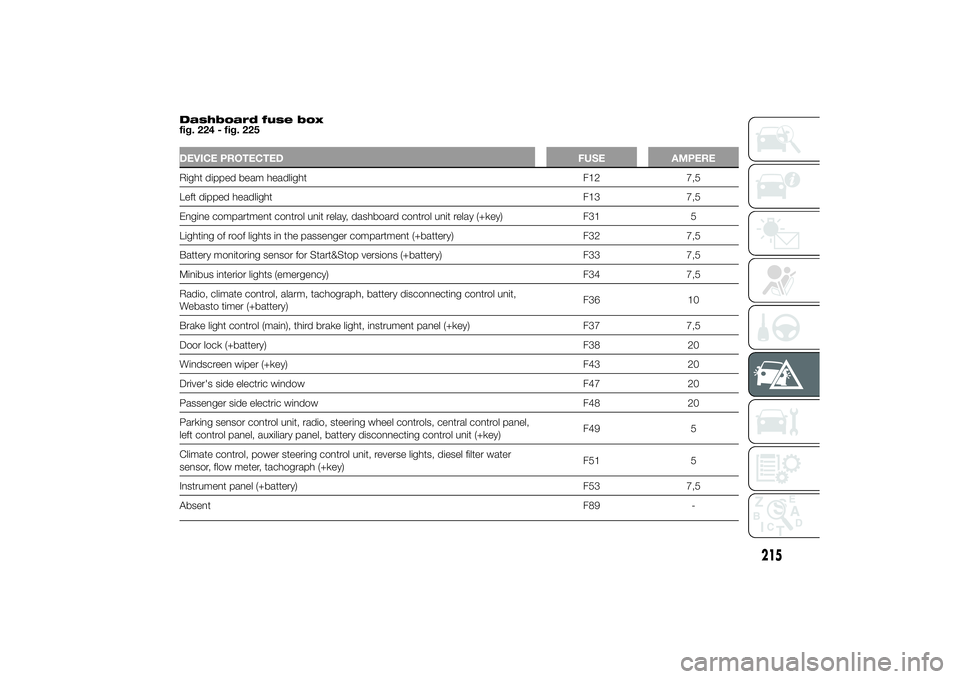
Dashboard fuse box
fig. 224 - fig. 225DEVICE PROTECTED FUSE AMPERERight dipped beam headlight F12 7,5
Left dipped headlight F13 7,5
Engine compartment control unit relay, dashboard control unit relay (+key) F31 5
Lighting of roof lights in the passenger compartment (+battery) F32 7,5
Battery monitoring sensor for Start&Stop versions (+battery) F33 7,5
Minibus interior lights (emergency) F34 7,5
Radio, climate control, alarm, tachograph, battery disconnecting control unit,
Webasto timer (+battery)F36 10
Brake light control (main), third brake light, instrument panel (+key) F37 7,5
Door lock (+battery) F38 20
Windscreen wiper (+key) F43 20
Driver's side electric window F47 20
Passenger side electric window F48 20
Parking sensor control unit, radio, steering wheel controls, central control panel,
left control panel, auxiliary panel, battery disconnecting control unit (+key)F49 5
Climate control, power steering control unit, reverse lights, diesel filter water
sensor, flow meter, tachograph (+key)F51 5
Instrument panel (+battery) F53 7,5
AbsentF89 -
215
Page 221 of 367
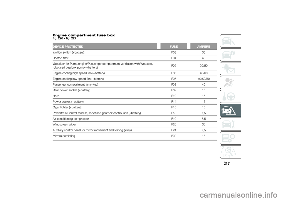
Engine compartment fuse box
fig. 226 - fig. 227DEVICE PROTECTED FUSE AMPEREIgnition switch (+battery) F03 30
Heated filterF04 40
Vaporiser for Puma engine/Passenger compartment ventilation with Webasto,
robotised gearbox pump (+battery)F05 20/50
Engine cooling high speed fan (+battery) F06 40/60
Engine cooling low speed fan (+battery) F07 40/50/60
Passenger compartment fan (+key) F08 40
Rear power socket (+battery) F09 15
HornF10 15
Power socket (+battery) F14 15
Cigar lighter (+battery) F15 15
Powertrain Control Module, robotised gearbox control unit (+battery) F18 7,5
Air conditioning compressor F19 7,5
Windscreen wiper F20 30
Auxiliary control panel for mirror movement and folding (+key) F24 7,5
Mirrors demisting F30 15
217