check engine FIAT DUCATO BASE CAMPER 2014 Owner handbook (in English)
[x] Cancel search | Manufacturer: FIAT, Model Year: 2014, Model line: DUCATO BASE CAMPER, Model: FIAT DUCATO BASE CAMPER 2014Pages: 367, PDF Size: 20.39 MB
Page 6 of 367
READ THIS CAREFULLYREFUELLING
Only refuel with automotive diesel conforming to the European specification EN590. The use of other products or mixtures may damage the
engine beyond repair and consequently invalidate the warranty, due to the damage caused.
STARTING THE ENGINE
Make sure that the handbrake is engaged; set the gear lever to neutral; fully depress the clutch pedal without pressing the accelerator, then
turn the ignition key to MAR-ON and wait for the warning lights
and
to switch off; turn the ignition key to AVV and release it as
soon as the engine has started.
PARKING ON FLAMMABLE MATERIAL
The catalytic converter develops high temperatures during operation. Do not park on grass, dry leaves, pine needles or other flammable
material: fire hazard.
RESPECTING THE ENVIRONMENT
The vehicle is fitted with a system that allows continuous diagnosis of the emission-related components in order to help protect the
environment.
ELECTRICAL ACCESSORIES
If, after buying the vehicle, you decide to add electrical accessories (with the risk of gradually draining the battery), visit a Fiat Dealership. They
can calculate the overall electrical requirement and check that the vehicle's electrical system can support the required load.
SCHEDULED SERVICING
Correct maintenance enables the vehicle to perfectly maintain performance and safety characteristics, its environmental friendliness and low
running costs over time.
THE OWNER HANDBOOK CONTAINS
... important information, advice and warnings for correct use, driving safety and maintenance of your vehicle over time. Special attention
must be paid to the symbols
(safety of persons)
(environmental protection)
(vehicle integrity).
Page 9 of 367
GRAPHICAL INDEX
.
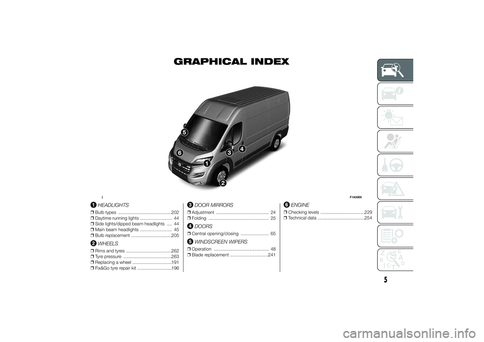
HEADLIGHTS
❒Bulb types ..........................................202
❒Daytime running lights ......................... 44
❒Side lights/dipped beam headlights .... 44
❒Main beam headlights ......................... 45
❒Bulb replacement ................................205
WHEELS
❒Rims and tyres ....................................262
❒Tyre pressure ......................................263
❒Replacing a wheel ...............................191
❒Fix&Go tyre repair kit ...........................196
DOOR MIRRORS
❒Adjustment ......................................... 24
❒Folding ............................................... 25
DOORS
❒Central opening/closing ...................... 65
WINDSCREEN WIPERS
❒Operation ........................................... 48
❒Blade replacement ..............................241
ENGINE
❒Checking levels ...................................229
❒Technical data .....................................254
1
F1A5000
5
Page 17 of 367
IMPORTANT
1) Used batteries are harmful to the
environment. You can dispose of
them either in the correct
containers as specified by law or
by taking them to a Fiat
Dealership, which will deal with
their disposal.
ELECTRONIC ALARM(for versions/markets, where provided)
The alarm, in addition to all the remote
control functions described previously,
is controlled by the receiver located
under the dashboard near the fuse box.
Operation
The alarm intervenes in the following
cases:
❒wrongful opening of a door or the
bonnet (perimeter protection);
❒when the ignition system is started
up (ignition key turned to MAR-ON);
❒cutting of the battery leads.
Depending on the market, the
activation of the alarm causes the
activation of the siren and the direction
indicators (for about 26 seconds).
Alarm tripping and the number of
cycles depend on the sales market.
There is a maximum number of
acoustic/visual cycles. When this is
reached the system returns to normal
operation.
IMPORTANT The engine stop function
is guaranteed by the Fiat CODE, which
is automatically activated when the
ignition key is extracted from the
ignition switch.Activation
With the doors and bonnet closed and
the ignition key either turned to STOP
or removed, point the key with the
remote control towards the vehicle and
press and release the lock button.
Excluding some markets, the system
produces an acoustic warning (beep)
and enables door locking.
The switching on of the alarm is
preceded by an self-diagnosis stage: if
a fault is detected, the system
produces another acoustic signal.
In this case, turn the alarm off by
pressing the "release doors/release
load compartment" button, check that
the doors and bonnet are properly
closed and turn the alarm back on by
pressing the lock button.
If a door or the bonnet is not properly
shut, it will be excluded from the testing
by the alarm system.
If the alarm produces an acoustic signal
even when the doors and bonnet are
correctly closed, a fault has occurred in
the operation of the system. Contact
a Fiat Dealership.
IMPORTANT The alarm does not come
on when the central locking is activated
using the metal insert in the key.
13
Page 43 of 367
INDEPENDENT
ADDITIONAL
HEATER(for versions/markets, where provided)
The vehicle is available, on request,
with two different independent heaters:
one fully automatic, the other which
can be programmed.
AUTOMATIC VERSION
The additional heater is turned on in
automatic mode when the engine
is started and the required outside
temperature and coolant conditions are
present. Deactivation is always
automatic.
21)
IMPORTANT During periods with low
outdoor temperatures when the device
cuts in, check that the fuel level is
always higher than the reserve level.
Otherwise the device could lock and
require the assistance of a Fiat
Dealership.
PROGRAMMABLE
VERSION
The additional heater operates
completely independently of engine
operation and allows the following:❒heating the passenger compartment
with the engine off
❒defrosting the windows;
❒heat the engine coolant and then the
engine itself prior to starting.
The system consists of:
❒a diesel burner for heating the water
with an exhaust silencer for the
combustion gases;
❒a metering pump connected to the
reservoir pipes for supplying the
burner;
❒a heat exchanger connected to the
engine cooling system pipes;
❒a control unit connected to the
passenger compartment
heating/ventilation system to allow
automatic operation;
❒an electronic control unit for
controlling and adjusting the built-in
burner;
❒a digital timer fig. 54 for turning the
heater on manually or for
programming the time that it comes
on.The additional heater (during winter)
heats, maintains the temperature of and
circulates engine coolant for a set time
period in order to ensure optimum
engine and passenger compartment
conditions at engine start-up.
The heater can operate automatically
when programmed with a digital timer
or manually by pressing the 'immediate
heating' button on the timer.
After heater activation, whether
programmed or manually, the electronic
control unit operates the coolant pump
and turns on the burner in accordance
with pre-set, controlled procedures.
The circulation pump output is also
controlled by the electronic control unit
in order to minimise the initial heating
time.
When the system operates, the control
unit turns on the passenger
compartment heater unit fan at the
second speed.
The thermal power of the boiler is
regulated automatically by the
electronic control unit depending on the
temperature of the engine coolant.
39
Page 46 of 367
IMPORTANT The programmed
switching on time can be altered or
cancelled by following the instructions
given previously.
Operation duration
setting
Hold the button pressed. At the same
time press button 3 or 8.
The time and warning light 7 are
displayed.
Hold button 4 pressed again. At the
same time press button 3 or 8.
The preset activation duration is
displayed and warning light 9 or 2
flashes.
Set the activation duration with button
3or8.
The set activation duration is stored as
soon as the text in the display
disappears, or pressing button 4.
Switching the heating
system off
Deactivation of the system, depending
on the type of activation (automatic
or manual), may be:
❒automaticwhen the programmed
duration is over; when the set time
is over, the display switches off.❒manualpressing the “immediate
heating” button on the timer again
(flame button 6).
In both cases, the heating warning light,
the display lighting and the passenger
compartment heater fan go off and
burning stops.
The fluid circulation pump continues to
work for around two minutes to
dissipate as much heat as possible; the
heater can be turned back on during
this stage.
22)
IMPORTANT The parking heater goes
off when battery voltage is low to allow
the vehicle to be started.
IMPORTANT Before turning on the
device, ensure that the fuel level is
above the reserve. Otherwise the
device could lock and require
the assistance of a Fiat Dealership.
❒Always turn off the heater when
refuelling and near service stations to
avoid the risk of explosion or fire
hazards.
❒Do not park the vehicle on
inflammable material such as paper,
grass or dry leaves: fire hazard!❒The temperature near the heater
should not exceed 120°C (e.g. during
oven painting in a body shop). The
electronic control unit components
may be damaged at higher
temperatures.
❒Whilst the heater is operating with the
engine switched off, it absorbs
energy from the battery; the engine
should therefore be left running
for a while to make sure that the
battery is properly recharged.
❒To check the coolant level, follow the
instructions in the "Vehicle
maintenance" chapter, "Engine
coolant system fluid" paragraph. The
water in the heating circuit must
contain a minimum percentage of
10% antifreeze.
❒For maintenance and repairs, consult
only a Fiat Dealership and use only
original parts.
MAINTENANCE
Have the additional heater checked
regularly at a Fiat Dealership (and
always at the start of every winter). This
will guarantee safe and economic
operation of the heater as well as a long
duration.
42
KNOW YOUR VEHICLE
Page 57 of 367
Deactivating the device
To deactivate the device, turn ring nut A
toO.
The deactivation of the device is
indicated by the
warning light
switching off on the instrument panel
and, on some versions, by a message
and
symbol on the display.
Automatic deactivation
of device
The device deactivates automatically in
the event of fault in the system.
WARNING
27) When travelling with the device
active, never move the gear lever
to neutral.
28) If the device is faulty, turn ring
nutAtoO, check the condition
of the fuse and contact a Fiat
Dealership.
ROOF LIGHTSFRONT ROOF LIGHT WITH
SPOT LIGHTS
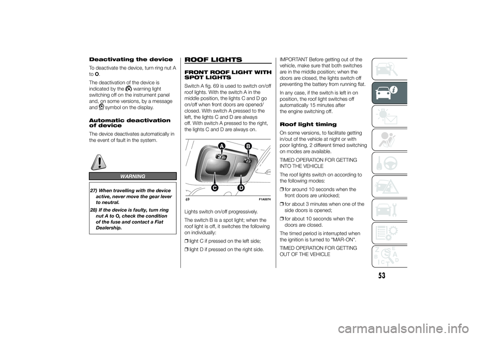
Switch A fig. 69 is used to switch on/off
roof lights. With the switch A in the
middle position, the lights C and D go
on/off when front doors are opened/
closed. With switch A pressed to the
left, the lights C and D are always
off. With switch A pressed to the right,
the lights C and D are always on.
Lights switch on/off progressively.
The switch B is a spot light; when the
roof light is off, it switches the following
on individually:
❒light C if pressed on the left side;
❒light D if pressed on the right side.IMPORTANT Before getting out of the
vehicle, make sure that both switches
are in the middle position; when the
doors are closed, the lights switch off
preventing the battery from running flat.
In any case, if the switch is left in on
position, the roof light switches off
automatically 15 minutes after
the engine switching off.
Roof light timing
On some versions, to facilitate getting
in/out of the vehicle at night or with
poor lighting, 2 different timed switching
on modes are available.
TIMED OPERATION FOR GETTING
INTO THE VEHICLE
The roof lights switch on according to
the following modes:
❒for around 10 seconds when the
front doors are unlocked;
❒for about 3 minutes when one of the
side doors is opened;
❒for about 10 seconds when the
doors are closed.
The timed period is interrupted when
the ignition is turned to "MAR-ON".
TIMED OPERATION FOR GETTING
OUT OF THE VEHICLE69
F1A0074
53
Page 61 of 367
FUEL CUT-OFF
SWITCHThe vehicle is fitted with a safety switch
that, in the event of a crash, comes
into operation by cutting off the fuel
supply and turning off the engine as a
consequence.When the inertia switch cuts in, it cuts
off the fuel supply and also activates
the hazard warning lights, side lights
and courtesy lights while releasing
all the doors and displaying the relevant
message; they are deactivated by
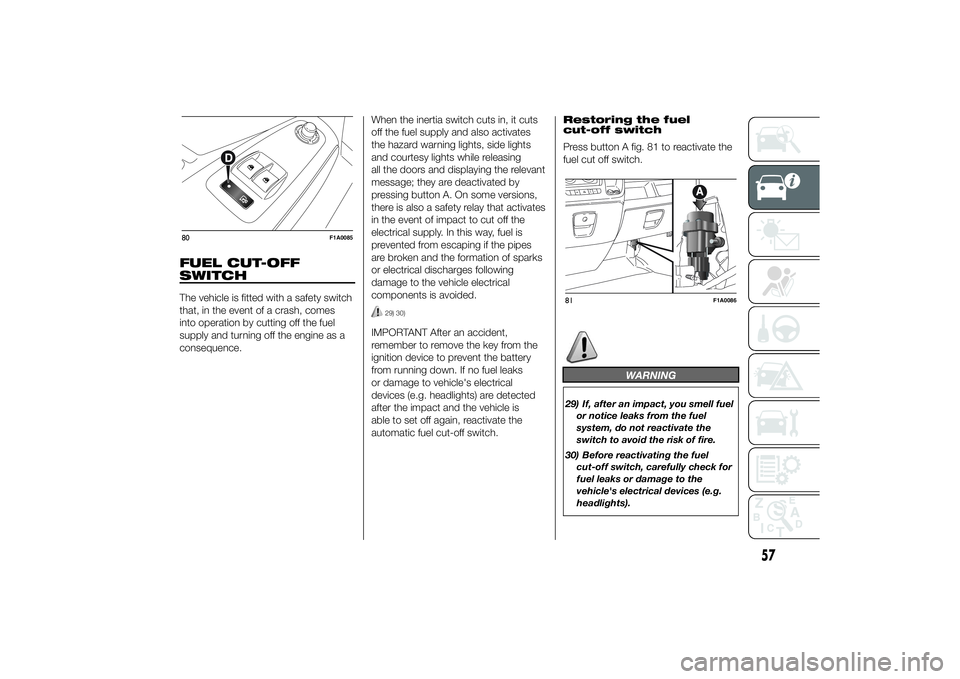
pressing button A. On some versions,
there is also a safety relay that activates
in the event of impact to cut off the
electrical supply. In this way, fuel is
prevented from escaping if the pipes
are broken and the formation of sparks
or electrical discharges following
damage to the vehicle electrical
components is avoided.
29) 30)
IMPORTANT After an accident,
remember to remove the key from the
ignition device to prevent the battery
from running down. If no fuel leaks
or damage to vehicle's electrical
devices (e.g. headlights) are detected
after the impact and the vehicle is
able to set off again, reactivate the
automatic fuel cut-off switch.Restoring the fuel
cut-off switch
Press button A fig. 81 to reactivate the
fuel cut off switch.
WARNING
29) If, after an impact, you smell fuel
or notice leaks from the fuel
system, do not reactivate the
switch to avoid the risk of fire.
30) Before reactivating the fuel
cut-off switch, carefully check for
fuel leaks or damage to the
vehicle's electrical devices (e.g.
headlights).
80
F1A0085
81
F1A0086
57
Page 75 of 367
WARNING
40) Incorrect use of the electric
windows may be dangerous.
Before and during operation,
always check that nobody is
exposed to the risk of being
injured either directly by the
moving window or through
objects getting caught or by being
hit. When leaving the vehicle,
always remove the key from the
ignition switch to avoid the risk of
injury to anyone remaining in
the car due to accidental
operation of the electric windows.
BONNETOPENING
Proceed as follows:
❒open the driver's door to gain access
to the bonnet release handle;
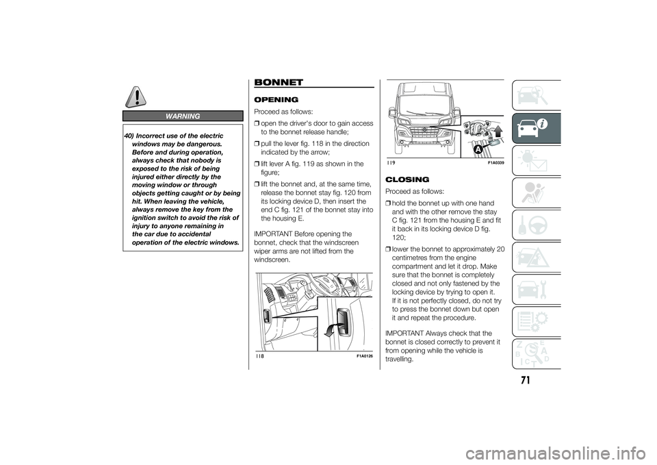
❒pull the lever fig. 118 in the direction
indicated by the arrow;
❒lift lever A fig. 119 as shown in the
figure;
❒lift the bonnet and, at the same time,
release the bonnet stay fig. 120 from
its locking device D, then insert the
end C fig. 121 of the bonnet stay into
the housing E.
IMPORTANT Before opening the
bonnet, check that the windscreen
wiper arms are not lifted from the
windscreen.CLOSING
Proceed as follows:
❒hold the bonnet up with one hand
and with the other remove the stay
C fig. 121 from the housing E and fit
it back in its locking device D fig.
120;
❒lower the bonnet to approximately 20
centimetres from the engine
compartment and let it drop. Make
sure that the bonnet is completely
closed and not only fastened by the
locking device by trying to open it.
If it is not perfectly closed, do not try
to press the bonnet down but open
it and repeat the procedure.
IMPORTANT Always check that the
bonnet is closed correctly to prevent it
from opening while the vehicle is
travelling.118
F1A0126
119
F1A0339
71
Page 96 of 367
14) Always use genuine spare parts
when replacing the bulbs of the
headlights. Other bulbs may
reduce the system performance.
15) Clean the windscreen from
foreign matters such as bird
droppings, insects, snow or ice.
EOBD SYSTEMThe EOBD system (European On Board
Diagnosis) allows continuous diagnosis
of emission-related components on
the vehicle to be made.
It also alerts the driver, by turning on
the
warning light in the instrument
panel (together with relevant message
in the multifunction display, for
versions/markets where provided) when
these components are no longer in
peak condition (see “Warning lights and
messages” paragraph).
The aim of the system is to:
❒monitor system efficiency;
❒indicate an increase in emissions due
to vehicle malfunction;
❒indicate the need to replace
components which have
deteriorated.
The system also has a connector that
can be interfaced with appropriate
equipment, which makes it possible to
read the error codes stored in the
control unit together with a series of
specific parameters for engine
operation and diagnosis. This check
can also be carried out by traffic control
authorities.IMPORTANT After eliminating the
failure, to check the system completely,
Fiat Dealerships run a bench test and,
if necessary, road tests which may
also call for a long journey.
92
KNOW YOUR VEHICLE
Page 112 of 367
SPEEDOMETER (speed
indicator)
Indicator A shows the speed of the car.
REV COUNTER
Indicator C shows the engine revs.
IMPORTANT The electronic injection
control system gradually shuts off
the flow of fuel when the engine
is over-revving, resulting in a gradual
loss of engine power.
When the engine is idling, the rev
counter may indicate a gradual or
sudden increase of the speed.
This is normal and does not indicate a
fault. It may be caused, for example, by
the activation of the climate control
system or fan. In these cases, a slow
change in revs is used to protect the
battery charge.
FUEL LEVEL GAUGE
Needle E shows the amount of fuel left
in the tank.
E - tank empty.
F - tank full (see the description in
paragraph "Vehicle refuelling" in this
chapter).The warning light on the indicator
switches on when there are about
10-12 litres of fuel (for versions with
tank capacity 90-120 l) or 10 l (for
versions with tank capacity 60 l)
remaining in the tank.
Do not travel with the tank nearly empty
to prevent damaging the catalytic
converter.
IMPORTANT The needle will point to E
and the warning light will flash to
indicate a fault in the system. If this is
the case, go to a Fiat Dealership to
have the system checked.
IMPORTANT It is not advisable to
activate the additional Webasto heater
in reserve conditions.
ENGINE COOLANT
TEMPERATURE
INDICATOR
The needle D shows the temperature of
the engine coolant and starts
supplying indications when the fluid
temperature exceeds approx. 50°C. In
normal use, the needle could assume
different positions within the scale,
depending on the usage conditions.
C - Low engine coolant temperature.
H - High engine coolant temperature.The warning light on the indicator may
light up (and a message on the display
may appear on certain versions) to
indicate that the coolant fluid
temperature is too high; in this case,
stop the engine and contact a Fiat
Dealership.
19)
ENGINE OIL LEVEL
GAUGE
(for versions/markets, where provided)
The gauge provides a graphic indication
of the level of oil in the engine.
When the ignition key is turned to
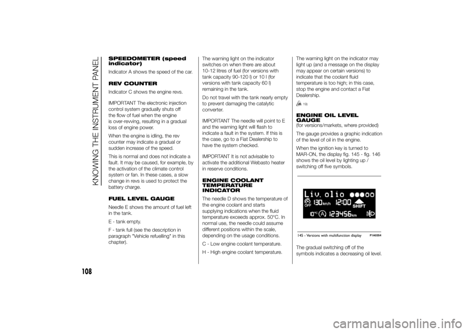
MAR-ON, the display fig. 145 - fig. 146
shows the oil level by lighting up /
switching off five symbols.
The gradual switching off of the
symbols indicates a decreasing oil level.145 - Versions with multifunction display
F1A0354
108
KNOWING THE INSTRUMENT PANEL