wheel FIAT DUCATO BASE CAMPER 2015 Owner handbook (in English)
[x] Cancel search | Manufacturer: FIAT, Model Year: 2015, Model line: DUCATO BASE CAMPER, Model: FIAT DUCATO BASE CAMPER 2015Pages: 367, PDF Size: 19.73 MB
Page 211 of 367
WARNING
153) Give the instruction booklet to
the tyre repair workshop
personnel.
154) Punctures on the sides of the
tyre cannot be repaired. Do not
use the quick tyre repair kit if the
damage is due to running with flat
tyre.
155) If the wheel rim has been
damaged (bent so as to cause air
to leak), the wheel cannot be
repaired. Do not remove the
foreign body (screws or nails)
from the tyre.
156) Do not use the compressor for
more than 20 consecutive
minutes. Risk of overheating.
Tyres repaired with the quick tyre
repair kit must only be used
temporarily, as the kit is not
suitable for a definitive repair.157) The bottle contains ethylene
glycol. It contains latex that might
cause allergic reactions. It is
harmful if swallowed. It is irritant
for the eyes. It may cause
sensitisation if inhaled or on
contact. Avoid contact with eyes,
skin and clothes. In the event of
contact, wash immediately with
plenty of water. Do not induce
vomiting if swallowed. Rinse your
mouth and drink plenty of water.
Call a doctor immediately. Keep
out of the reach of children. The
product must not be used by
asthmatics. Do not breathe in the
vapours during insertion and
suction. Call a doctor immediately
if allergic reactions are noted.
Store the bottle in its proper
compartment, away from sources
of heat. The sealant has an expiry
date. Replace the bottle if the
sealant has expired.
158) Wear the protective gloves
provided together with the quick
tyre repair kit.
159) affix the adhesive label in an
easy-to-see position for the driver
as a reminder that the tyre has
been treated with the quick tyre
repair kit. Drive carefully,
particularly on bends. Do not
exceed 80 km/h. Do not
accelerate or brake suddenly.160) If the pressure falls below 3
bars, do not drive any further: the
Fix & Go automatic quick tyre
repair kit cannot guarantee proper
hold because the tyre is too much
damaged. Contact a Fiat
Dealership.
161) You must inform the dealership
that the tyre has been repaired
using the quick tyre repair kit.
Give the booklet to the personnel
who will be handling the tyre
treated with the repair kit.
162) If different tyres from the ones
supplied with the vehicle are
used, it may not be possible to
carry out the repair. If the tyres
are replaced, it is advisable to use
those approved by the
manufacturer. Consult a Fiat
Dealership.
IMPORTANT
44) Punctures caused by foreign
bodies can be repaired if the
damage does not exceed 4 mm on
the tread and on the shoulder of
the tyre.
207
Page 217 of 367
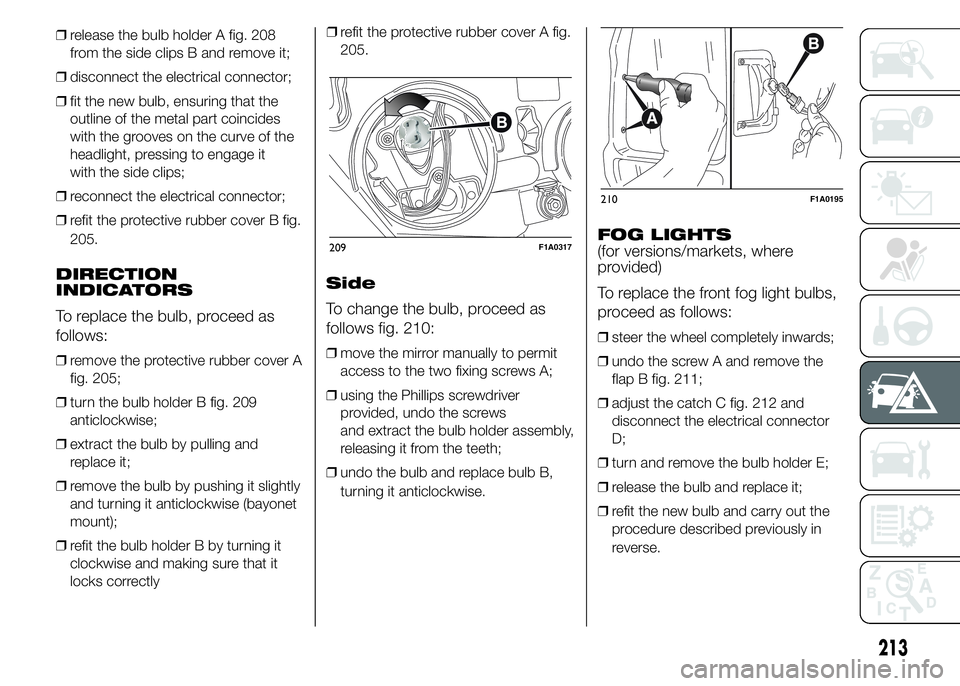
❒release the bulb holder A fig. 208
from the side clips B and remove it;
❒disconnect the electrical connector;
❒fit the new bulb, ensuring that the
outline of the metal part coincides
with the grooves on the curve of the
headlight, pressing to engage it
with the side clips;
❒reconnect the electrical connector;
❒refit the protective rubber cover B fig.
205.
DIRECTION
INDICATORS
To replace the bulb, proceed as
follows:
❒remove the protective rubber cover A
fig. 205;
❒turn the bulb holder B fig. 209
anticlockwise;
❒extract the bulb by pulling and
replace it;
❒remove the bulb by pushing it slightly
and turning it anticlockwise (bayonet
mount);
❒refit the bulb holder B by turning it
clockwise and making sure that it
locks correctly❒refit the protective rubber cover A fig.
205.
Side
To change the bulb, proceed as
follows fig. 210:
❒move the mirror manually to permit
access to the two fixing screws A;
❒using the Phillips screwdriver
provided, undo the screws
and extract the bulb holder assembly,
releasing it from the teeth;
❒undo the bulb and replace bulb B,
turning it anticlockwise.
FOG LIGHTS
(for versions/markets, where
provided)
To replace the front fog light bulbs,
proceed as follows:
❒steer the wheel completely inwards;
❒undo the screw A and remove the
flap B fig. 211;
❒adjust the catch C fig. 212 and
disconnect the electrical connector
D;
❒turn and remove the bulb holder E;
❒release the bulb and replace it;
❒refit the new bulb and carry out the
procedure described previously in
reverse.
209F1A0317
210F1A0195
213
Page 225 of 367
Dashboard fuse box
fig. 226 - fig. 227
DEVICE PROTECTED FUSE AMPERE
Right dipped beam headlight F12 7,5
Left dipped headlight F13 7,5
Engine compartment control unit relay, dashboard control unit relay (+key) F31 5
Lighting of roof lights in the passenger compartment (+battery) F32 7,5
Battery monitoring sensor for Start&Stop versions (+battery) F33 7,5
Minibus interior lights (emergency) F34 7,5
Radio, climate control, alarm, tachograph, battery disconnecting control unit,
Webasto timer (+battery)F36 10
Brake light control (main), third brake light, instrument panel (+key) F37 7,5
Door lock (+battery) F38 20
Windscreen wiper (+key) F43 20
Driver's side electric window F47 20
Passenger side electric window F48 20
Parking sensor control unit, radio, steering wheel controls, central control panel,
left control panel, auxiliary panel, battery disconnecting control unit (+key)F49 5
Climate control, power steering control unit, reverse lights, diesel filter water
sensor, flow meter, tachograph (+key)F51 5
Instrument panel (+battery) F53 7,5
AbsentF89 -
221
Page 231 of 367
The front ring is located in the tool
box beneath the passenger side
seat. On versions with Fix&Go
kit and without spare wheel, the
tool box is available only on request
for versions/markets where
provided.In the absence of the tool box the
vehicle front tow hook is housed
in the on-board documentation
container, together with the Owner
Handbook.
To use it, proceed as follows:
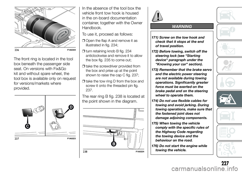
❒Open the flap A and remove it as
illustrated in fig. 234;
❒turn retaining knob B fig. 234
anticlockwise and remove it to allow
the box fig. 235 to come out;
❒take the screwdriver provided from
the box and prise up at the point
shown to raise the cap C fig. 237;
❒take the tow ring D from the box and
screw it onto the threaded pin fig.
237.
The rear ring B fig. 238 is located at
the point shown in the diagram.
WARNING
171) Screw on the tow hook and
check that it stops at the end
of travel position.
172) Before towing, switch off the
steering lock (see "Starting
device" paragraph under the
"Knowing your car" section).
173) Remember that the brake servo
and the electric power steering
are not available during towing
operations. Significantly greater
force must be exerted on the
brake pedal and on the steering
wheel to operate them.
174) Do not use flexible cables for
towing and avoid jerking. During
towing operations, make sure that
the fastened joint does not
damage adjoining components.
175) When towing the vehicle
comply with the specific rules of
the Highway Code regarding
the towing device and the
behaviour on the road.
176) Do not start the engine while
towing the vehicle.
236F1A0344
237F1A0223
238F1A0224
227
Page 233 of 367
SERVICING AND MAINTENANCE
Correct maintenance permits the
performance of the car to be
maintained over time, as well as
limited running costs and
safeguarding the efficiency of the
safety systems.
This chapter explains how.SCHEDULED SERVICING ...............230
SCHEDULED SERVICING PLAN .....231
PERIODIC CHECKS ........................234
DEMANDING VEHICLE USE ...........234
CHECKING LEVELS........................235
AIR CLEANER/POLLEN FILTER ......241
BATTERY ........................................242
WHEELS AND TYRES.....................245
RUBBER HOSES ............................246
WINDSCREEN WIPER ....................246
BODYWORK ...................................248
INTERIORS .....................................250
229
Page 243 of 367
POWER STEERING
FLUID
188)
3)
51)
Check that the liquid contained in
the tank is at the maximum level.
This operation must be carried out
with the vehicle level and with
the engine off and cold.
Proceed as follows:
❒remove the plastic cover A fig. 242,
rotating the locking screws B fig.
242 counter-clockwise, to access the
filler of the reservoir;
❒check that the fluid level is up to the
MAX mark on the dipstick attached
to the fuel cap F fig. 239 - fig. 240
- fig. 241 (use the level shown on the
20°C side of the dipstick to check
when cold).
If the level of the fluid in the tank is
lower than the specified level,
top up using only one of the
products indicated in the "Fluid and
lubricants" table in the "Technical
specifications" section, proceeding
as follows:
❒Start the engine and wait for the fluid
level in the tank to stabilise.❒With the engine running, turn the
steering wheel from right to left
fully several times.
❒Top up the fuel to the MAX level and
then retighten the cap.
WINDSCREEN/REAR
WINDOW WASHER
FLUID
183) 184)
To add fluid:
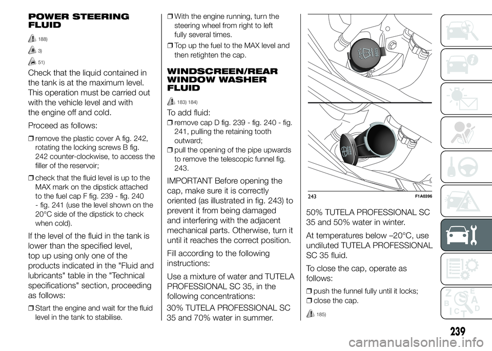
❒remove cap D fig. 239 - fig. 240 - fig.
241, pulling the retaining tooth
outward;
❒pull the opening of the pipe upwards
to remove the telescopic funnel fig.
243.
IMPORTANT Before opening the
cap, make sure it is correctly
oriented (as illustrated in fig. 243) to
prevent it from being damaged
and interfering with the adjacent
mechanical parts. Otherwise, turn it
until it reaches the correct position.
Fill according to the following
instructions:
Use a mixture of water and TUTELA
PROFESSIONAL SC 35, in the
following concentrations:
30% TUTELA PROFESSIONAL SC
35 and 70% water in summer.50% TUTELA PROFESSIONAL SC
35 and 50% water in winter.
At temperatures below –20°C, use
undiluted TUTELA PROFESSIONAL
SC 35 fluid.
To close the cap, operate as
follows:
❒push the funnel fully until it locks;
243F1A0396
239
❒close the cap.
185)
Page 249 of 367
WHEELS AND TYRES
Check the pressure of each tyre,
including the space-saver wheel,
approximately every two weeks and
before long journeys: the pressure
should be checked with the tyre
rested and cold.
It is normal for the pressure to
increase when the vehicle is used;
for the correct tyre inflation
pressure, see “Wheels” in the
“Technical specifications” section.
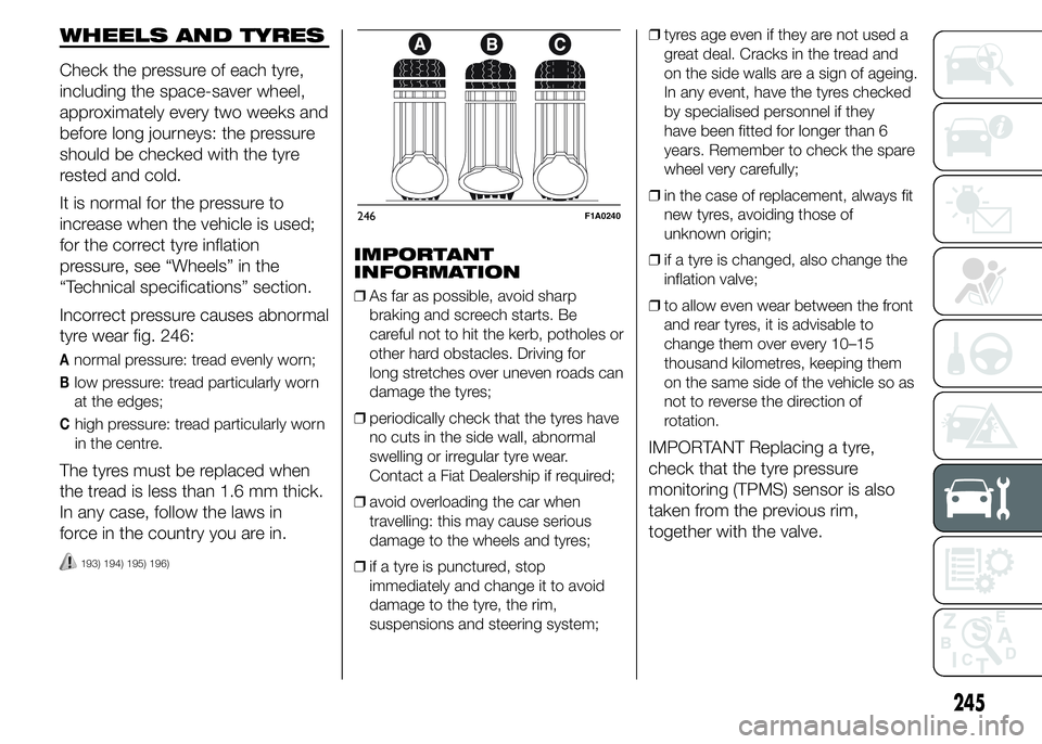
Incorrect pressure causes abnormal
tyre wear fig. 246:
Anormal pressure: tread evenly worn;
Blow pressure: tread particularly worn
at the edges;
Chigh pressure: tread particularly worn
in the centre.
The tyres must be replaced when
the tread is less than 1.6 mm thick.
In any case, follow the laws in
force in the country you are in.
193) 194) 195) 196)
IMPORTANT
INFORMATION
❒As far as possible, avoid sharp
braking and screech starts. Be
careful not to hit the kerb, potholes or
other hard obstacles. Driving for
long stretches over uneven roads can
damage the tyres;
❒periodically check that the tyres have
no cuts in the side wall, abnormal
swelling or irregular tyre wear.
Contact a Fiat Dealership if required;
❒avoid overloading the car when
travelling: this may cause serious
damage to the wheels and tyres;
❒if a tyre is punctured, stop
immediately and change it to avoid
damage to the tyre, the rim,
suspensions and steering system;❒tyres age even if they are not used a
great deal. Cracks in the tread and
on the side walls are a sign of ageing.
In any event, have the tyres checked
by specialised personnel if they
have been fitted for longer than 6
years. Remember to check the spare
wheel very carefully;
❒in the case of replacement, always fit
new tyres, avoiding those of
unknown origin;
❒if a tyre is changed, also change the
inflation valve;
❒to allow even wear between the front
and rear tyres, it is advisable to
change them over every 10–15
thousand kilometres, keeping them
on the same side of the vehicle so as
not to reverse the direction of
rotation.
IMPORTANT Replacing a tyre,
check that the tyre pressure
monitoring (TPMS) sensor is also
taken from the previous rim,
together with the valve.
246F1A0240
245
Page 250 of 367
WARNING
193) Remember that the road
holding qualities of your vehicle
also depend on the correct
inflation pressure of the tyres.
194) If the pressure is too low, the
tyre will overheat and could be
seriously damaged.
195) Avoid switching the tyres from
the right side of the vehicle to the
left side and vice versa.
196) Never submit alloy rims to
repainting treatments requiring
the use of temperatures
exceeding 150°C. The mechanical
properties of the wheels could
be impaired.
RUBBER HOSES
As far as the brake system and fuel
supply system rubber hoses are
concerned, follow the "Scheduled
Servicing Plan" in this chapter
carefully.
Ozone, high temperatures and
prolonged lack of fluid in the
system may cause hardening and
cracking of the hoses, with possible
leaks. Careful checking is therefore
necessary.
WINDSCREEN
WIPER
BLADES
Periodically clean the rubber part
using special products; TUTELA
PROFESSIONAL SC 35 is
recommended.
Replace the blades if the rubber
edge is deformed or worn. In any
case, it is advisable to replace them
approximately once a year.
A few simple precautions can
reduce the possibility of damage to
the blades:
❒if the temperature falls below zero,
make sure that ice has not frozen
the rubber against the glass. Use a
de-icing product to release it if
required;
❒remove any snow from the glass: in
addition to protecting the blades,
this prevents effort on the motor and
overheating;
❒do not operate the windscreen and
rear window wipers on dry glass.
197)
246
SERVICING AND MAINTENANCE
Page 252 of 367
BODYWORK
PROTECTION AGAINST
ATMOSPHERIC
AGENTS
The main causes of corrosion are
the following:
❒atmospheric pollution;
❒salty air and humidity (coastal areas,
or hot humid climates);
❒seasonal environmental conditions.
The abrasive action of wind-borne
atmospheric dust and sand, as well
as mud and gravel raised by other
vehicles is also not to be
underestimated.
On your vehicle, Fiat has
implemented the best
manufacturing technologies to
effectively protect the bodywork
against corrosion.
These include:
❒painting products and systems which
give the vehicle particular resistance
to corrosion and abrasion;
❒Use of galvanised (or pretreated)
steel sheets, with high resistance
to corrosion;❒spraying the underbody, engine
compartment, wheelhouse internal
parts and other parts with highly
protective wax products;
❒spraying of plastic parts, with a
protective function in the more
exposed points: underdoor, inner
wing, edges, etc;
❒use of “open” boxed sections to
prevent condensation and pockets of
moisture from triggering rust inside.
VEHICLE BODY AND
UNDERBODY
WARRANTY
Your vehicle is covered by warranty
against perforation due to corrosion
of any original element of the
structure or body.
For the general terms of this
warranty, refer to the Warranty
Booklet.
ADVICE FOR
PRESERVING THE
BODYWORK
Paintwork
Paintwork does not only serve an
aesthetic purpose, but also
protects the underlying sheet metal.Touch up abrasions and scratches
immediately to prevent rust
formation. Only use genuine spare
paint products for touch-ups (see
“Bodywork paint identification
plate” in the “Technical
Specifications” section).
Normal maintenance of paintwork
consists in washing the car: the
frequency depends on the
conditions and environment where
the car is used.
For example, it is advisable to wash
the vehicle more often in areas
with high levels of environmental
pollution or on roads spread with
salt.
To correctly wash the vehicle,
proceed as follows:
❒wash the bodywork using a low
pressure jet of water;
❒wipe a sponge with a slightly soapy
solution over the bodywork,
frequently rinsing the sponge;
248
SERVICING AND MAINTENANCE
❒rinse well with water and dry with a
jet of air or a chamois leather.
Page 254 of 367
IMPORTANT
55) Some car washes with old-style
blades and/or in a poor state of
repair can damage the paintwork,
facilitating the formation of lines
that give the paint a dull/misty
appearance, especially on dark
colours. If this happens, lightly
polish the paintwork with
appropriate products.
IMPORTANT
5) Detergents cause water pollution.
The vehicle should be washed in
areas equipped for collecting
and purifying the liquid used in
the washing process.
INTERIORS
Regularly check that water is not
trapped under the mats (due to
water dripping off shoes, umbrellas,
etc.), as this could cause oxidation
of the sheet metal.
198) 199)
SEATS AND FABRIC
PARTS
Remove dust with a soft brush or a
vacuum cleaner. It is advisable to
use a moist brush on velvet
upholstery.
Rub the seats with a sponge
moistened with a solution of water
and mild soap.
PLASTIC PARTS
It is advisable to clean interior parts
with a moist cloth and a solution
of water and non-abrasive mild
soap. Use specific products for
cleaning plastic, without solvents
and specifically designed to prevent
damage to the appearance and
colour of the treated parts, to
remove grease and tough stains.IMPORTANT Do not use alcohol,
petrols or derivatives to clean
the instrument panel glass.
LEATHER STEERING
WHEEL/GEAR
KNOB/HANDBRAKE
(for versions/markets, where
provided)
These components must be
cleaned with mild soap and water
only. Never use alcohol or
alcohol-based products.
Read the product label carefully
before using specific products for
cleaning the interiors: make sure
that the product does not contain
spirits or alcohol-based
substances.
If, when cleaning the windscreen
with special products, window
cleaner accidentally drips onto the
leather of the steering wheel/gear
lever knob/handbrake, wipe away
immediately and then wash the
affected area with mild soap and
water.
250
SERVICING AND MAINTENANCE