dashboard FIAT DUCATO BASE CAMPER 2016 Owner handbook (in English)
[x] Cancel search | Manufacturer: FIAT, Model Year: 2016, Model line: DUCATO BASE CAMPER, Model: FIAT DUCATO BASE CAMPER 2016Pages: 387, PDF Size: 20.76 MB
Page 71 of 387
POWER SOCKET
(for versions/markets, where provided)
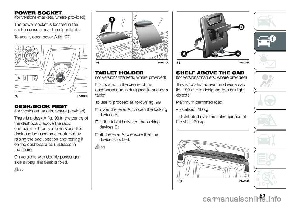
The power socket is located in the
centre console near the cigar lighter.
To use it, open cover A fig. 97.
DESK/BOOK REST
(for versions/markets, where provided)
There is a desk A fig. 98 in the centre of
the dashboard above the radio
compartment; on some versions this
desk can be used as a book rest by
raising the back section and resting it
on the dashboard as illustrated in
the figure.
On versions with double passenger
side airbag, the desk is fixed.
32)
TABLET HOLDER
(for versions/markets, where provided)
It is located in the centre of the
dashboard and is designed to anchor a
tablet.
To use it, proceed as follows fig. 99:
❒lower the lever A to open the locking
devices B;
❒fit the tablet between the locking
devices B;
❒lift the lever A to ensure that the
device is locked.
33)
SHELF ABOVE THE CAB
(for versions/markets, where provided)
This is located above the driver's cab
fig. 100 and is designed to store light
objects.
Maximum permitted load:
– localised: 10 kg
– distributed over the entire surface of
the shelf: 20 kg
97F1A0308
98F1A010299F1A0342
100F1A0103
67
Page 76 of 387
When the doors are unlocked, the LED
is off and pressing the button again
centrally locks all the doors. The doors
will be locked only if all the doors are
properly shut.
Following the locking of the doors
using:
❒remote control
❒door pawl
they cannot be unlocked using the
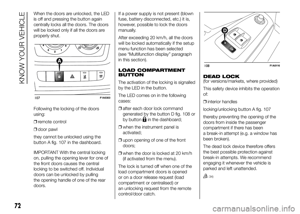
button A fig. 107 in the dashboard.
IMPORTANT With the central locking
on, pulling the opening lever for one of
the front doors causes the central
locking to be switched off. Individual
doors can be unlocked by pulling
the opening handle of one of the rear
doors.If a power supply is not present (blown
fuse, battery disconnected, etc.) it is,
however, possible to lock the doors
manually.
After exceeding 20 km/h, all the doors
will be locked automatically if the setup
menu function has been selected
(see “Multifunction display” paragraph
in this section).
LOAD COMPARTMENT
BUTTON
The activation of the locking is signalled
by the LED in the button.
The LED comes on in the following
cases:
❒after each door lock command
generated by the button D fig. 108 or
by button
in the dashboard;
❒when the instrument panel is
activated;
❒upon opening of one of the front
doors;
❒when the door is locked at 20 km/h
(if activated from the menu).
The lock is turned off when one of the
load compartment doors is opened
or on a door release request (load
compartment or centralised) or
an unlocking request from the remote
control/door catch.DEAD LOCK
(for versions/markets, where provided)
This safety device inhibits the operation
of:
❒interior handles
locking/unlocking button A fig. 107
thereby preventing the opening of the
doors from inside the passenger
compartment if there has been
a break-in attempt (e.g. a window has
been broken).
The dead lock device therefore offers
the best possible protection against
break-in attempts. We recommend
engaging it whenever the vehicle is
parked and left unattended.
34)
107F1A0303
108F1A0116
72
KNOW YOUR VEHICLE
Page 77 of 387
Device activation
The dead lock device is automatically
activated on every door with two short
presses on the button
on the key
with remote control fig. 104.
Device activation is indicated by 3
flashes of the direction indicators and a
flash of the LED on button A fig. 107
on the dashboard.
If one or more of the doors is not
perfectly shut, the dead lock device will
not be activated, thus preventing a
person getting into the car through the
open door and, on shutting, it,
remaining stuck inside the passenger
compartment.
Device deactivation
The system is disabled automatically on
every door in the following cases:
❒if the mechanical key is turned to the
opening position in the driver's door;
❒by unlocking the doors using the
remote control;
❒by turning the ignition key to the
MAR-ON position.SLIDING SIDE DOOR
35) 36)
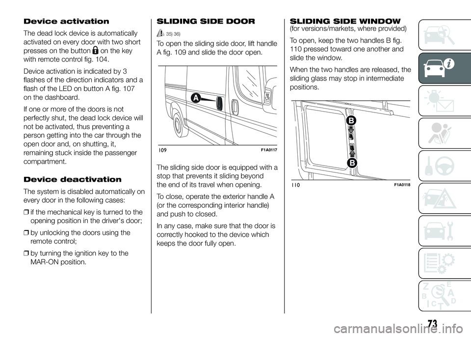
To open the sliding side door, lift handle
A fig. 109 and slide the door open.
The sliding side door is equipped with a
stop that prevents it sliding beyond
the end of its travel when opening.
To close, operate the exterior handle A
(or the corresponding interior handle)
and push to closed.
In any case, make sure that the door is
correctly hooked to the device which
keeps the door fully open.SLIDING SIDE WINDOW
(for versions/markets, where provided)
To open, keep the two handles B fig.
110 pressed toward one another and
slide the window.
When the two handles are released, the
sliding glass may stop in intermediate
positions.
109F1A0117
110F1A0118
73
Page 90 of 387
65) The HBA system is an aid for the
driver, who must always pay full
attention while driving. The
responsibility always rests with
the driver. The features of the
HBA system must never be tested
in imprudent or dangerous ways,
with the possibility of putting
the safety of the driver, occupants
or other road users at risk.
66) The performance of a vehicle
with ERM must never be tested
in imprudent or dangerous ways,
with the possibility of putting
the safety of the driver or other
people at risk.
IMPORTANT
8) Prolonged use of the system may
overheat the braking system. If
the brakes overheat, the HDC
system, when active, will be
gradually deactivated after
suitably informing the driver (the
LED on the button turns off): it
can be reactivated only when the
brakes have cooled sufficiently.
The distance that can be covered
depends on the temperature of
the brakes and therefore on the
gradient, load and speed of the
vehicle.
TRACTION PLUS
SYSTEM
(for versions/markets, where provided)
Traction Plus is a driving aid, useful
for setting off in poor grip conditions on
non-homogeneous road surfaces
(snow/asphalt, ice/asphalt, mud/
asphalt, etc.), which allows the drive
force to be distributed adequately
on the engine axle when one of the two
drive wheels slips.
Traction Plus acts by braking the wheel
with poor grip (or slipping more than
the others), thereby transferring the
drive force to that which has greater
grip on the ground.
This function can be activated manually
by pressing button A on the dashboard
fig. 127 and operates under 50 km/h.
When this speed is exceeded, it is
automatically deactivated (the LED on
the button is still on) and it is
reactivated again when the speed falls
below 30 km/h.
67) 68)
86
KNOW YOUR VEHICLE
Page 95 of 387
OPERATION
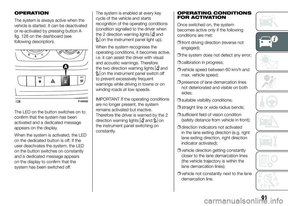
The system is always active when the
vehicle is started. It can be deactivated
or re-activated by pressing button A
fig. 128 on the dashboard (see
following description).
The LED on the button switches on to
confirm that the system has been
activated and a dedicated message
appears on the display.
When the system is activated, the LED
on the dedicated button is off. If the
user deactivates the system, the LED
on the button switches on constantly
and a dedicated message appears
on the display to confirm that the
system has been switched off.The system is enabled at every key
cycle of the vehicle and starts
recognition of the operating conditions
(condition signalled to the driver when
the 2 direction warning lights
and
on the instrument panel light up).
When the system recognises the
operating conditions, it becomes active,
i.e. it can assist the driver with visual
and acoustic warnings. Therefore
the two direction warning lights
and
on the instrument panel switch off
to prevent excessively frequent
warnings while driving in towns or on
winding roads at low speeds.
IMPORTANT If the operating conditions
are no longer present, the system
remains activated but inactive.
Therefore the driver is warned by the 2
direction warning lights
andon
the instrument panel switching on
constantly.OPERATING CONDITIONS
FOR ACTIVATION
Once switched on, the system
becomes active only if the following
conditions are met:
❒front driving direction (reverse not
engaged);
❒the system does not detect any error;
❒calibration in progress;
❒vehicle speed between 60 km/h and
max. vehicle speed;
❒presence of lane demarcation lines
not deteriorated and visible on both
sides;
❒suitable visibility conditions;
❒straight line or wide radius bends;
❒sufficient field of vision condition
(safety distance from vehicle in front);
❒direction indicators not activated
in the lane exiting direction (e.g. right
lane exiting direction, right direction
indicator activated);
❒vehicle direction getting constantly
closer to the lane demarcation lines
(the vehicle trajectory is within the
lane demarcation lines);
❒vehicle not constantly next to the lane
demarcation line.
128F1A0322
91
Page 96 of 387
SYSTEM ACTIVATION/
DEACTIVATION
When the system is active, if the vehicle
gets close to one of the limit lines or
one of the two lane demarcation lines,
the driver is warned with an acoustic
signal (coming from the crossed line
side if the vehicle is equipped with the
radio navigation system) along with
the corresponding direction warning
light (
or) lighting up.
If the driver turns on the direction
indicator in order to change lanes or for
overtaking, then the system will switch
off the driver warning.
If the driver keeps deliberately with the
lane change manoeuvre, the system
interrupts the warning, remaining
enabled if the operating conditions are
not satisfied or active if the operating
conditions are exceeded (see the
dedicated paragraph).SWITCHING OFF THE
SYSTEM
Manual mode
The system can be switched off by
pressing button A fig. 128 on the
dashboard.
The LED on the button switches on and
a message appears on the display to
confirm that the system has been
switched off.
Automatic mode
If the Start&Stop is active the system
deactivates automatically. The system
will reactivate and check its operating
conditions again after the vehicle has
been started.
SYSTEM FAILURE
In the case of malfunction the system
signals the fault to the driver with a
message on the display, an acoustic
warning and switching on of the icon
on the display (for versions/markets,
where provided).IMPORTANT INFORMATION
The Driving Advisor cannot operate due
to a not perfectly balanced and
excessive load.
The operation of the system can be
adversely affected in some cases
by the morphology of the territory/road
being driven on (e.g. driving over
humps), poor visibility conditions (e.g.
fog, rain, snow), extreme light
conditions (e.g. glare of the sun,
darkness), lack of cleanliness
or damage, even partial, to the
windscreen in the area in front of the
camera.
The Driving Advisor cannot operate
following a malfunction of the following
safety systems: ABS, ESP, ASR and
Traction Plus.
The operation of the system can be
adversely affected by poor visibility
conditions (e.g. fog, rain, snow),
extreme light conditions (glare of the
sun, darkness), lack of cleaning or
damage, even partial, to the
windscreen in the area in front the
camera.
The area of the windscreen by the
camera must not be partly or totally
obscured by objects (e.g. stickers,
protective film, etc.).
92
KNOW YOUR VEHICLE
Page 106 of 387
WARNING
86) The responsibility for parking
and other dangerous manoeuvres
always and in every case lies
with the driver. While carrying out
these manoeuvres, always make
sure that no people (especially
children) or animals are in the
area concerned. The parking
sensors are used to assist the
driver, who must never allow his
attention to lapse during
potentially dangerous
manoeuvres, even those executed
at low speeds.
START&STOP
SYSTEM
IN BRIEF
The Start&Stop device automatically
stopsthe engine each time the
vehicle is stationary and starts it
again when the driver wants to move
off. This improves the efficiency of
the vehicle by reducing fuel
consumption, the emission of harmful
gases and noise pollution.
OPERATING MODES
Engine stopping mode
WITH MANUAL GEARBOX
With the vehicle stationary, the engine
stops with the gearbox in neutral and
the clutch pedal released.
NoteThe engine can only be stopped
automatically after exceeding a speed
of about 10 km/h, to prevent the engine
from being repeatedly stopped when
driving at walking pace.
Engine stopping is signalled by the
icon on the display.Engine restarting mode
WITH MANUAL GEARBOX
Depress the clutch pedal to restart the
engine.
MANUAL ACTIVATION
AND DEACTIVATION OF
THE SYSTEM
To activate/deactivate the system
manually, press the
fig. 133 button
on the dashboard control trim.
Start&Stop system
activation
A message will appear on the display
when the Start&Stop system is
activated. In this condition, the LED on
the
button is off.
Start&Stop system
deactivation
A message will appear on the display
when the Start&Stop system is
deactivated.
The LED on the
button is on when
the system is deactivated.
102
KNOW YOUR VEHICLE
Page 146 of 387
Warning lights on
panelWhat it means What to do
amberUREA INJECTION SYSTEM FAILURE
The warning light switches on, together with a
dedicated message on the display (for versions/
markets, where provided) if a fluid not conforming
with the nominal characteristics is inserted o if an
average consumption of UREA over 50% is
detected.Contact a Fiat Dealership as soon as possible.
If the fault is not resolved, a further warning will be
given at the following remaining km before the
vehicle restart will be prevented:
❒400 km
❒320 km
❒240 km
When 200 km will remain to prevent the engine
restart, a continuous dedicated message will
appear on the dashboard (for versions/markets
where provided) accompanied by a buzzer sound
amberABS FAILURE
When the key is turned to MAR-ON, the warning
light switches on but should switch off after a few
seconds.
The warning light switches on to indicate a
system fault. In this case the braking system
maintains its efficiency unaltered but without the
advantage of the ABS system. The display shows
the dedicated message.Drive carefully and contact a Fiat Dealership as
soon as possible.
142
KNOWING THE INSTRUMENT PANEL
Page 155 of 387
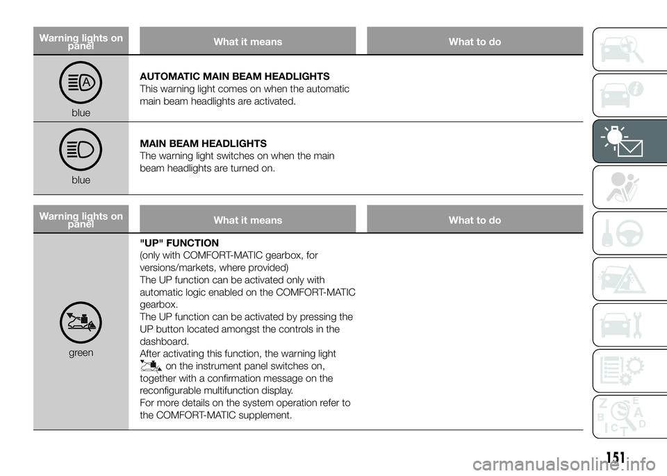
Warning lights on
panelWhat it means What to do
blueAUTOMATIC MAIN BEAM HEADLIGHTS
This warning light comes on when the automatic
main beam headlights are activated.
blueMAIN BEAM HEADLIGHTS
The warning light switches on when the main
beam headlights are turned on.
Warning lights on
panelWhat it means What to do
green"UP" FUNCTION
(only with COMFORT-MATIC gearbox, for
versions/markets, where provided)
The UP function can be activated only with
automatic logic enabled on the COMFORT-MATIC
gearbox.
The UP function can be activated by pressing the
UP button located amongst the controls in the
dashboard.
After activating this function, the warning light
on the instrument panel switches on,
together with a confirmation message on the
reconfigurable multifunction display.
For more details on the system operation refer to
the COMFORT-MATIC supplement.
151
Page 172 of 387

instrument panel to make sure
that they are actually deactivated.
The passenger seat must also be
positioned back as far as possible
in order to avoid the child
restraint system from coming into
contact with the dashboard.
114) The figures are indicative and
for assembly purposes only. Fit
the child restraint system
according to the instructions,
which must be included.
115) Some child restraint systems
for weight group 0 and 1 have a
rear attachment to the car seat
belts and its own seat belts for
securing the child. Due to their
weight, they may be dangerous if
incorrectly mounted (e.g. if
fastened to the vehicle seat belts
placing a cushion in between).
Follow the assembly instructions
carefully.SETUP FOR
“UNIVERSAL
ISOFIX” CHILD
RESTRAINT SYSTEM
Provision has been made on the vehicle
to fit Universal Isofix child restraint
systems, a new European standardised
system for carrying children safely.
An example of a child restraint system
is shown in fig. 163.Due to its different attachment system,
the child restraint system must be
secured using the special lower metal
rings A fig. 164, positioned between
rear backrest and cushion. The upper
belt (provided with the child restraint
system) must be then secured to ring B
fig. 165 located in the lower part of
the seat. It is possible to have a mixed
assembly of traditional child restraint
systems and Universal Isofix ones.
163F1A0155164F1A0156
168
SAFETY