parking sensors FIAT DUCATO BASE CAMPER 2016 Owner handbook (in English)
[x] Cancel search | Manufacturer: FIAT, Model Year: 2016, Model line: DUCATO BASE CAMPER, Model: FIAT DUCATO BASE CAMPER 2016Pages: 387, PDF Size: 20.76 MB
Page 10 of 387
.
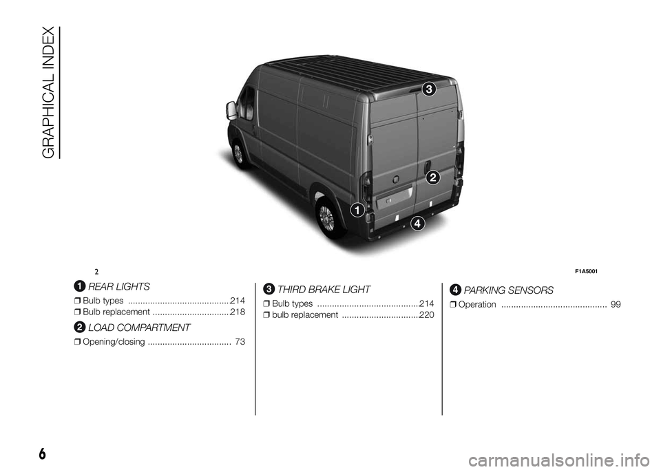
REAR LIGHTS
❒Bulb types ..........................................214
❒Bulb replacement ................................218
LOAD COMPARTMENT
❒Opening/closing .................................. 73
THIRD BRAKE LIGHT
❒Bulb types ..........................................214
❒bulb replacement ................................220
PARKING SENSORS
❒Operation ........................................... 99
2F1A5001
6
GRAPHICAL INDEX
Page 13 of 387
KNOW YOUR VEHICLE
In-depth knowledge of your new vehicle
starts here.
The booklet that you are reading simply
and directly explains how it is made
and how it works.
That’s why we advise you to read it
seated comfortably on board, so that
you can see what is described here for
yourself.SYMBOLS ...................................... 11
THE FIAT CODE SYSTEM ............... 11
THE KEYS....................................... 12
ELECTRONIC ALARM..................... 14
IGNITION SWITCH .......................... 15
SEATS ............................................ 16
HEAD RESTRAINTS ........................ 24
STEERING WHEEL ......................... 25
REAR VIEW MIRRORS .................... 25
HEATING AND VENTILATION.......... 28
DIFFUSERS..................................... 29
HEATING AND VENTILATION
CONTROLS .................................... 29
MANUAL CLIMATE CONTROL
SYSTEM ......................................... 32
AUTOMATIC CLIMATE CONTROL
SYSTEM ......................................... 35
ADDITIONAL HEATER ..................... 41
INDEPENDENT ADDITIONAL
HEATER .......................................... 41
EXTERNAL LIGHTS......................... 47
WINDOW CLEANING ...................... 51
CRUISE CONTROL ......................... 54
ROOF LIGHTS ................................ 57
CONTROLS .................................... 59
FUEL CUT-OFF SWITCH ................ 62INTERIOR FITTINGS ...................... 63
TACHOGRAPH ............................... 68
SPEED BLOCK ............................... 69
SELF-LEVELLING AIR
SUSPENSION ................................. 69
DOORS ........................................... 70
ELECTRIC WINDOWS .................... 76
BONNET ......................................... 77
ROOF RACK/SKI RACK .................. 79
HEADLIGHTS.................................. 79
ABS ................................................ 80
ESC (ELECTRONIC STABILITY
CONTROL) SYSTEM ....................... 82
TRACTION PLUS SYSTEM ............. 86
TPMS (TYRE PRESSURE
MONITORING SYSTEM) ................. 87
DRIVING ADVISOR ......................... 90
REAR CAMERA (PARKVIEW®
REAR BACK UP CAMERA) ............. 95
TRAFFIC SIGN RECOGNITION ....... 97
EOBD SYSTEM............................... 98
PARKING SENSORS....................... 99
START&STOP SYSTEM ..................101
ADDITIVE FOR DIESEL EMISSIONS
ADBLUE (UREA)..............................104
9
Page 80 of 387
WARNING
34) Once the dead lock system is
engaged it is impossible to open
the doors from inside the vehicle.
Therefore, before engaging the
system check that there is no one
left inside. If the remote control
battery is flat, the system can be
disengaged only by inserting
the key metal insert in either of
the door locks as described
previously: in this case the device
remains active only for the rear
doors.
35) Before leaving the vehicle
parked with sliding doors open,
always check that the latch is
engaged.
36) Do not move the vehicle with
side doors open.37) Before setting off after parking
or before moving the vehicle in
any way, ensure that the
footboard is fully stowed away. As
the movement of the platform is
linked to that of the sliding side
door, thewarning light in the
instrument panel comes on if it is
not fully retracted in the same
way as when the rear doors are
not shut.
38) This spring loaded system has
activation forces that were
designed for optimum comfort.
Accidental knocks or a strong
gust of wind may release the
springs and close the doors
spontaneously.
39) With the doors opened to 180
degrees, no locking system is
effective. Do not use this opening
with the vehicle parked on a
gradient or when it is windy.
40) It is forbidden to drive the
vehicle with the footboard open.
41) Do not use the retracted
footboard for getting up or down
the load compartment.42) Make sure that the footboard is
suitably locked by the provided
retaining systems before, after
and during its use. An incomplete
opening or closing might cause
an improper movement of the
footboard with risks arising for the
operator and external users.
43) The footboard lightly projects
from the vehicle even if retracted;
therefore, when rear parking
sensors are provided, their
operating range is lightly reduced.
IMPORTANT
5) The footboard presence may
reduce the ramp approach angles;
it is therefore recommended, in
case of a very steep ramp, to
be very careful in order not to
damage the footboard.
76
KNOW YOUR VEHICLE
Page 101 of 387
IMPORTANT
INFORMATION
IMPORTANT In some circumstances,
such as with ice, snow or mud on
the surface of the camera, its sensitivity
may be reduced.
IMPORTANT If the rear doors need to
be re-painted after the repairs, make
sure the paint does not get in contact
with the plastic support of the camera.
IMPORTANT When parking, take the
utmost care over obstacles that may be
above or under the camera range.
WARNING
81) The responsibility for parking
and other manoeuvres is always
and in any case charged to the
driver. While carrying out these
manoeuvres, always make sure
that no people (especially
children) or animals are in the
area concerned. The camera is an
aid for the driver, but the driver
must never allow his/her attention
to lapse during potentially
dangerous manoeuvres, even
those executed at low speeds.
Always keep a slow speed, so as
to promptly brake in the case
of obstacles.
IMPORTANT
9) It is vital, for correct operation,
that the camera is always kept
clean and free from mud, dirt,
snow or ice. Be careful not to
scratch or damage the camera
while cleaning it. Avoid using dry,
rough or hard cloths. The camera
must be washed using clean
water, with the addition of car
shampoo if necessary. In washing
stations which use steam or
high-pressure jets, clean the
camera quickly, keeping the
nozzle more than 10 cm away
from the sensors. Do not apply
stickers to the camera.
97
Page 104 of 387
IMPORTANT After eliminating the
failure, to check the system completely,
Fiat Dealerships run a bench test and,
if necessary, road tests which may
also call for a long journey.PARKING SENSORS
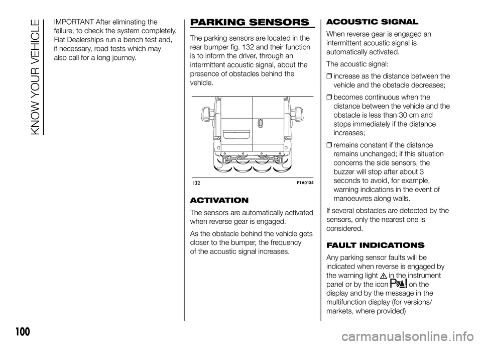
The parking sensors are located in the
rear bumper fig. 132 and their function
is to inform the driver, through an
intermittent acoustic signal, about the
presence of obstacles behind the
vehicle.
ACTIVATION
The sensors are automatically activated
when reverse gear is engaged.
As the obstacle behind the vehicle gets
closer to the bumper, the frequency
of the acoustic signal increases.ACOUSTIC SIGNAL
When reverse gear is engaged an
intermittent acoustic signal is
automatically activated.
The acoustic signal:
❒increase as the distance between the
vehicle and the obstacle decreases;
❒becomes continuous when the
distance between the vehicle and the
obstacle is less than 30 cm and
stops immediately if the distance
increases;
❒remains constant if the distance
remains unchanged; if this situation
concerns the side sensors, the
buzzer will stop after about 3
seconds to avoid, for example,
warning indications in the event of
manoeuvres along walls.
If several obstacles are detected by the
sensors, only the nearest one is
considered.
FAULT INDICATIONS
Any parking sensor faults will be
indicated when reverse is engaged by
the warning light
in the instrument
panel or by the icon
on the
display and by the message in the
multifunction display (for versions/
markets, where provided)
132F1A0134
100
KNOW YOUR VEHICLE
Page 105 of 387
OPERATION WITH
TRAILER
Parking sensor operation is
automatically deactivated when the
electric cable plug of the trailer is
inserted into the vehicle tow hook
socket.
The sensors are automatically
reactivated when the trailer's cable plug
is removed.
17)
86)
IMPORTANT If you wish to leave the
tow hook fitted without towing a trailer,
it is advisable to contact a Fiat
Dealership for the relevant system
update operations because the tow
hook could be detected as an obstacle
by the central sensors.
When using special washing equipment
such as high pressure jets or steam
cleaning, clean the sensors very quickly
keeping the jet more than 10 cm away.IMPORTANT
INFORMATION
❒Do not apply stickers to the sensors.
❒When parking, take the utmost
care over obstacles that may be
above or under the sensor.
❒Objects close to the vehicle, in
certain circumstances are not
detected and could therefore cause
damage to the vehicle or be
damaged.
The following conditions may influence
the performance of the parking
assistance system:
❒Reduced sensor sensitivity and a
reduction in the parking assistance
system performance could be due to
the presence on the surface of the
sensor of: ice, snow, mud, thick
paint.
❒The sensor may detect a non-
existent obstacle (echo noise) due to
mechanical noises, for example
when washing the vehicle, in case of
rain, strong wind, hail.
❒The signals sent by the sensors can
also be altered by the presence of
ultrasonic systems (e.g. pneumatic
brake systems or pneumatic drills)
near the vehicle.❒The performance of the parking
assistance system may also be
affected by the position of the
sensors. For example by a change in
the ride setting (caused by the wear
of the shock absorbers, suspension),
changing the tyres, overloading the
vehicle and carrying out specific
tuning operations that require the
vehicle to be lowered.
❒Detection of obstacles in the upper
part of the vehicle (particularly in the
case of vans or chassis cabs) may
not be guaranteed because the
system detects obstacles that could
strike the lower part of the vehicle.
IMPORTANT
17) The sensor must be clean of
mud, dirt, snow or ice in order for
the system to operate correctly.
Be careful not to scratch or
damage the sensors while
cleaning them. Avoid using dry,
rough or hard cloths. The sensors
must be washed using clean
water, with the addition of car
shampoo if necessary.
101
Page 106 of 387
WARNING
86) The responsibility for parking
and other dangerous manoeuvres
always and in every case lies
with the driver. While carrying out
these manoeuvres, always make
sure that no people (especially
children) or animals are in the
area concerned. The parking
sensors are used to assist the
driver, who must never allow his
attention to lapse during
potentially dangerous
manoeuvres, even those executed
at low speeds.
START&STOP
SYSTEM
IN BRIEF
The Start&Stop device automatically
stopsthe engine each time the
vehicle is stationary and starts it
again when the driver wants to move
off. This improves the efficiency of
the vehicle by reducing fuel
consumption, the emission of harmful
gases and noise pollution.
OPERATING MODES
Engine stopping mode
WITH MANUAL GEARBOX
With the vehicle stationary, the engine
stops with the gearbox in neutral and
the clutch pedal released.
NoteThe engine can only be stopped
automatically after exceeding a speed
of about 10 km/h, to prevent the engine
from being repeatedly stopped when
driving at walking pace.
Engine stopping is signalled by the
icon on the display.Engine restarting mode
WITH MANUAL GEARBOX
Depress the clutch pedal to restart the
engine.
MANUAL ACTIVATION
AND DEACTIVATION OF
THE SYSTEM
To activate/deactivate the system
manually, press the
fig. 133 button
on the dashboard control trim.
Start&Stop system
activation
A message will appear on the display
when the Start&Stop system is
activated. In this condition, the LED on
the
button is off.
Start&Stop system
deactivation
A message will appear on the display
when the Start&Stop system is
deactivated.
The LED on the
button is on when
the system is deactivated.
102
KNOW YOUR VEHICLE
Page 158 of 387
What it means What to do
FUEL CUT-OFF DEVICE INERTIA SWITCH
TRIPPED
(Versions with reconfigurable multifunction
display)
This symbol on the display switches on when the
fuel cut-off device inertia switch has tripped.For the fuel cut-off inertia switch reactivation
procedure, refer to the "Electrical power supply
and fuel cut-off switch" section in the "Knowing
your vehicle" chapter. If it is still not possible to
restore the fuel supply, contact a Fiat Dealership.
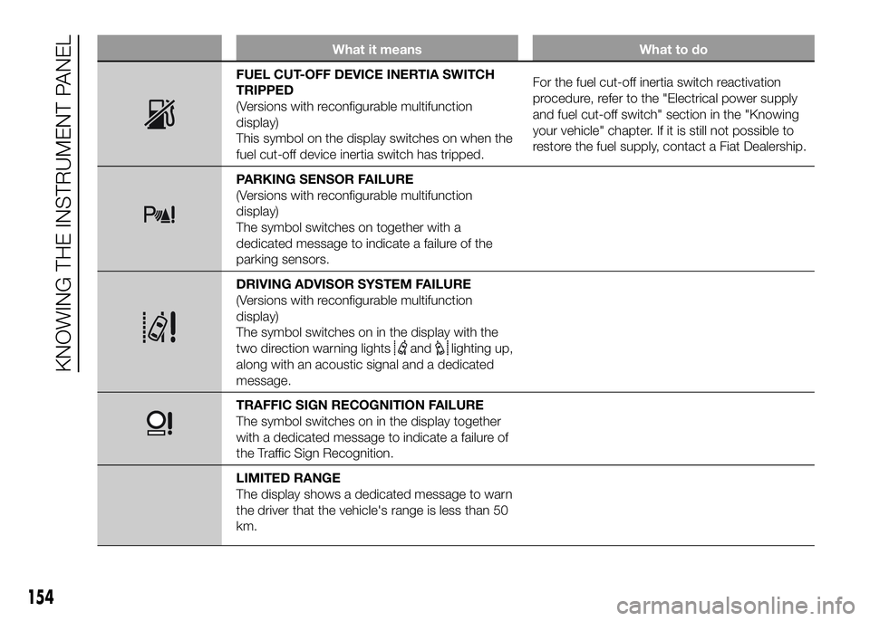
PARKING SENSOR FAILURE
(Versions with reconfigurable multifunction
display)
The symbol switches on together with a
dedicated message to indicate a failure of the
parking sensors.
DRIVING ADVISOR SYSTEM FAILURE
(Versions with reconfigurable multifunction
display)
The symbol switches on in the display with the
two direction warning lights
andlighting up,
along with an acoustic signal and a dedicated
message.
TRAFFIC SIGN RECOGNITION FAILURE
The symbol switches on in the display together
with a dedicated message to indicate a failure of
the Traffic Sign Recognition.
LIMITED RANGE
The display shows a dedicated message to warn
the driver that the vehicle's range is less than 50
km.
154
KNOWING THE INSTRUMENT PANEL
Page 194 of 387
Traffic and road
conditions
Rather high consumption levels are
linked to situations with heavy traffic, for
instance when travelling in queues
with frequent use of the lower gears or
in cities with many traffic lights. Winding
mountain roads and rough road
surfaces also adversely affect
consumption.
Stops in traffic
During prolonged hold-ups (e.g. level
crossings) the engine should be
switched off.TOWING TRAILERS
IMPORTANT
INFORMATION
The vehicle must be provided with a
type-approved tow hook and adequate
electrical system to tow caravans or
trailers. Installation should be carried
out by specialised personnel who
will issue the required papers for
travelling on roads.
Install any specific and/or additional
door mirrors as specified by the
Highway Code.
Remember that when towing a trailer,
steep hills are harder to climb, the
braking spaces increase and overtaking
takes longer depending on the overall
weight.
Engage a low gear when driving
downhill, rather than constantly using
the brake.
The weight of the trailer on the vehicle
tow hook will reduce the loading
capacity of the vehicle by the same
amount. Consider the weight of the
trailer fully laden, including accessories
and luggage, to make sure you do
not exceed the maximum towable
weight (shown on the vehicle
registration document).Do not exceed the speed limits specific
to each country you are driving in, in
the case of vehicles towing trailers.
In any case, the top speed must not
exceed 100 km/h.
You are advised to fit a suitable
stabiliser to the trailer drawbar.
In the vehicles equipped with parking
sensors, after fitting the tow hook
malfunctioning warnings may be
displayed, as some parts (tow bar, ball
tow hook) may be within the sensor
detection range. In this case the
detection range must be adjusted or
the parking assistance function must be
deactivated.
140) 141)
INSTALLING THE TOW
HOOK
The towing device should be fastened
to the body by specialised personnel
according to any additional and/or
integrative information supplied by the
Manufacturer of the device.
The towing device must meet current
regulations with reference to Directive
94/20/EC and subsequent
amendments.
For any version the towing device used
must match the towable weight of the
vehicle on which it is to be installed.
190
STARTING AND DRIVING
Page 385 of 387
Parking sensors ............................. 100
Performance .................................. 284
Pollen filter ..................................... 250
Power socket ................................. 67
Power steering fluid........................ 247
Power supply ................................. 267
Prescriptions for handling the
vehicle at the end of its life ........... 360
Pretensioners ................................. 161
Prolonged vehicle inactivity............. 199
Protecting the environment ............ 113
Radio ............................................ 106
Rain sensor .................................... 53
Rear camera .................................. 96
Rear door with two wings............... 74
Rear fog lights ................................ 60
Rear footboard ............................... 75
Rear partition ................................. 65
Rear roof light (changing a bulb) ..... 221
Rear view mirrors ........................... 25
Refrigerated compartment ............. 63
Refuelling the vehicle ...................... 109
Replacing an exterior bulb .............. 216
Replacing a wheel .......................... 203
Replacing the windscreen wiper
blades .......................................... 256
Rev counter ................................... 120
Revolving seat with seat belts ........ 18
Rim Protector................................. 271
Rims and tyres ............................... 270Roof lights...................................... 58
Roof rack ....................................... 79
Rubber hoses ................................ 255
Saving fuel .................................... 188
SBR system ................................... 161
Seat base plastic covers ................ 20
Seat belts
– Use ........................................... 160
Seats (Combi versions)................... 21
Seats ............................................. 16
Seats (Panorama version)............... 20
Seats with adjustable armrests....... 17
Seat with revolving base................. 18
Setup for Isofix child restraint
system ......................................... 168
Shelf above cab ............................. 67
Side bags....................................... 179
Side lights ......................... 48-217-221
Ski rack.......................................... 79
Sliding door.................................... 73
Sliding side window ....................... 73
Snow chains .................................. 198
Snow tyres ..................................... 198
Spare wheel ................................... 270
Speed block................................... 69
Speed Limiter................................. 56
Speedometer ................................. 120
Spray nozzles................................. 256
Sprung seat ................................... 17Starting the engine ................. 184-202
Start&Stop system ......................... 102
Steering ......................................... 269
Steering wheel ............................... 25
Stopping the engine ....................... 184
Sun visors ...................................... 66
Supplies ......................................... 327
Suspension .................................... 268
Symbols......................................... 11
Tablet Holder ................................ 67
Tachograph .................................... 68
third brake lights ............................ 220
Towing the vehicle .......................... 233
Towing trailers ................................ 190
TPMS............................................. 87
Traction Plus system ...................... 86
Transmission .................................. 268
Tray under the seat ........................ 19
Trip Computer ................................ 131
Tyres .............................................. 270
Upper storage compartment......... 63
Usage conditions ........................... 189
VIN plate ....................................... 262
Warming up the engine just
after it has started ........................ 184
Warning lights and messages......... 134
Weights.......................................... 286
Wheel geometry ............................. 270