warning FIAT DUCATO BASE CAMPER 2016 Owner handbook (in English)
[x] Cancel search | Manufacturer: FIAT, Model Year: 2016, Model line: DUCATO BASE CAMPER, Model: FIAT DUCATO BASE CAMPER 2016Pages: 387, PDF Size: 20.76 MB
Page 28 of 387
15) When refitting the bench, ensure
that it is correctly locked to the
floor guides.
IMPORTANT
2) The fabric upholstery of your
vehicle is designed to withstand
the normal wear and tear of your
vehicle for a long time. You are
however recommended to avoid
strong and/or continuous
scratching with clothing
accessories such as metal
buckles, studs, Velcro fastenings
and the like, as these items cause
stress of the cover fabric that
could lead to yarn breaking and
damage the upholstery.
HEAD RESTRAINTS
FRONT
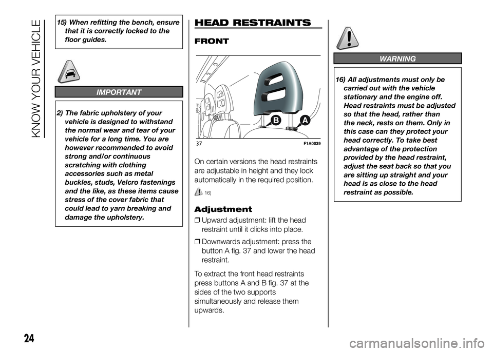
On certain versions the head restraints
are adjustable in height and they lock
automatically in the required position.
16)
Adjustment
❒Upward adjustment: lift the head
restraint until it clicks into place.
❒Downwards adjustment: press the
button A fig. 37 and lower the head
restraint.
To extract the front head restraints
press buttons A and B fig. 37 at the
sides of the two supports
simultaneously and release them
upwards.
WARNING
16) All adjustments must only be
carried out with the vehicle
stationary and the engine off.
Head restraints must be adjusted
so that the head, rather than
the neck, rests on them. Only in
this case can they protect your
head correctly. To take best
advantage of the protection
provided by the head restraint,
adjust the seat back so that you
are sitting up straight and your
head is as close to the head
restraint as possible.
37F1A0039
24
KNOW YOUR VEHICLE
Page 29 of 387
STEERING WHEEL
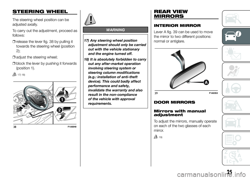
The steering wheel position can be
adjusted axially.
To carry out the adjustment, proceed as
follows:
❒release the lever fig. 38 by pulling it
towards the steering wheel (position
2);
❒adjust the steering wheel;
❒block the lever by pushing it forwards
(position 1).
17) 18)
WARNING
17) Any steering wheel position
adjustment should only be carried
out with the vehicle stationary
and the engine turned off.
18) It is absolutely forbidden to carry
out any after-market operation
involving steering system or
steering column modifications
(e.g.: installation of anti-theft
device). This could badly affect
performance and safety,
invalidate the warranty and also
result in the non-compliance
of the vehicle with approval
requirements.
REAR VIEW
MIRRORS
INTERIOR MIRROR
Lever A fig. 39 can be used to move
the mirror to two different positions:
normal or antiglare.
DOOR MIRRORS
Mirrors with manual
adjustment
To adjust the mirrors, manually operate
on each of the two glasses of each
mirror.
19)
38F1A0040
39F1A0353
25
Page 31 of 387
Manual folding
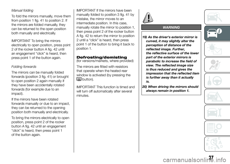
To fold the mirrors manually, move them
from position 1 fig. 41 to position 2. If
the mirrors are folded manually, they
can be returned to the open position
both manually and electrically.
IMPORTANT To bring the mirrors
electrically to open position, press point
2 of the rocker button A fig. 42 until
an engagement “click” is heard, then
press point 1 of the button again.
Folding forwards
The mirrors can be manually folded
forwards (position 3 fig. 41) or brought
to open position 2 again manually if
they have been accidentally rotated
forwards (for example due to an
impact).
If the mirrors have been rotated
forwards manually or due to an impact,
they can be returned to the opening
position both manually and electrically.
To bring the mirrors electrically to open
position, press point 2 of the rocker
button A fig. 42 until an engagement
“click” is heard, then press point 1
of the button again.IMPORTANT If the mirrors have been
manually folded to position 3 fig. 41 by
mistake, the mirror moves to an
intermediate position. In this case,
manually rotate the mirror to position 1,
then press point 2 of the rocker button
A fig. 42 to return the mirror to position
2 until a “click” is heard, then press
point 1 of the button to bring it back to
position 1.
Defrosting/demisting
(for versions/markets, where provided)
The mirrors are fitted with resistors
that operate when the heated rear
window is activated (by pressing the
button).
IMPORTANT This function is timed and
will turn off automatically after several
minutes.
WARNING
19) As the driver's exterior mirror is
curved, it may slightly alter the
perception of distance of the
reflected image. Further,
the reflective surface of the lower
part of the exterior mirrors is
parabolic to increase the field of
view. The reflected image size
is thus reduced and gives the
impression that the reflected item
is further away than it actually
is.
20) When driving the mirrors should
always remain in position 1.
27
Page 47 of 387
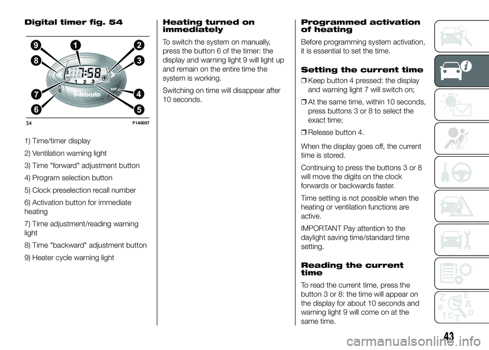
Digital timer fig. 54
1) Time/timer display
2) Ventilation warning light
3) Time "forward" adjustment button
4) Program selection button
5) Clock preselection recall number
6) Activation button for immediate
heating
7) Time adjustment/reading warning
light
8) Time "backward" adjustment button
9) Heater cycle warning lightHeating turned on
immediately
To switch the system on manually,
press the button 6 of the timer: the
display and warning light 9 will light up
and remain on the entire time the
system is working.
Switching on time will disappear after
10 seconds.Programmed activation
of heating
Before programming system activation,
it is essential to set the time.
Setting the current time
❒Keep button 4 pressed: the display
and warning light 7 will switch on;
❒At the same time, within 10 seconds,
press buttons 3 or 8 to select the
exact time;
❒Release button 4.
When the display goes off, the current
time is stored.
Continuing to press the buttons 3 or 8
will move the digits on the clock
forwards or backwards faster.
Time setting is not possible when the
heating or ventilation functions are
active.
IMPORTANT Pay attention to the
daylight saving time/standard time
setting.
Reading the current
time
To read the current time, press the
button 3 or 8: the time will appear on
the display for about 10 seconds and
warning light 9 will come on at the
same time.
54F1A0057
43
Page 48 of 387
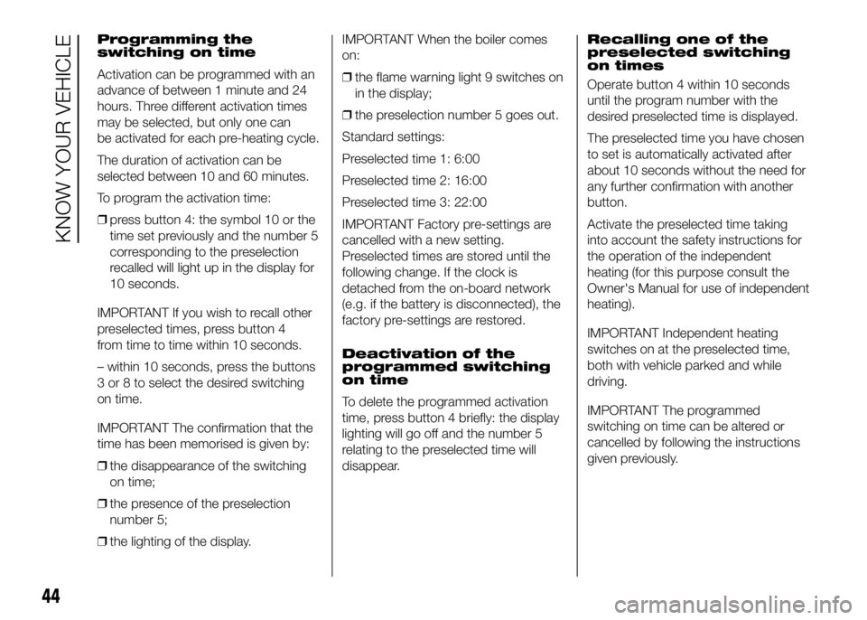
Programming the
switching on time
Activation can be programmed with an
advance of between 1 minute and 24
hours. Three different activation times
may be selected, but only one can
be activated for each pre-heating cycle.
The duration of activation can be
selected between 10 and 60 minutes.
To program the activation time:
❒press button 4: the symbol 10 or the
time set previously and the number 5
corresponding to the preselection
recalled will light up in the display for
10 seconds.
IMPORTANT If you wish to recall other
preselected times, press button 4
from time to time within 10 seconds.
– within 10 seconds, press the buttons
3 or 8 to select the desired switching
on time.
IMPORTANT The confirmation that the
time has been memorised is given by:
❒the disappearance of the switching
on time;
❒the presence of the preselection
number 5;
❒the lighting of the display.IMPORTANT When the boiler comes
on:
❒the flame warning light 9 switches on
in the display;
❒the preselection number 5 goes out.
Standard settings:
Preselected time 1: 6:00
Preselected time 2: 16:00
Preselected time 3: 22:00
IMPORTANT Factory pre-settings are
cancelled with a new setting.
Preselected times are stored until the
following change. If the clock is
detached from the on-board network
(e.g. if the battery is disconnected), the
factory pre-settings are restored.
Deactivation of the
programmed switching
on time
To delete the programmed activation
time, press button 4 briefly: the display
lighting will go off and the number 5
relating to the preselected time will
disappear.Recalling one of the
preselected switching
on times
Operate button 4 within 10 seconds
until the program number with the
desired preselected time is displayed.
The preselected time you have chosen
to set is automatically activated after
about 10 seconds without the need for
any further confirmation with another
button.
Activate the preselected time taking
into account the safety instructions for
the operation of the independent
heating (for this purpose consult the
Owner's Manual for use of independent
heating).
IMPORTANT Independent heating
switches on at the preselected time,
both with vehicle parked and while
driving.
IMPORTANT The programmed
switching on time can be altered or
cancelled by following the instructions
given previously.
44
KNOW YOUR VEHICLE
Page 49 of 387
Operation duration
setting
Hold the button pressed. At the same
time press button 3 or 8.
The time and warning light 7 are
displayed.
Hold button 4 pressed again. At the
same time press button 3 or 8.
The preset activation duration is
displayed and warning light 9 or 2
flashes.
Set the activation duration with button
3or8.
The set activation duration is stored as
soon as the text in the display
disappears, or pressing button 4.Switching the heating
system off
Deactivation of the system, depending
on the type of activation (automatic
or manual), may be:
❒automaticwhen the programmed
duration is over; when the set time
is over, the display switches off.
❒manualpressing the “immediate
heating” button on the timer again
(flame button 6).
In both cases, the heating warning light,
the display lighting and the passenger
compartment heater fan go off and
burning stops.
The fluid circulation pump continues to
work for around two minutes to
dissipate as much heat as possible; the
heater can be turned back on during
this stage.
22)
IMPORTANT The parking heater goes
off when battery voltage is low to allow
the vehicle to be started.
IMPORTANT Before turning on the
device, ensure that the fuel level is
above the reserve. Otherwise the
device could lock and require
the assistance of a Fiat Dealership.
❒Always turn off the heater when
refuelling and near service stations to
avoid the risk of explosion or fire
hazards.
❒Do not park the vehicle on
inflammable material such as paper,
grass or dry leaves: fire hazard!
❒The temperature near the heater
should not exceed 120°C (e.g. during
oven painting in a body shop). The
electronic control unit components
may be damaged at higher
temperatures.
❒Whilst the heater is operating with the
engine switched off, it absorbs
energy from the battery; the engine
should therefore be left running
for a while to make sure that the
battery is properly recharged.
45
Page 51 of 387
ADDITIONAL REAR
CLIMATE CONTROL
(Panorama and Combi)
(for versions/markets, where provided)
The Panorama and Combi versions
are equipped with a main heating/air
conditioning system plus an additional
system (available on request) with
controls in the roof lining above the
second row of seats fig. 55. Button F
fig. 56 in the control panel must be
enabled for operation; the air
conditioning only works if the main air
conditioner is on.
❒When the knob D is placed in the
fully cold position (control in blue
sector) cold air comes out the vents
in the ceiling.
❒Turn the knob D to the maximum
heating position (knob at red
sector);warm air will emerge (with the
engine warmed up), from the rear
footwell outlets (located under the
seats in the 2nd and 3rd row for
Panorama versions and the grille on
the left wheel arch side for Combi
versions).❒If the selector knob D is placed in the
intermediate positions, the air will be
distributed between the vents in
the ceiling and the rear footwell
vents, varying the temperature.
IMPORTANT If the compressor on the
main air conditioner control is turned on
(operation of button E), even if the
additional air conditioner fan is in
position 0, the 1st speed will
automatically be activated to prevent
ice formation, with possible damage to
the component.
WARNING
21) The heater burns fuel in the
same way as the engine, though
to a lesser extent. To prevent
poisoning and asphyxiation, the
additional heater must never
be turned on, not even for short
periods, in closed environments
such as a garage or workshops
without extraction fans for the
exhaust gases.22) The heater burns fuel in the
same way as the engine, though
to a lesser extent. To prevent
poisoning and asphyxiation, the
supplementary heater must never
be turned on, not even for short
periods, in closed environments
such as a garage or workshops
without extraction fans for the
exhaust gases.
47
Page 52 of 387
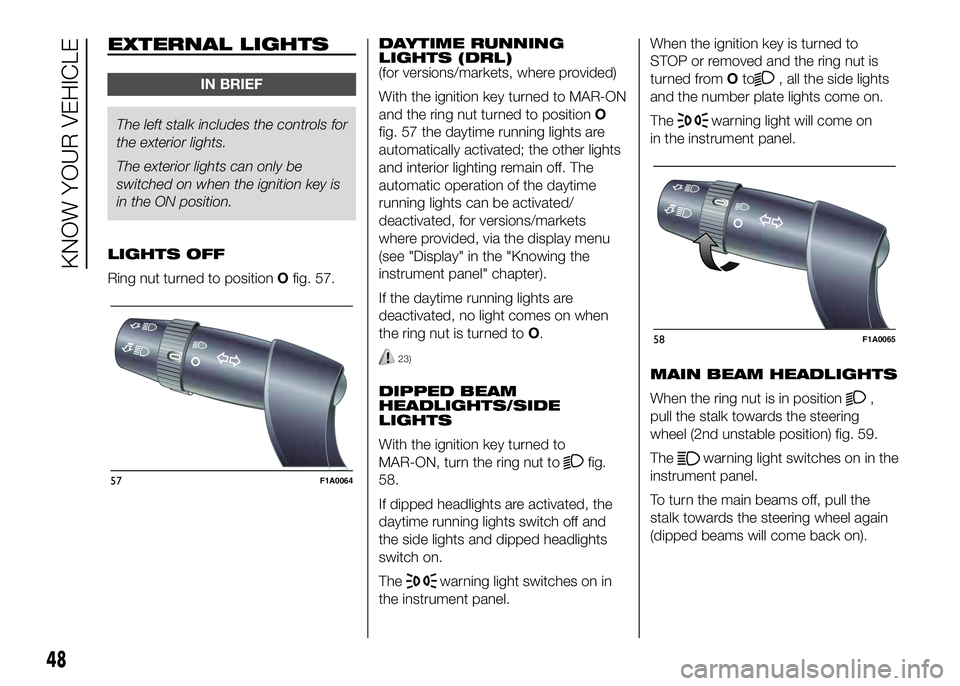
EXTERNAL LIGHTS
IN BRIEF
The left stalk includes the controls for
theexterior lights.
The exterior lights can only be
switched on when the ignition key is
in the ON position.
LIGHTS OFF
Ring nut turned to positionOfig. 57.DAYTIME RUNNING
LIGHTS (DRL)
(for versions/markets, where provided)
With the ignition key turned to MAR-ON
and the ring nut turned to positionO
fig. 57 the daytime running lights are
automatically activated; the other lights
and interior lighting remain off. The
automatic operation of the daytime
running lights can be activated/
deactivated, for versions/markets
where provided, via the display menu
(see "Display" in the "Knowing the
instrument panel" chapter).
If the daytime running lights are
deactivated, no light comes on when
the ring nut is turned toO.
23)
DIPPED BEAM
HEADLIGHTS/SIDE
LIGHTS
With the ignition key turned to
MAR-ON, turn the ring nut to
fig.
58.
If dipped headlights are activated, the
daytime running lights switch off and
the side lights and dipped headlights
switch on.
The
warning light switches on in
the instrument panel.When the ignition key is turned to
STOP or removed and the ring nut is
turned fromOto
, all the side lights
and the number plate lights come on.
The
warning light will come on
in the instrument panel.
MAIN BEAM HEADLIGHTS
When the ring nut is in position
,
pull the stalk towards the steering
wheel (2nd unstable position) fig. 59.
The
warning light switches on in the
instrument panel.
To turn the main beams off, pull the
stalk towards the steering wheel again
(dipped beams will come back on).
57F1A0064
58F1A0065
48
KNOW YOUR VEHICLE
Page 53 of 387
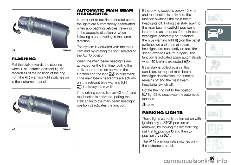
FLASHING
Pull the stalk towards the steering
wheel (1st unstable position) fig. 60
regardless of the position of the ring
nut. The
warning light switches on
in the instrument panel.AUTOMATIC MAIN BEAM
HEADLIGHTS
In order not to dazzle other road users,
the lights are automatically deactivated
when approaching vehicles travelling
in the opposite direction or when
following a car travelling in the same
direction.
The system is activated with the menu
item and by rotating the light selector to
the AUTO position.
When the main beam headlights are
activated for the first time, pulling the
stalk to turn them on activates the
function and the iconis displayed;
if the main beam headlights are actually
on, the relevant blue warning light
is displayed as well.
If the driving speed is over 40 km/h and
the function is activated, pulling the
stalk again to the main beam headlight
position deactivates the function.If the driving speed is below 15 km/h
and the function is activated, the
function switches the main beam
headlights off. Pulling the stalk again to
the main beam headlight position is
interpreted as a request for main beam
headlights constantly on, therefore
the blue warning light
on the panel
switches on and the main beam
headlights are constantly on until the
speed exceeds 40 km/h again. The
function is activated again automatically
when 40 km/h is exceeded
.
If the stalk is pulled again in this
condition, to request main beam
headlight deactivation, the function
remains off and the main beam
headlights switch off.
Rotate the ring nut to the position
fig. 58 to deactivate the automatic
function.
25) 24)
PARKING LIGHTS
These lights can only be turned on with
ignition key in STOP position or
removed, by moving the left stalk ring
nut first to positionOand then to
position
or.
The
warning light switches on in
the instrument panel.
59F1A0066
60F1A0067
49
Page 54 of 387
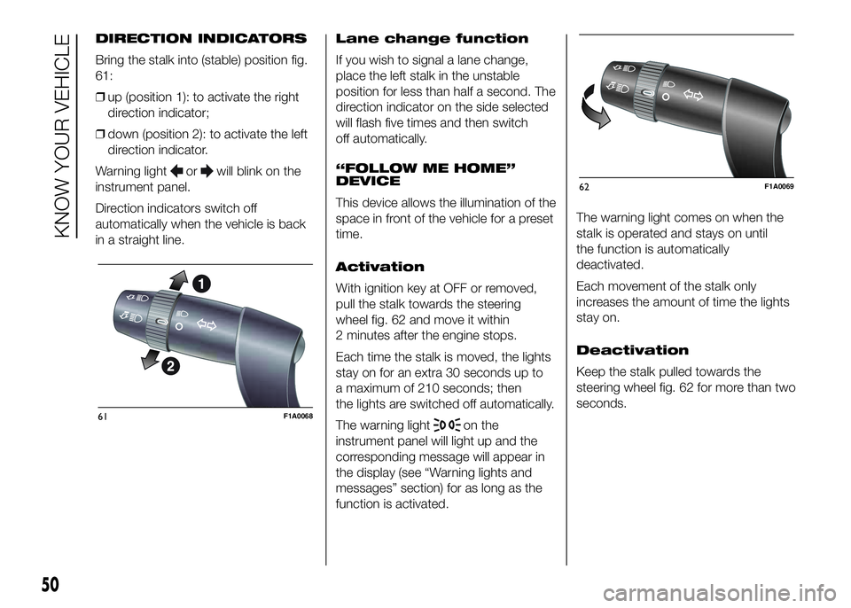
DIRECTION INDICATORS
Bring the stalk into (stable) position fig.
61:
❒up (position 1): to activate the right
direction indicator;
❒down (position 2): to activate the left
direction indicator.
Warning light
orwill blink on the
instrument panel.
Direction indicators switch off
automatically when the vehicle is back
in a straight line.Lane change function
If you wish to signal a lane change,
place the left stalk in the unstable
position for less than half a second. The
direction indicator on the side selected
will flash five times and then switch
off automatically.
“FOLLOW ME HOME”
DEVICE
This device allows the illumination of the
space in front of the vehicle for a preset
time.
Activation
With ignition key at OFF or removed,
pull the stalk towards the steering
wheel fig. 62 and move it within
2 minutes after the engine stops.
Each time the stalk is moved, the lights
stay on for an extra 30 seconds up to
a maximum of 210 seconds; then
the lights are switched off automatically.
The warning light
on the
instrument panel will light up and the
corresponding message will appear in
the display (see “Warning lights and
messages” section) for as long as the
function is activated.The warning light comes on when the
stalk is operated and stays on until
the function is automatically
deactivated.
Each movement of the stalk only
increases the amount of time the lights
stay on.
Deactivation
Keep the stalk pulled towards the
steering wheel fig. 62 for more than two
seconds.61F1A0068
62F1A0069
50
KNOW YOUR VEHICLE