warning FIAT DUCATO BASE CAMPER 2016 Owner handbook (in English)
[x] Cancel search | Manufacturer: FIAT, Model Year: 2016, Model line: DUCATO BASE CAMPER, Model: FIAT DUCATO BASE CAMPER 2016Pages: 387, PDF Size: 20.76 MB
Page 55 of 387
AUTOMATIC HEADLIGHT
SENSOR (dusk sensor)
(for versions/markets, where provided)
It detects variations in brightness
outside the vehicle depending on the
light sensitivity setting: the greater
the sensitivity, the less outside light
needed to activate the exterior lights.
The sensitivity of the dusk sensor is
adjusted by means of the "Setup
menu" of the display.
Activation
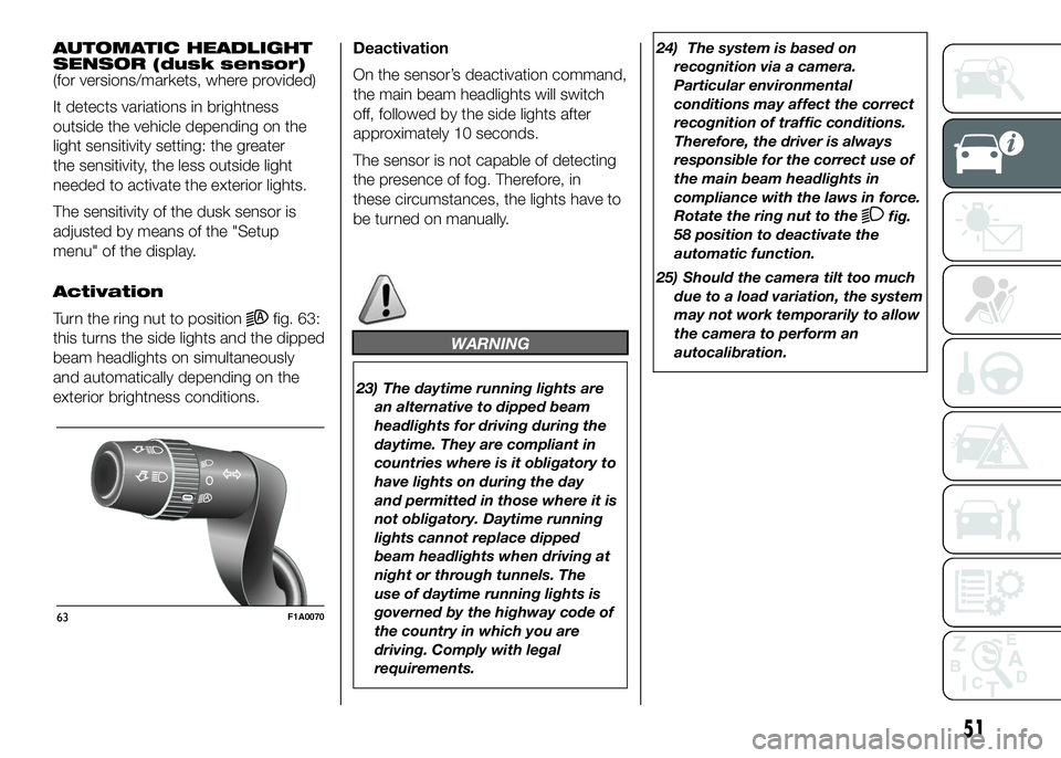
Turn the ring nut to position
fig. 63:
this turns the side lights and the dipped
beam headlights on simultaneously
and automatically depending on the
exterior brightness conditions.Deactivation
On the sensor’s deactivation command,
the main beam headlights will switch
off, followed by the side lights after
approximately 10 seconds.
The sensor is not capable of detecting
the presence of fog. Therefore, in
these circumstances, the lights have to
be turned on manually.
WARNING
23) The daytime running lights are
an alternative to dipped beam
headlights for driving during the
daytime. They are compliant in
countries where is it obligatory to
have lights on during the day
and permitted in those where it is
not obligatory. Daytime running
lights cannot replace dipped
beam headlights when driving at
night or through tunnels. The
use of daytime running lights is
governed by the highway code of
the country in which you are
driving. Comply with legal
requirements.24) The system is based on
recognition via a camera.
Particular environmental
conditions may affect the correct
recognition of traffic conditions.
Therefore, the driver is always
responsible for the correct use of
the main beam headlights in
compliance with the laws in force.
Rotate the ring nut to the
fig.
58 position to deactivate the
automatic function.
25) Should the camera tilt too much
due to a load variation, the system
may not work temporarily to allow
the camera to perform an
autocalibration.
63F1A0070
51
Page 58 of 387
WARNING
26) Streaks of water may cause
unnecessary blade movements.
CRUISE CONTROL
(for versions/markets, where provided)
IN BRIEF
This is an electronic driving aid that
allowsyou to drive at a speed of
above 30 km/h on long and straight
dry roads with few driving changes
(e.g. motorways) at a preset speed
without having to press the
accelerator pedal. It is therefore not
recommended to use this device
on extra-urban roads with traffic. Do
not use it in town.
Switching the device on
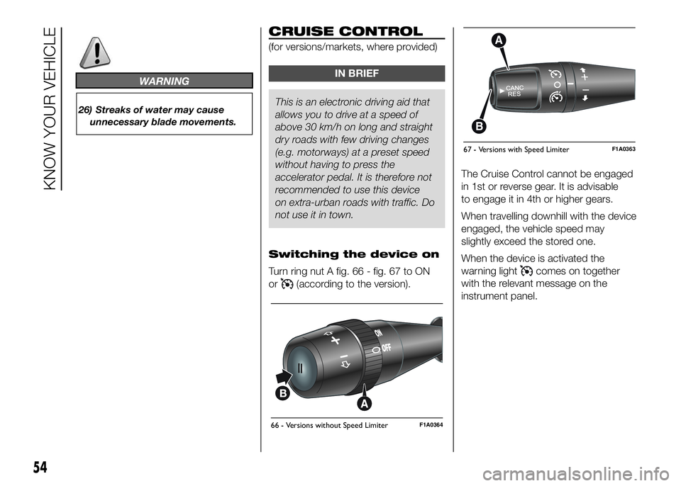
Turn ring nut A fig. 66 - fig. 67 to ON
or
(according to the version).The Cruise Control cannot be engaged
in 1st or reverse gear. It is advisable
to engage it in 4th or higher gears.
When travelling downhill with the device
engaged, the vehicle speed may
slightly exceed the stored one.
When the device is activated the
warning light
comes on together
with the relevant message on the
instrument panel.
66 - Versions without Speed LimiterF1A0364
67 - Versions with Speed LimiterF1A0363
54
KNOW YOUR VEHICLE
Page 60 of 387
❒by pressing the accelerator pedal; in
this case the system is not actually
turned off but the acceleration
request takes priority; the Cruise
Control remains activated, without
the need to press the CANC/RES
button to restore the previous
conditions once the acceleration is
over.
The device is automatically switched off
in the following cases:
❒if the ABS or ESP systems cut in;
❒in the event of system failure.
27) 28)
SPEED LIMITER
This device allows the speed of the car
to be limited to values which can be
set by the driver.
The maximum speed can be set both
with vehicle stationary and in motion.
The minimum speed that can be set is
30 km/h.
When the device is active, the car
speed depends on the pressure at the
accelerator pedal, until the
programmed speed limit is reached
(see "Speed limit programming"
paragraph).If necessary (in the event of overtaking
for example), the set speed limit can
be exceeded by fully depressing the
accelerator pedal.
By gradually reducing the pressure on
the accelerator pedal, the function
will be reactivated as soon as the car
speed drops below the set speed.
Switching the device on
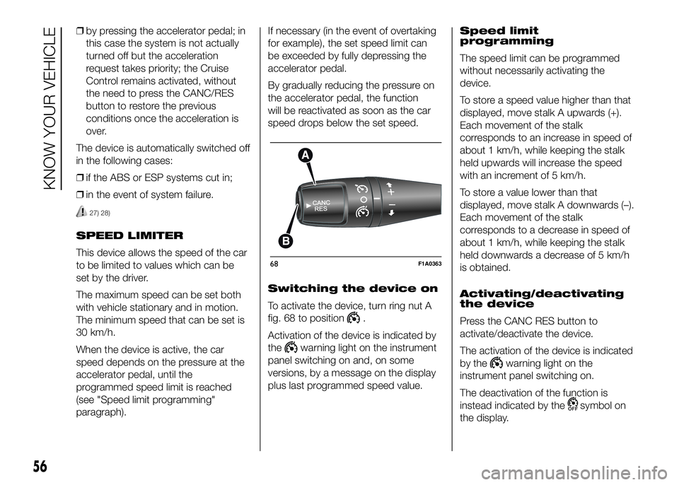
To activate the device, turn ring nut A
fig. 68 to position
.
Activation of the device is indicated by
the
warning light on the instrument
panel switching on and, on some
versions, by a message on the display
plus last programmed speed value.Speed limit
programming
The speed limit can be programmed
without necessarily activating the
device.
To store a speed value higher than that
displayed, move stalk A upwards (+).
Each movement of the stalk
corresponds to an increase in speed of
about 1 km/h, while keeping the stalk
held upwards will increase the speed
with an increment of 5 km/h.
To store a value lower than that
displayed, move stalk A downwards (–).
Each movement of the stalk
corresponds to a decrease in speed of
about 1 km/h, while keeping the stalk
held downwards a decrease of 5 km/h
is obtained.
Activating/deactivating
the device
Press the CANC RES button to
activate/deactivate the device.
The activation of the device is indicated
by the
warning light on the
instrument panel switching on.
The deactivation of the function is
instead indicated by the
symbol on
the display.
68F1A0363
56
KNOW YOUR VEHICLE
Page 61 of 387
Exceeding the
programmed speed
By fully depressing the accelerator
pedal, the programmed speed can be
exceeded even with the device active.
IMPORTANT A slight hardening of
the accelerator pedal is perceived when
the end of travel is reached. This is to
intentionally signal to the driver that the
speed control system is being
deactivated.
When the programmed speed limit is
reached by fully depressing the
accelerator pedal, it is normal to
perceive increased resistance on the
pedal itself.
In this case the device is deactivated
temporarily and the set speed flashes
on the display.
Reducing the speed below the
programmed value reactivates the
device automatically.
IMPORTANT With the device
deactivated, the car maximum speed is
reached before the end of travel with
the load hardening.Flashing of programmed
speed
The programmed speed flashes in the
following cases:
❒when the accelerator pedal has been
fully depressed and the car speed
has exceeded programmed speed;
❒when the device cannot reduce the
speed of the car due to the gradient
of the road;
❒in the event of sharp acceleration.
Deactivating the device
To deactivate the device, turn ring nut A
toO.
The deactivation of the device is
indicated by the
warning light
switching off on the instrument panel
and, on some versions, by a message
and
symbol on the display.
Automatic deactivation
of device
The device deactivates automatically in
the event of fault in the system.
WARNING
27) When travelling with the device
active, never move the gear lever
to neutral.
28) If the device is faulty, turn ring
nutAtoO, check the condition
of the fuse and contact a Fiat
Dealership.
57
Page 63 of 387
LOAD COMPARTMENT
SIDE COURTESY LIGHT
(for versions/markets, where provided)
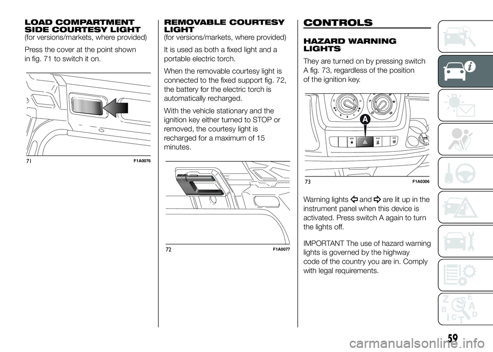
Press the cover at the point shown
in fig. 71 to switch it on.REMOVABLE COURTESY
LIGHT
(for versions/markets, where provided)
It is used as both a fixed light and a
portable electric torch.
When the removable courtesy light is
connected to the fixed support fig. 72,
the battery for the electric torch is
automatically recharged.
With the vehicle stationary and the
ignition key either turned to STOP or
removed, the courtesy light is
recharged for a maximum of 15
minutes.CONTROLS
HAZARD WARNING
LIGHTS
They are turned on by pressing switch
A fig. 73, regardless of the position
of the ignition key.
Warning lights
andare lit up in the
instrument panel when this device is
activated. Press switch A again to turn
the lights off.
IMPORTANT The use of hazard warning
lights is governed by the highway
code of the country you are in. Comply
with legal requirements.
71F1A0076
72F1A0077
73F1A0306
59
Page 64 of 387
Emergency braking
(for versions/markets, where provided)
In the event of emergency braking
the hazard warning lights come on
automatically, as do the
and
warning lights in the panel. The
function switches off automatically
when the nature of the braking
changes. This function complies with
the relevant legislation currently in force.
FOG LIGHTS
(for versions/markets, where provided)
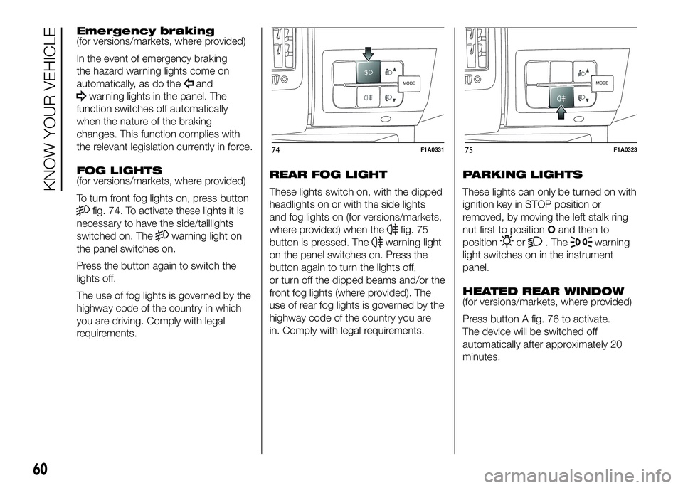
To turn front fog lights on, press button
fig. 74. To activate these lights it is
necessary to have the side/taillights
switched on. The
warning light on
the panel switches on.
Press the button again to switch the
lights off.
The use of fog lights is governed by the
highway code of the country in which
you are driving. Comply with legal
requirements.REAR FOG LIGHT
These lights switch on, with the dipped
headlights on or with the side lights
and fog lights on (for versions/markets,
where provided) when thefig. 75
button is pressed. The
warning light
on the panel switches on. Press the
button again to turn the lights off,
or turn off the dipped beams and/or the
front fog lights (where provided). The
use of rear fog lights is governed by the
highway code of the country you are
in. Comply with legal requirements.PARKING LIGHTS
These lights can only be turned on with
ignition key in STOP position or
removed, by moving the left stalk ring
nut first to positionOand then to
positionor. Thewarning
light switches on in the instrument
panel.
HEATED REAR WINDOW
(for versions/markets, where provided)
Press button A fig. 76 to activate.
The device will be switched off
automatically after approximately 20
minutes.
MODE
74F1A0331
MODE
75F1A0323
60
KNOW YOUR VEHICLE
Page 66 of 387
.
FUEL CUT-OFF
SWITCH
The vehicle is fitted with a safety switch
that, in the event of a crash, comes
into operation by cutting off the fuel
supply and turning off the engine as a
consequence.
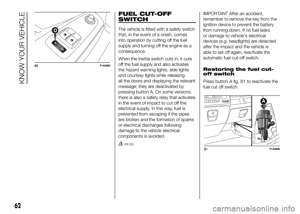
When the inertia switch cuts in, it cuts
off the fuel supply and also activates
the hazard warning lights, side lights
and courtesy lights while releasing
all the doors and displaying the relevant
message; they are deactivated by
pressing button A. On some versions,
there is also a safety relay that activates
in the event of impact to cut off the
electrical supply. In this way, fuel is
prevented from escaping if the pipes
are broken and the formation of sparks
or electrical discharges following
damage to the vehicle electrical
components is avoided.
29) 30)
IMPORTANT After an accident,
remember to remove the key from the
ignition device to prevent the battery
from running down. If no fuel leaks
or damage to vehicle's electrical
devices (e.g. headlights) are detected
after the impact and the vehicle is
able to set off again, reactivate the
automatic fuel cut-off switch.
Restoring the fuel cut-
off switch
Press button A fig. 81 to reactivate the
fuel cut off switch.
80F1A0085
81F1A0086
62
KNOW YOUR VEHICLE
Page 67 of 387
WARNING
29) If, after an impact, you smell fuel
or notice leaks from the fuel
system, do not reactivate the
switch to avoid the risk of fire.
30) Before reactivating the fuel
cut-off switch, carefully check for
fuel leaks or damage to the
vehicle's electrical devices (e.g.
headlights).
INTERIOR FITTINGS
UPPER STORAGE
COMPARTMENT -
REFRIGERATED
COMPARTMENT
(for versions/markets, where provided)
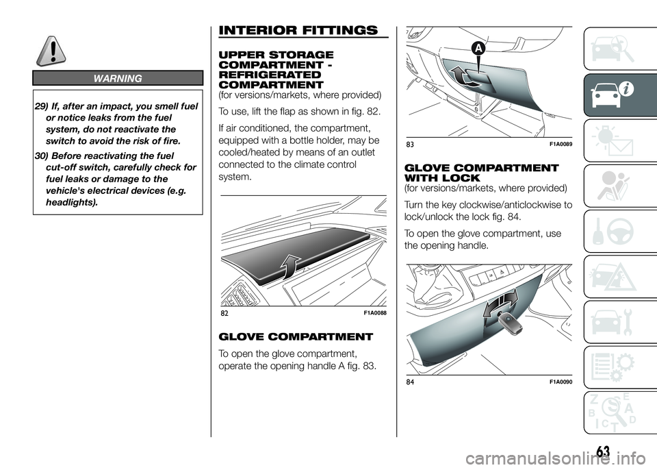
To use, lift the flap as shown in fig. 82.
If air conditioned, the compartment,
equipped with a bottle holder, may be
cooled/heated by means of an outlet
connected to the climate control
system.
GLOVE COMPARTMENT
To open the glove compartment,
operate the opening handle A fig. 83.GLOVE COMPARTMENT
WITH LOCK
(for versions/markets, where provided)
Turn the key clockwise/anticlockwise to
lock/unlock the lock fig. 84.
To open the glove compartment, use
the opening handle.
82F1A0088
83F1A0089
84F1A0090
63
Page 72 of 387
CAB GLOVE
COMPARTMENT
(CAPUCINE)
(for versions/markets, where provided)
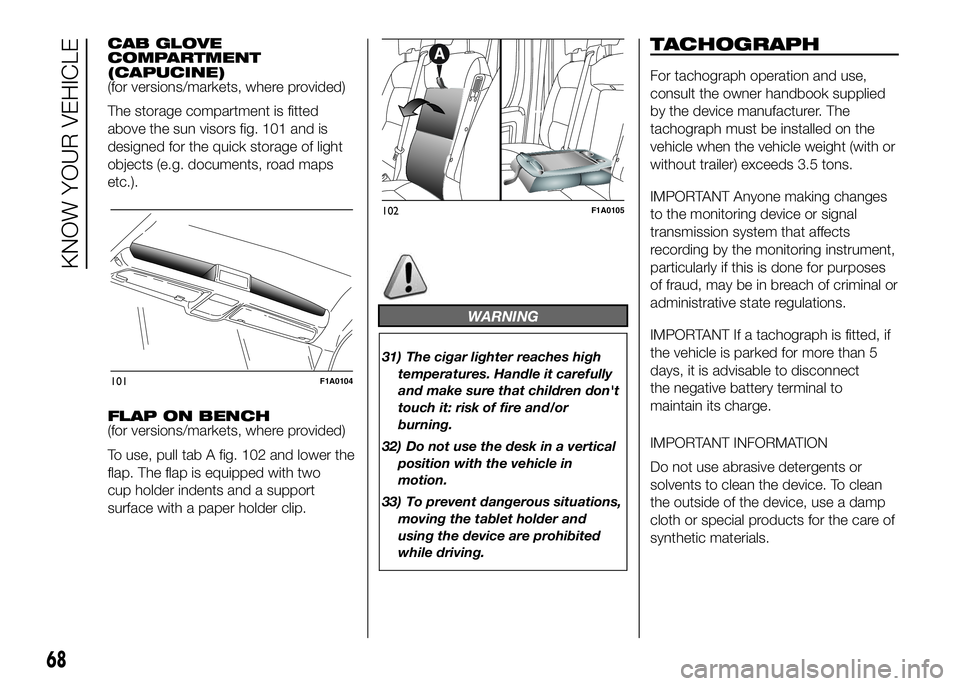
The storage compartment is fitted
above the sun visors fig. 101 and is
designed for the quick storage of light
objects (e.g. documents, road maps
etc.).
FLAP ON BENCH
(for versions/markets, where provided)
To use, pull tab A fig. 102 and lower the
flap. The flap is equipped with two
cup holder indents and a support
surface with a paper holder clip.
WARNING
31) The cigar lighter reaches high
temperatures. Handle it carefully
and make sure that children don't
touch it: risk of fire and/or
burning.
32) Do not use the desk in a vertical
position with the vehicle in
motion.
33) To prevent dangerous situations,
moving the tablet holder and
using the device are prohibited
while driving.
TACHOGRAPH
For tachograph operation and use,
consult the owner handbook supplied
by the device manufacturer. The
tachograph must be installed on the
vehicle when the vehicle weight (with or
without trailer) exceeds 3.5 tons.
IMPORTANT Anyone making changes
to the monitoring device or signal
transmission system that affects
recording by the monitoring instrument,
particularly if this is done for purposes
of fraud, may be in breach of criminal or
administrative state regulations.
IMPORTANT If a tachograph is fitted, if
the vehicle is parked for more than 5
days, it is advisable to disconnect
the negative battery terminal to
maintain its charge.
IMPORTANT INFORMATION
Do not use abrasive detergents or
solvents to clean the device. To clean
the outside of the device, use a damp
cloth or special products for the care of
synthetic materials.
101F1A0104
102F1A0105
68
KNOW YOUR VEHICLE
Page 75 of 387
DOORS
DOOR CENTRAL
LOCKING/UNLOCKING
Locking doors from the
outside
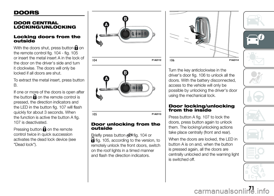
With the doors shut, press button
on
the remote control fig. 104 - fig. 105
or insert the metal insert A in the lock of
the door on the driver's side and turn
it clockwise. The doors will only be
locked if all doors are shut.
To extract the metal insert, press button
B.
If one or more of the doors is open after
the button
on the remote control is
pressed, the direction indicators and
the LED in the button fig. 107 will flash
quickly for about 3 seconds. When
the function is active the button A fig.
107 is deactivated.
Pressing button
on the remote
control twice in quick succession
activates the dead lock device (see
"Dead lock").Door unlocking from the
outside
Briefly press button
fig. 104 or
fig. 105, according to the version, to
remotely unlock the front doors, switch
on the roof lights in a timed manner
and flash the direction indicators.Turn the key anticlockwise in the
driver's door fig. 106 to unlock all the
doors. With the battery disconnected,
access to the vehicle will only be
possible by unlocking the driver's door
using the mechanical lock.
Door locking/unlocking
from the inside
Press button A fig. 107 to lock the
doors, press button again to unlock
them. The locking/unlocking actions
take place centrally (front and rear).
When the doors are locked, the LED in
button A is on and, when the button
is pressed again, all the doors are
centrally unlocked and the warning light
is switched off.
104F1A0112
105F1A0113
106F1A0114
71