trip computer FIAT DUCATO BASE CAMPER 2016 Owner handbook (in English)
[x] Cancel search | Manufacturer: FIAT, Model Year: 2016, Model line: DUCATO BASE CAMPER, Model: FIAT DUCATO BASE CAMPER 2016Pages: 387, PDF Size: 20.76 MB
Page 119 of 387
KNOWING THE INSTRUMENT PANEL
This section of the booklet gives you all
the information you need to
understand, interpret and use the
instrument panel correctly.CONTROL PANEL AND
INSTRUMENTS ...............................116
DISPLAY ........................................122
TRIP COMPUTER ...........................131
WARNING LIGHTS AND
MESSAGES ....................................134
- LOW BRAKE FLUID/HANDBRAKE
ENGAGED .......................................... 134
- EBD FAILURE .................................. 135
- AIRBAG FAILURE ............................. 135
- SEAT BELTS NOT FASTENED .......... 136
- ENGINE COOLANT TEMPERATURE
TOO HIGH .......................................... 137
- LOW BATTERY CHARGE ................. 137
- LOW ENGINE OIL PRESSURE ......... 138
-ENGINE OIL DETERIORATED ........... 138
-INCOMPLETE DOOR/LOAD
COMPARTMENT CLOSURE ............... 139
- POWER STEERING FAILURE ........... 139
-SELF-LEVELLING SUSPENSION
FAILURE ............................................. 139
- INJECTION/EOBD SYSTEM
FAILURE ............................................. 141
-UREA INJECTION SYSTEM FAILURE
............................................................ 142
- ABS FAILURE ................................... 142
-FUEL RESERVE ................................ 143
-GLOW PLUG PREHEATING / GLOW
PLUG PREHEATING FAILURE ............ 143
-INDICATION OF DIESEL EMISSIONS
ADDITIVE LOW LEVEL (UREA) ........... 144
-VEHICLE PROTECTION SYSTEM
FAILURE - FIAT CODE ........................ 144
- REAR FOG LIGHTS .......................... 144
- GENERAL FAILURE INDICATION ..... 145
-DPF (PARTICULATE FILTER)
CLEANING UNDERWAY ..................... 146
-WORN BRAKE PADS ........................ 147-DRIVING ADVISOR ........................... 147
- TPMS ............................................... 148
- DIPPED HEADLIGHTS ..................... 149
- FOLLOW ME HOME ........................ 149
- LEFT-HAND DIRECTION INDICATOR
............................................................ 149
- RIGHT-HAND DIRECTION
INDICATOR ........................................ 150
-FOG LIGHTS ..................................... 150
- CRUISE CONTROL .......................... 150
-SPEED LIMITER ................................ 150
- AUTOMATIC MAIN BEAM
HEADLIGHTS ..................................... 151
- MAIN BEAM HEADLIGHTS .............. 151
-"UP" FUNCTION ............................... 151
-EXTERIOR LIGHTS FAULT ................ 152
-BRAKE LIGHT FAILURE .................... 152
-MAIN BEAM AUTOMATISM FAULT ... 153
-POSSIBLE ICE ON ROAD ................. 153
-SPEED LIMIT EXCEEDED ................. 153
-SCHEDULED SERVICING ................. 153
-FUEL CUT-OFF DEVICE INERTIA
SWITCH TRIPPED .............................. 154
-PARKING SENSOR FAILURE ............ 154
-DRIVING ADVISOR SYSTEM
FAILURE ............................................. 154
-TRAFFIC SIGN RECOGNITION
FAILURE ............................................. 154
-LIMITED RANGE ............................... 154
-START&STOP SYSTEM
ACTIVATION/DEACTIVATION .............. 155
-START&STOP FAILURE .................... 155
-INDICATION OF DIESEL EMISSIONS
ADDITIVE LOW LEVEL (UREA) ........... 156
-WATER IN DIESEL FILTER (diesel
versions) ............................................. 156
115
Page 130 of 387
Headlight sensor
sensitivity adjustment
(for versions/markets, where provided)
With this function it is possible to adjust
the rain headlight sensitivity according
to 3 levels.
To set the required sensitivity level,
proceed as follows:
– briefly press the MODE button: the
previously set sensitivity “level” starts to
flash on the display;
– press the
orbutton to
make the adjustment;
– press the MODE button briefly to
return to the menu screen or hold the
button down to return to the standard
screen without storing.
Cornering lights
(Activation/deactivation of
“Cornering lights”)
(for versions/markets, where provided)
This function activates/deactivates
("On"/"Off") the cornering lights (see the
description in the “Exterior lights”
paragraph).
Proceed as follows to activate/
deactivate the lights:
❒briefly press the MODE button. "On"
or "Off" flash on the display,
according to what has been
previously set;❒press
orto make your
choice;
❒briefly press the MODE button to
return to the menu screen or hold the
button down to return to the
standard screen without storing.
Rain sensor
(Rain sensor setting adjustment)
(for versions/markets, where provided)
This function allows you to adjust the
rain sensor sensitivity to 4 levels.
To set the required sensitivity level,
proceed as follows:
❒briefly press the MODE button. The
sensitivity “level” set previously
flashes on the display;
❒press the
orbutton to
make the adjustment;
❒briefly press the MODE button to
return to the menu screen or hold the
button down to return to the
standard screen without storing.Trip B On/Off (Trip B
data)
This function can be used to activate
(On) or deactivate (Off) the Trip B
display (partial trip).
For more information see the "Trip
computer" paragraph.
For activation/deactivation, proceed as
follows:
- briefly press the MODE button: ON or
OFF flashes on the display (depending
the previous setting);
- press the
orbutton to
select;
- press the MODE button briefly to
return to the menu screen or hold the
button down to return to the standard
screen without storing.
Traffic sign
This function allows you to activate (On)
or deactivate (Off) the Traffic Sign
function to recognise the traffic signs
(no overtaking or speed limits).
For activation/deactivation, proceed as
follows:
- briefly press the MODE button: ON or
OFF flashes on the display (depending
the previous setting);
126
KNOWING THE INSTRUMENT PANEL
Page 135 of 387
Exit Menu
This is the last function that closes the
cycle of settings listed in the menu
screen.
Pressing the MODE button briefly will
return the display to the standard
screen without storing.
Press button
to return to the first
menu item (Speed Beep).
TRIP COMPUTER
IN BRIEF
The Trip computer is used to display
informationon vehicle operation
when the ignition key is turned to
MAR-ON. This function allows you to
define two separate trips, called
"Trip A" and "Trip B", for monitoring
the "complete mission" (journey)
of the vehicle in a reciprocally
independent manner. Both functions
can be reset (reset means start of
a new journey).
“Trip A” is used to display the figures
relating to:
❒Outside temperature
❒Range
❒Distance travelled A
❒Average consumption A
❒Instant fuel consumption
❒Average speed A
❒Trip time A (driving time).
❒Reset Trip A
"Trip B", available on multifunction
display only, is used to display
the values relating to:❒Distance travelled B
❒Average consumption B
❒Average speed B
❒Trip time B (driving time).21)
Values displayed
Outside temperature
Indicates the temperature outside the
vehicle passenger compartment.
Range (for versions/markets, where
provided)
This indicates the distance that can still
be travelled with the fuel in the tank,
assuming that driving style remains
unvaried. The display will show the
reading '-----' when the following
events take place:
❒range value lower than 50 km (or 30
mi)
❒vehicle is left parked with the engine
running for a long time.
131
Page 136 of 387
IMPORTANT The range can be affected
by several factors: driving style (see
paragraph “Driving style” in the
“Starting and driving” section), type of
route (motorway, towns and cities,
mountain roads, etc…), usage
conditions (load, tyre pressures, etc…).
Trip planning must therefore take the
above into account.
Distance travelled
This value shows the distance covered
from the start of the new journey.
Average consumption (for versions/
markets, where provided)
This value shows the approximate
average fuel consumption from the start
of the new journey.
Instant consumption (for versions/
markets where provided)
This value shows the fuel consumption.
The value is constantly updated. The
display will show “----”ifthecar
is parked with the engine running.Average speed
This value shows the car's average
speed based on the overall time
elapsed since the start of the new
journey.
Trip time
Time elapsed since the start of the new
journey.
IMPORTANT If there is no information,
the Trip computer displays "----" in
place of the value. When normal
operating conditions are restored, the
counting of the various values is
resumed, without either zeroing the
values displayed prior to the problem,
or starting a new mission.
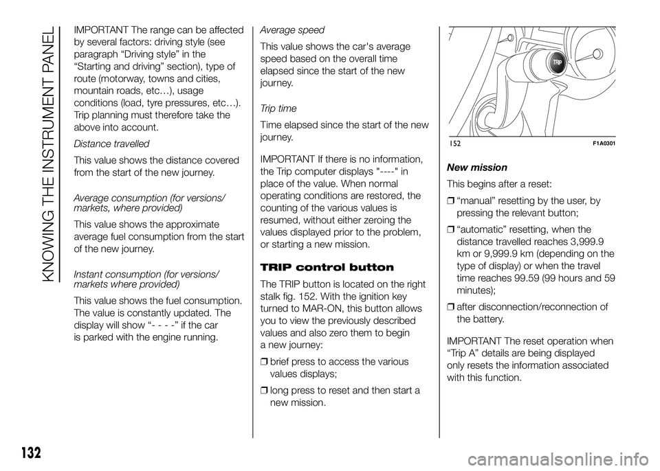
TRIP control button
The TRIP button is located on the right
stalk fig. 152. With the ignition key
turned to MAR-ON, this button allows
you to view the previously described
values and also zero them to begin
a new journey:
❒brief press to access the various
values displays;
❒long press to reset and then start a
new mission.New mission
This begins after a reset:
❒“manual” resetting by the user, by
pressing the relevant button;
❒“automatic” resetting, when the
distance travelled reaches 3,999.9
km or 9,999.9 km (depending on the
type of display) or when the travel
time reaches 99.59 (99 hours and 59
minutes);
❒after disconnection/reconnection of
the battery.
IMPORTANT The reset operation when
“Trip A” details are being displayed
only resets the information associated
with this function.
TRIP
152F1A0301
132
KNOWING THE INSTRUMENT PANEL
Page 385 of 387
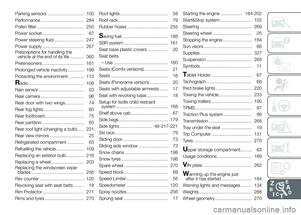
Parking sensors ............................. 100
Performance .................................. 284
Pollen filter ..................................... 250
Power socket ................................. 67
Power steering fluid........................ 247
Power supply ................................. 267
Prescriptions for handling the
vehicle at the end of its life ........... 360
Pretensioners ................................. 161
Prolonged vehicle inactivity............. 199
Protecting the environment ............ 113
Radio ............................................ 106
Rain sensor .................................... 53
Rear camera .................................. 96
Rear door with two wings............... 74
Rear fog lights ................................ 60
Rear footboard ............................... 75
Rear partition ................................. 65
Rear roof light (changing a bulb) ..... 221
Rear view mirrors ........................... 25
Refrigerated compartment ............. 63
Refuelling the vehicle ...................... 109
Replacing an exterior bulb .............. 216
Replacing a wheel .......................... 203
Replacing the windscreen wiper
blades .......................................... 256
Rev counter ................................... 120
Revolving seat with seat belts ........ 18
Rim Protector................................. 271
Rims and tyres ............................... 270Roof lights...................................... 58
Roof rack ....................................... 79
Rubber hoses ................................ 255
Saving fuel .................................... 188
SBR system ................................... 161
Seat base plastic covers ................ 20
Seat belts
– Use ........................................... 160
Seats (Combi versions)................... 21
Seats ............................................. 16
Seats (Panorama version)............... 20
Seats with adjustable armrests....... 17
Seat with revolving base................. 18
Setup for Isofix child restraint
system ......................................... 168
Shelf above cab ............................. 67
Side bags....................................... 179
Side lights ......................... 48-217-221
Ski rack.......................................... 79
Sliding door.................................... 73
Sliding side window ....................... 73
Snow chains .................................. 198
Snow tyres ..................................... 198
Spare wheel ................................... 270
Speed block................................... 69
Speed Limiter................................. 56
Speedometer ................................. 120
Spray nozzles................................. 256
Sprung seat ................................... 17Starting the engine ................. 184-202
Start&Stop system ......................... 102
Steering ......................................... 269
Steering wheel ............................... 25
Stopping the engine ....................... 184
Sun visors ...................................... 66
Supplies ......................................... 327
Suspension .................................... 268
Symbols......................................... 11
Tablet Holder ................................ 67
Tachograph .................................... 68
third brake lights ............................ 220
Towing the vehicle .......................... 233
Towing trailers ................................ 190
TPMS............................................. 87
Traction Plus system ...................... 86
Transmission .................................. 268
Tray under the seat ........................ 19
Trip Computer ................................ 131
Tyres .............................................. 270
Upper storage compartment......... 63
Usage conditions ........................... 189
VIN plate ....................................... 262
Warming up the engine just
after it has started ........................ 184
Warning lights and messages......... 134
Weights.......................................... 286
Wheel geometry ............................. 270