FIAT DUCATO BASE CAMPER 2017 Owner handbook (in English)
DUCATO BASE CAMPER 2017
FIAT
FIAT
https://www.carmanualsonline.info/img/10/32570/w960_32570-0.png
FIAT DUCATO BASE CAMPER 2017 Owner handbook (in English)
Trending: compression ratio, airbag disable, fuel consumption, differential, air filter, jump cable, Change miles to km
Page 151 of 296
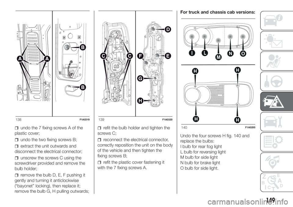
undo the 7 fixing screws A of the
plastic cover;
undo the two fixing screws B;
extract the unit outwards and
disconnect the electrical connector;
unscrew the screws C using the
screwdriver provided and remove the
bulb holder;
remove the bulb D, E, F pushing it
gently and turning it anticlockwise
(“bayonet” locking), then replace it;
remove the bulb G, H pulling outwards;
refit the bulb holder and tighten the
screws C;
reconnect the electrical connector,
correctly reposition the unit on the body
of the vehicle and then tighten the
fixing screws B;
refit the plastic cover fastening it
with the 7 fixing screws A.For truck and chassis cab versions:
Undo the four screws H fig. 140 and
replace the bulbs:
I bulb for rear fog light
L bulb for reversing light
M bulb for side light
N bulb for brake light
O bulb for side light.
138F1A0319139F1A0320
140F1A0200
149
Page 152 of 296
THIRD BRAKE LIGHTS
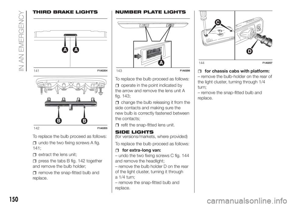
To replace the bulb proceed as follows:
undo the two fixing screws A fig.
141;
extract the lens unit;
press the tabs B fig. 142 together
and remove the bulb holder;
remove the snap-fitted bulb and
replace.NUMBER PLATE LIGHTS
To replace the bulb proceed as follows:
operate in the point indicated by
the arrow and remove the lens unit A
fig. 143;
change the bulb releasing it from the
side contacts and making sure the
new bulb is correctly fastened between
the contacts;
refit the snap-fitted lens unit.
SIDE LIGHTS
(for versions/markets, where provided)
To replace the bulb proceed as follows:
for extra-long van:
– undo the two fixing screws C fig. 144
and remove the headlight;
– remove the bulb holder D on the rear
of the light cluster, turning it through
a 1/4 turn;
– remove the snap-fitted bulb and
replace.
for chassis cabs with platform:
– remove the bulb-holder on the rear of
the light cluster, turning through 1/4
turn;
– remove the snap-fitted bulb and
replace.141F1A0204
142F1A0205
143F1A0206
144F1A0207
150
IN AN EMERGENCY
Page 153 of 296
REPLACING
INTERIOR BULBS
For the type of bulb and relevant power
rating, see “Changing a bulb”.
FRONT CEILING LIGHT
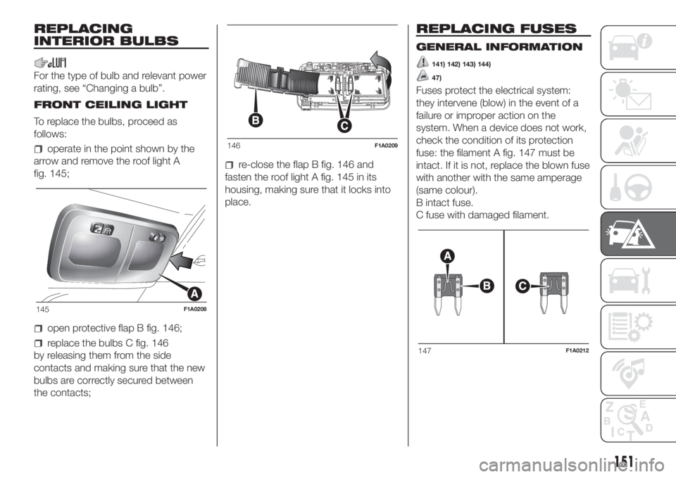
To replace the bulbs, proceed as
follows:
operate in the point shown by the
arrow and remove the roof light A
fig. 145;
open protective flap B fig. 146;
replace the bulbs C fig. 146
by releasing them from the side
contacts and making sure that the new
bulbs are correctly secured between
the contacts;
re-close the flap B fig. 146 and
fasten the roof light A fig. 145 in its
housing, making sure that it locks into
place.
REPLACING FUSES
GENERAL INFORMATION
141) 142) 143) 144)
47)
Fuses protect the electrical system:
they intervene (blow) in the event of a
failure or improper action on the
system. When a device does not work,
check the condition of its protection
fuse: the filament A fig. 147 must be
intact. If it is not, replace the blown fuse
with another with the same amperage
(same colour).
B intact fuse.
C fuse with damaged filament.
145F1A0208
146F1A0209
147F1A0212
151
Page 154 of 296
FUSE LOCATION
The vehicle fuses are grouped in three
control units located on the dashboard,
passenger compartment right pillar
and engine compartment.
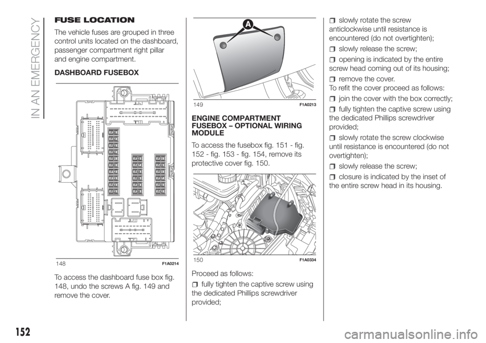
DASHBOARD FUSEBOX
To access the dashboard fuse box fig.
148, undo the screws A fig. 149 and
remove the cover.ENGINE COMPARTMENT
FUSEBOX – OPTIONAL WIRING
MODULE
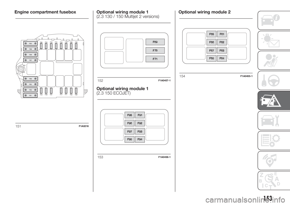
To access the fusebox fig. 151 - fig.
152 - fig. 153 - fig. 154, remove its
protective cover fig. 150.
Proceed as follows:
fully tighten the captive screw using
the dedicated Phillips screwdriver
provided;
slowly rotate the screw
anticlockwise until resistance is
encountered (do not overtighten);
slowly release the screw;
opening is indicated by the entire
screw head coming out of its housing;
remove the cover.
To refit the cover proceed as follows:
join the cover with the box correctly;
fully tighten the captive screw using
the dedicated Phillips screwdriver
provided;
slowly rotate the screw clockwise
until resistance is encountered (do not
overtighten);
slowly release the screw;
closure is indicated by the inset of
the entire screw head in its housing.
148F1A0214
149F1A0213
150F1A0334
152
IN AN EMERGENCY
Page 155 of 296
Engine compartment fusebox Optional wiring module 1
(2.3 130 / 150 Multijet 2 versions)
Optional wiring module 1
(2.3 150 ECOJET)Optional wiring module 2
151F1A0216
152F1A0457-1
153F1A0458-1
154F1A0455-1
153
Page 156 of 296
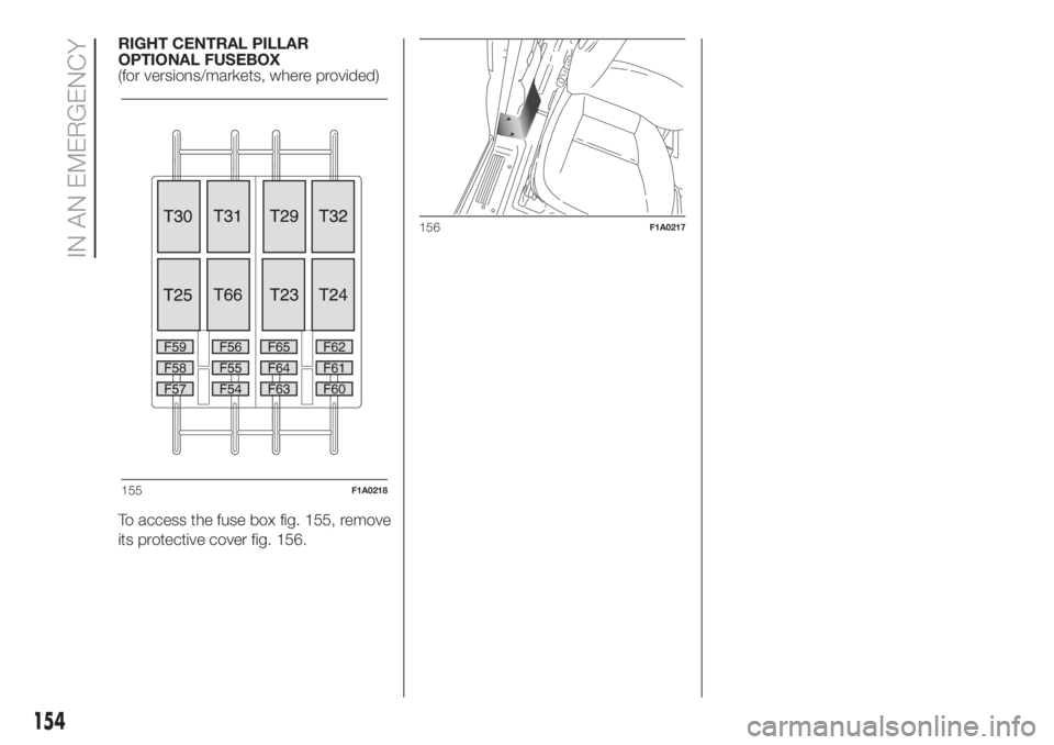
RIGHT CENTRAL PILLAR
OPTIONAL FUSEBOX
(for versions/markets, where provided)
To access the fuse box fig. 155, remove
its protective cover fig. 156.
155F1A0218
156F1A0217
154
IN AN EMERGENCY
Page 157 of 296
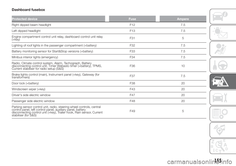
Dashboard fusebox
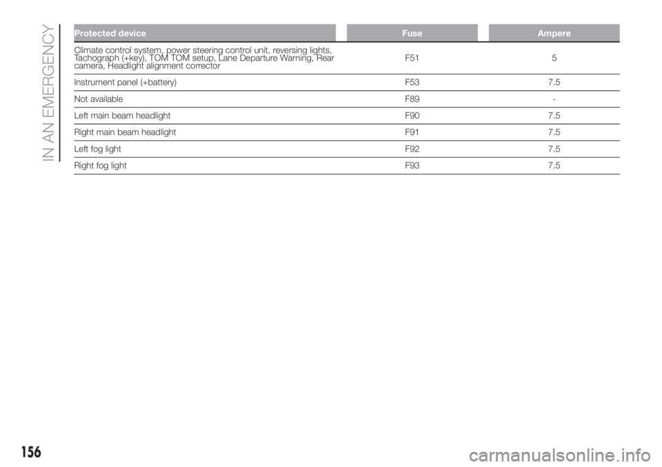
Protected device Fuse Ampere
Right dipped beam headlight F12 7.5
Left dipped headlight F13 7.5
Engine compartment control unit relay, dashboard control unit relay
(+key)F31 5
Lighting of roof lights in the passenger compartment (+battery) F32 7.5
Battery monitoring sensor for Start&Stop versions (+battery) F33 7.5
Minibus interior lights (emergency) F34 7.5
Radio, Climate control system, Alarm, Tachograph, Battery
disconnecting control unit, Timer Webasto timer (+battery), TPMS,
Current stabiliser for radio setup (S&S)F36 10
Brake lights control (main), Instrument panel (+key), Gateway (for
transformers)F37 7.5
Door lock (+battery) F38 20
Windscreen wiper (+key) F43 20
Driver's side electric window F47 20
Passenger side electric window F48 20
Parking sensor control unit, radio, steering wheel controls, central
control panel, left control panel, auxiliary panel, battery
disconnecting control unit (+key), Trailer hook, Rain sensor, Current
stabiliser (for S&S)F49 5
155
Page 158 of 296
Protected device Fuse Ampere
Climate control system, power steering control unit, reversing lights,
Tachograph (+key), TOM TOM setup, Lane Departure Warning, Rear
camera, Headlight alignment correctorF51 5
Instrument panel (+battery) F53 7.5
Not available F89 -
Left main beam headlight F90 7.5
Right main beam headlight F91 7.5
Left fog light F92 7.5
Right fog light F93 7.5
156
IN AN EMERGENCY
Page 159 of 296
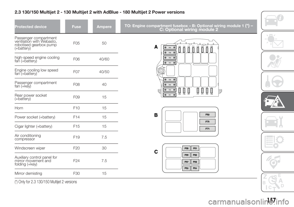
2.3 130/150 Multijet 2 - 130 Multijet 2 with AdBlue - 180 Multijet 2 Power versions
Protected device Fuse AmpereTO: Engine compartment fusebox – B: Optional wiring module 1(*) –
C: Optional wiring module 2
Passenger compartment
ventilation with Webasto,
robotised gearbox pump
(+battery)F05 50
high-speed engine cooling
fan (+battery)F06 40/60
Engine cooling low speed
fan (+battery)F07 40/50
Passenger compartment
fan (+key)F08 40
Rear power socket
(+battery)F09 15
Horn F10 15
Power socket (+battery) F14 15
Cigar lighter (+battery) F15 15
Air conditioning
compressorF19 7.5
Windscreen wiper F20 30
Auxiliary control panel for
mirror movement and
folding (+key)F24 7.5
Mirror demisting F30 15
(*) Only for 2.3 130/150 Multijet 2 versions
157
Page 160 of 296
Protected device Fuse AmpereTO: Engine compartment fusebox – B: Optional wiring module 1(*) –
C: Optional wiring module 2
Webasto control unit F61 30
Passenger compartment
fan with WebastoF62 20
Trailer hook socket F63 20
Headlight washers F64 30
Trailer control unit F65 15
Trailer control unit F66 15
Trailer hook socket F67 20
(*) Only for 2.3 130/150 Multijet 2 versions
158
IN AN EMERGENCY
Trending: battery capacity, clock setting, remove seats, headlamp, fuel cap, maintenance schedule, refuelling
