FIAT DUCATO BASE CAMPER 2017 Owner handbook (in English)
Manufacturer: FIAT, Model Year: 2017, Model line: DUCATO BASE CAMPER, Model: FIAT DUCATO BASE CAMPER 2017Pages: 296, PDF Size: 14.44 MB
Page 141 of 296
 INSTRUCTIONS FOR
USING THE REMOVABLE
BALL HEAD TOW BAR
40) 41) 42) 43) 44) 45)Before setting off, check the correct
locking of the removable ball head tow
bar, as follows:
The green mark of the flywhe")
INSTRUCTIONS FOR
USING THE REMOVABLE
BALL HEAD TOW BAR
40) 41) 42) 43) 44) 45)Before setting off, check the correct
locking of the removable ball head tow
bar, as follows:
The green mark of the flywheel must
coincide with the green mark on the
tow bar.
The flywheel is in the stop position
on the tow bar (without slot).
Locked lock and key removed. The
flywheel cannot be removed.
Ball head bar firmly secured to the
housing pipe. Check by shaking with a
hand.
The fitting procedure must be repeated
if any of the 4 checked requirements
is not met.
If even only one of the requirements is
not met the tow hook must not be
used, as in this case there is risk of
accidents. Contact the joint
manufacturer.
The ball head tow bar can be fitted and
removed manually, without needing
any tool.
Never use working tools or means, as
the mechanism could be damaged.
Never unlock in the case of trailer
attached to the vehicle or fitted rack.When driving without trailer or rack the
ball head tow bar must be removed
and the closing plug must always
be inserted in the housing pipe. This
applies particularly if the visibility of the
number plate characters or of the
lighting system is reduced.
Removable ball head tow bar fig.
123 - fig. 124 - fig. 125
1. Mounting pipe - 2. Ball head tow bar
- 3. Locking ball - 4. Release lever -
5. Handwheel - 6. Cap - 7. Wrench - 8.
Red mark (handwheel) - 9. Green
mark (handwheel) - 10. Green mark
(tow bar) - 11. Symbol (release control)
- 12. Closing plug - 13. Coupling pin
- 14. No gaps between 2 and5-15.
Gap of about 5 mm
Installing the ball head tow bar
1. Remove the plug from the mounting
pipe.
The ball head tow bar is usually in the
released position when taken out from
the boot. This can be observed by
the flywheel spaced from the tow bar,
corresponding to a slot of approx. 5
mm (see figure) and by the red mark on
the flywheel directed to the green
mark on the tow bar.
123F1A0380
124 - Locked position, drivingF1A0381
125 - Released position, removedF1A0382
139
Page 142 of 296
 Please note that the tow bar can be
installed only when in these conditions.
If the locking mechanism of the tow
bar is disengaged before the
installation, or at any other time, and is
in the locked p")
Please note that the tow bar can be
installed only when in these conditions.
If the locking mechanism of the tow
bar is disengaged before the
installation, or at any other time, and is
in the locked position, it must be
pre-loaded. The locked position can be
identified by the green mark of the
flywheel coinciding with the green mark
of the tow bar and by the flywheel in
the stop position on the tow bar,
namely without slot (see figure).
The locking mechanism is pre-loaded
as follows: with the key inserted and
the lock open, extract the flywheel
following the direction of the arrow and,
to pre-load, rotate according to the
direction of the arrow b until the stop.
The release lever is engaged and the
locking mechanism remains in the
pre-loading position even when the
flywheel is released. The tow bar must
be inserted in the housing pipe with the
coupling pin for the installation. Insert
from the bottom and push upwards.
The mechanism then locks
automatically. Keep your hands far from
the flywheel, as it rotates during the
locking procedure.2. The tow bar must be inserted in the
housing pipe with the coupling pin
for the installation. Insert from the
bottom and push upwards. The
mechanism then locks automatically.
Keep your hands far from the flywheel,
as it rotates during the locking
procedure.
3. Close the lock and always remove
the key. The key cannot be removed
when the lock is released. Apply the
protection cap on the lock.
Removing the tow bar
1. Remove the protection cap from the
lock and press it on the key grip. Open
the lock with the key.
2. Hold the tow bar firmly, remove the
flywheel following the direction of the
arrow and rotate according to the
direction of the arrow b until stopping,
so as to remove till the extracted
position. Then remove the tow bar from
the housing pipe. The flywheel can
then be released; it autonomously
stops in the released position.
3. Arrange the tow bar in the luggage
compartment so that it cannot be
dirtied or damaged by other
transported objects.
4. Insert the suitable plug in the
mounting pipe.
WARNING
40)The removable ball head bar must be
repaired and taken apart by the
manufacturer only.
41)The accompanying plate must be in a
highly visible point of the vehicle, near
the mounting pipe or inside the luggage
compartment.
42)To ensure correct operation of the
system, periodically remove all dirt deposits
from the ball head bar and from the
mounting pipe. The mechanical
components must be serviced at the
specified intervals. The lock must only be
treated with graphite.
43)Periodically lubricate the joints, the
sliding surfaces and the balls with grease
without resin or oil. Lubrication is also a
further corrosion protection.
44)If the vehicle is washed with high-
pressure jets, the ball head bar must be
removed and the dedicated cap fitted. The
ball head bar must never be treated with
steam jets.
45)Two keys are supplied together with
the removable ball tow bar. Note down the
key number on the pawl for any following
order and keep it.
140
STARTING AND DRIVING
Page 143 of 296
 PROLONGED
VEHICLE INACTIVITY
If the vehicle needs to be off the road
for longer than one month, the following
precautions must be taken:
park the vehicle indoors in a dry
and, if possible, well-ventil")
PROLONGED
VEHICLE INACTIVITY
If the vehicle needs to be off the road
for longer than one month, the following
precautions must be taken:
park the vehicle indoors in a dry
and, if possible, well-ventilated place;
engage a gear;
check that the handbrake is not
engaged;
disconnect the negative battery
terminal; if the vehicle is equipped with
a battery disconnection function
(disconnector), see the description of
the procedure in the "Controls"
paragraph in the "Dashboard and
controls" section;
clean and protect the painted parts
using protective wax;
clean and protect the shiny metal
parts using special compounds
available commercially;
sprinkle talcum powder on the
windscreen and rear window wiper
rubber blades and lift them off the
glass;
slightly open the windows;
cover the vehicle with a piece of
fabric or perforated plastic sheet. Do
not use compact plastic tarpaulins,
which prevent humidity from
evaporating from the surface of the
vehicle;
inflate tyres to +0.5 bar above the
standard specified pressure and check
it at intervals;
do not drain the engine cooling
system.
IMPORTANT If the vehicle is equipped
with an alarm system, switch off the
vehicle alarm with the remote control.
IMPORTANT After turning the ignition
key to STOP and having closed the
driver side door, wait at least one
minute before disconnecting the
electrical supply from the battery. When
reconnecting the electrical supply to
the battery, make sure that the ignition
key is in the STOP position and the
driver side door is closed.
141
Page 144 of 296
 IN AN EMERGENCY
A punctured tyre or a burnt-out bulb?
At times, a problem may interfere
with our journey.
The pages on emergencies can help
you to deal with critical situations
independently and with")
IN AN EMERGENCY
A punctured tyre or a burnt-out bulb?
At times, a problem may interfere
with our journey.
The pages on emergencies can help
you to deal with critical situations
independently and with calm.
In an emergency we recommend that
you call the freephone number found in
the Warranty Booklet.
It is also possible to call the 00 800
3428 0000 freephone number to
search the nearest Fiat Dealership.REPLACING A BULB ......................143
REPLACING AN EXTERIOR BULB ..146
REPLACING INTERIOR BULBS ......151
REPLACING FUSES........................151
GATEWAY FMS MODULE ...............165
CHANGING A WHEEL ....................170
FIX & GO AUTOMATIC QUICK
TYRE REPAIR KIT ...........................174
JUMP STARTING ............................177
RECHARGING THE BATTERY ........178
FUEL CUT-OFF SWITCH ................179
TOWING THE VEHICLE ..................180
142
IN AN EMERGENCY
Page 145 of 296
 REPLACING A BULB
GENERAL
INSTRUCTIONS
139) 140)
46)
When a light is not working, check
that the corresponding fuse is intact
before changing a bulb. For the location
of fuses, refer to the paragraph
&")
REPLACING A BULB
GENERAL
INSTRUCTIONS
139) 140)
46)
When a light is not working, check
that the corresponding fuse is intact
before changing a bulb. For the location
of fuses, refer to the paragraph
"Replacing fuses" in this chapter.
before changing a bulb check the
contacts for oxidation;
burnt bulbs must be replaced by
others of the same type and power;
always check the headlight beam
direction after changing a bulb;
IMPORTANT A slight misting may
appear on the internal surface of the
headlight: this does not indicate a fault
and is caused by low temperature
and the degree of humidity in the air.
Misting will rapidly disappear when the
headlights are switched on. The
presence of drops inside the headlights
indicates infiltration of water. Contact
a Fiat Dealership.
WARNING
139)Modifications or repairs to the
electric system that are not carried out
properly or do not take the system
technical specifications into account can
cause malfunctions leading to the risk
of fire.
140)Halogen bulbs contain pressurised
gas, in the case of breakage they may
burst causing glass fragments to be
projected outwards.
WARNING
46)Halogen bulbs must be handled
holding the metallic part only. Touching the
transparent part of the bulb with your
fingers may reduce the intensity of the
emitted light and even reduce the lifespan
of the bulb. In the event of accidental
contact, wipe the bulb with a cloth
moistened with alcohol and let the bulb
dry.
143
Page 146 of 296
 BULB TYPES
Various types of bulbs are fitted to your vehicle.
All-glass bulb:(type A) these are pressure fitted - pull to remove.
Bayonet bulb:(type B) to remove them press the bulb and turn it
anticl")
BULB TYPES
Various types of bulbs are fitted to your vehicle.
All-glass bulb:(type A) these are pressure fitted - pull to remove.
Bayonet bulb:(type B) to remove them press the bulb and turn it
anticlockwise.
Cylindrical bulbs:(type C) release them from their contacts to remove.
Halogen bulbs:(type D) to remove the bulb, release it and extract it
from its seat.
Halogen bulbs:(type E) to remove the bulb, release it and extract it
from its seat.
144
IN AN EMERGENCY
Page 147 of 296
 Light bulbs
 Type Power Figure ref.
Main beam headlights H7 55W D
Dipped beam headlights H7 55W D
Front side lights / daytime running lights
W21/5W - LED
(#)--
Front fog lights
(*)H11 55W -")
Light bulbs
Light bulbs Type Power Figure ref.
Main beam headlights H7 55W D
Dipped beam headlights H7 55W D
Front side lights / daytime running lights
W21/5W - LED
(#)--
Front fog lights
(*)H11 55W -
Front direction indicators WY21W 21W B
Side turn lightW16WF
(**) / WY5W
(***)16W(**) / 5W (***)A
Rear direction indicators PY2IW 21W B
Side lights W5W 5W A
Rear side lights P21/5W 21/5W B
Rear side lights/Brake lights P21W 21W B
Third brake light W5W 5W B
Reverse gear W16W 16W B
Rear fog light W16W 16W B
Number plate C5W 5W A
Front roof light (movable lens) 12V10W 10W C
Rear ceiling light 12V10W 10W C
(#) where provided, instead of bulb W21/5W
(*)for versions/markets, where provided
(**)XL and Tempo Libero versions
(***)all other versions
145
Page 148 of 296
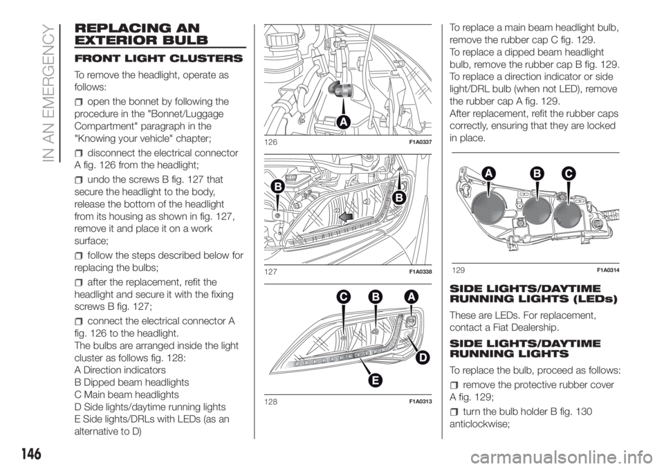
REPLACING AN
EXTERIOR BULB
FRONT LIGHT CLUSTERS
To remove the headlight, operate as
follows:
open the bonnet by following the
procedure in the "Bonnet/Luggage
Compartment" paragraph in the
"Knowing your vehicle" chapter;
disconnect the electrical connector
A fig. 126 from the headlight;
undo the screws B fig. 127 that
secure the headlight to the body,
release the bottom of the headlight
from its housing as shown in fig. 127,
remove it and place it on a work
surface;
follow the steps described below for
replacing the bulbs;
after the replacement, refit the
headlight and secure it with the fixing
screws B fig. 127;
connect the electrical connector A
fig. 126 to the headlight.
The bulbs are arranged inside the light
cluster as follows fig. 128:
A Direction indicators
B Dipped beam headlights
C Main beam headlights
D Side lights/daytime running lights
E Side lights/DRLs with LEDs (as an
alternative to D)To replace a main beam headlight bulb,
remove the rubber cap C fig. 129.
To replace a dipped beam headlight
bulb, remove the rubber cap B fig. 129.
To replace a direction indicator or side
light/DRL bulb (when not LED), remove
the rubber cap A fig. 129.
After replacement, refit the rubber caps
correctly, ensuring that they are locked
in place.
SIDE LIGHTS/DAYTIME
RUNNING LIGHTS (LEDs)
These are LEDs. For replacement,
contact a Fiat Dealership.
SIDE LIGHTS/DAYTIME
RUNNING LIGHTS
To replace the bulb, proceed as follows:
remove the protective rubber cover
A fig. 129;
turn the bulb holder B fig. 130
anticlockwise;
126F1A0337
127F1A0338
128F1A0313
129F1A0314
146
IN AN EMERGENCY
Page 149 of 296
 extract the bulb by pulling and
replace it;
remove the bulb by pushing it
slightly and turning it anticlockwise
(bayonet mount);
refit the bulb holder B by turning it
clockwise and making sure that it")
extract the bulb by pulling and
replace it;
remove the bulb by pushing it
slightly and turning it anticlockwise
(bayonet mount);
refit the bulb holder B by turning it
clockwise and making sure that it locks
correctly
refit the protective rubber cover A
fig. 129.
MAIN BEAM HEADLIGHTSTo replace the bulb, proceed as follows:
remove the protective rubber cover
C fig. 129;
free the bulb holder A fig. 131 from
the side clips B and remove it;
disconnect the electrical connector;
fit the new bulb, ensuring that the
outline of the metal part coincides with
the grooves on the curve of the
headlight, pressing to engage it with the
side clips;
reconnect the electrical connector;
refit the protective rubber cover
C fig. 129.
DIPPED BEAM
HEADLIGHTS
With incandescent bulbs
To replace the bulb, proceed as follows:
remove the protective rubber cover
B fig. 129;
free the bulb holder A fig. 132 from
the side clips B and remove it;
disconnect the electrical connector;
fit the new bulb, ensuring that the
outline of the metal part coincides with
the grooves on the curve of the
headlight, pressing to engage it with the
side clips;
reconnect the electrical connector;
refit the protective rubber cover
B fig. 129.
DIRECTION INDICATORS
To replace the bulb, proceed as follows:
remove the protective rubber cover
A fig. 129;
turn the bulb holder B fig. 133
anticlockwise;
extract the bulb by pulling and
replace it;
remove the bulb by pushing it
slightly and turning it anticlockwise
(bayonet mount);
refit the bulb holder B by turning it
clockwise and making sure that it locks
correctly
refit the protective rubber cover A
fig. 129.
130F1A0386
131F1A0315
132F1A0316
147
Page 150 of 296
 Side
To change the bulbs, proceed as
follows fig. 134:
move the mirror manually to permit
access to the two fixing screws A;
using the Phillips screwdriver
provided, undo the screws and extract
the bu")
Side
To change the bulbs, proceed as
follows fig. 134:
move the mirror manually to permit
access to the two fixing screws A;
using the Phillips screwdriver
provided, undo the screws and extract
the bulb holder assembly, releasing it
from the teeth;
undo the bulb and replace bulb B,
turning it anticlockwise.FOG LIGHTS
(for versions/markets, where provided)
To replace the front fog light bulbs,
proceed as follows:
steer the wheel completely inwards;
undo the screw A and remove the
flap B fig. 135;
release the clip C fig. 136 and
disconnect the electrical connector D;
turn and remove the bulb holder E;
release the bulb and replace it;
refit the new bulb and carry out the
procedure described previously in
reverse.REAR LIGHT CLUSTERS
The bulbs are arranged inside the light
cluster as follows fig. 137:
A brake/side lights
B side light
C direction indicators
D reverse lights.
E rear fog lights
To replace the bulb, proceed as follows
fig. 138, fig. 139:
open the rear wing door.
133F1A0317
134F1A0195
135F1A0361
136F1A0362
137F1A0318
148
IN AN EMERGENCY