ESP FIAT DUCATO BASE CAMPER 2017 Owner handbook (in English)
[x] Cancel search | Manufacturer: FIAT, Model Year: 2017, Model line: DUCATO BASE CAMPER, Model: FIAT DUCATO BASE CAMPER 2017Pages: 296, PDF Size: 14.44 MB
Page 93 of 296
WARNING
77)If the camera loses its position due to
a load variation, the system may not work
temporarily to allow the camera to perform
an auto-calibration.
78)The Driving Advisor is not an automatic
driving system and does not replace the
driver in controlling the trajectory of the
vehicle. The driver is personally responsible
for maintaining sufficient attention for the
traffic and road conditions and for
controlling the vehicle's trajectory safely.
79)In the case of indistinct, overlapping or
missing lane demarcation lines, the system
may not assist the driver: in this case the
Driving Advisor will be inactive.
91
Page 95 of 296
SEAT BELTS
IN BRIEF
All the seats in the vehicle are
equipped with seat belts with three
anchoring points and a retractor. The
reel mechanism operates locking
the belt in the event of sharp braking
or strong deceleration due to an
impact. This allows the belt strap to
slide freely and to adapt to the body
of the occupant. In the event of an
accident, the belt will lock to reduce
the risk of impact inside the
passenger compartment or of being
projected outside the vehicle. The
driver is responsible for respecting,
and ensuring that all the other
occupants of the vehicle also
respect, the local laws in force in
relation to the use of the seat belts.
Always fasten the seat belts before
setting off.
USING THE SEAT BELTS
The belt should be worn keeping the
torso straight and rested against the
backrest.
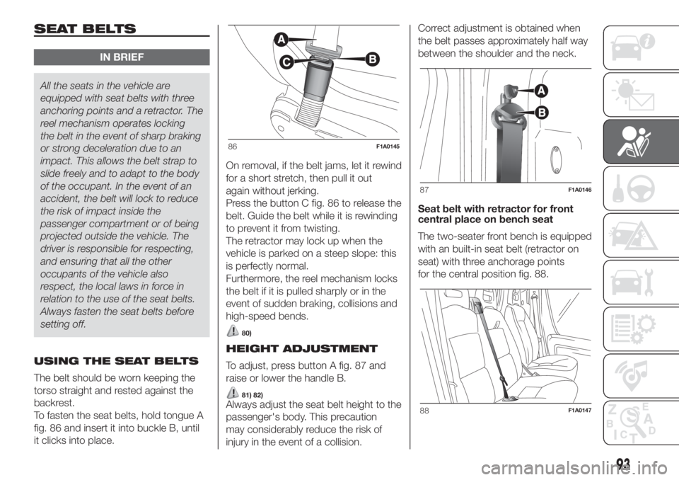
To fasten the seat belts, hold tongue A
fig. 86 and insert it into buckle B, until
it clicks into place.On removal, if the belt jams, let it rewind
for a short stretch, then pull it out
again without jerking.
Press the button C fig. 86 to release the
belt. Guide the belt while it is rewinding
to prevent it from twisting.
The retractor may lock up when the
vehicle is parked on a steep slope: this
is perfectly normal.
Furthermore, the reel mechanism locks
the belt if it is pulled sharply or in the
event of sudden braking, collisions and
high-speed bends.
80)
HEIGHT ADJUSTMENT
To adjust, press button A fig. 87 and
raise or lower the handle B.
81) 82)Always adjust the seat belt height to the
passenger's body. This precaution
may considerably reduce the risk of
injury in the event of a collision.Correct adjustment is obtained when
the belt passes approximately half way
between the shoulder and the neck.
Seat belt with retractor for front
central place on bench seat
The two-seater front bench is equipped
with an built-in seat belt (retractor on
seat) with three anchorage points
for the central position fig. 88.
86F1A0145
87F1A0146
88F1A0147
93
Page 100 of 296
GROUP 1
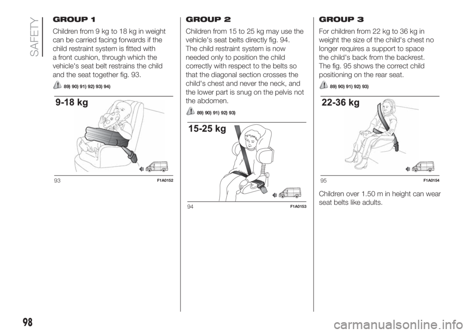
Children from 9 kg to 18 kg in weight
can be carried facing forwards if the
child restraint system is fitted with
a front cushion, through which the
vehicle's seat belt restrains the child
and the seat together fig. 93.
89) 90) 91) 92) 93) 94)
GROUP 2
Children from 15 to 25 kg may use the
vehicle's seat belts directly fig. 94.
The child restraint system is now
needed only to position the child
correctly with respect to the belts so
that the diagonal section crosses the
child's chest and never the neck, and
the lower part is snug on the pelvis not
the abdomen.
89) 90) 91) 92) 93)
GROUP 3
For children from 22 kg to 36 kg in
weight the size of the child's chest no
longer requires a support to space
the child's back from the backrest.
The fig. 95 shows the correct child
positioning on the rear seat.
89) 90) 91) 92) 93)
Children over 1.50 m in height can wear
seat belts like adults.
93F1A0152
94F1A0153
95F1A0154
98
SAFETY
Page 102 of 296
Below is a summary of
the main safety rules to
be followed when
carrying children
The recommended position for
installing child restraint systems is on
the rear seat, as it is the most protected
area in the event of an impact.
Keep children in rearward-facing
child restraint systems for as long
as possible, ideally until they are 3–4
years old.
If the passenger front airbag is
deactivated, always check the
corresponding LED on the button
on
the instrument panel to make sure
that it has actually been deactivated.
Carefully follow the instructions that
come with the child seat, which the
manufacturer must supply. Keep the
instructions in the vehicle along with the
other papers and this handbook. Do
not use second-hand child seats
without instructions.
Always check that the seat belt is
well fastened by pulling on it.
Only one child is to be strapped into
each restraint system; never carry two
children using one child restraint
system.
Always check that seat belts do not
rest on the child’s neck.
While travelling, do not let the child
sit incorrectly or unfasten the belts.
Never carry children on your lap,
even newborns. No one can hold
a child in the case of an accident.
Never allow a child to put the belt's
diagonal section under an arm or
behind their back.
If the vehicle has been involved in a
road accident, replace the child
restraint system with a new one. In
addition, and depending on the type of
child restraint system installed, replace
the Isofix anchorages or the seat belt
with which the child restraint system
was connected.
The rear headrest can be removed if
needed to install a child restraint
system. The headrest must always be
fitted in the vehicle if the seat is used by
an adult passenger or a child sitting in
a restraint system without backrest.
WARNING
87)Do not place a rearward facing cradle
seat on the front seat if the passenger side
airbag is enabled. Deployment of the
airbag in an accident could cause fatal
injuries to the child regardless of the
severity of the impact. It is advisable to
always carry children in a child restraint
system on the rear seat, which is the most
protected position in the event of a
collision. If you need to carry a child on the
front passenger seat in a rearward facing
cradle seat, the passenger side airbags
(front and side bags for chest/pelvis
protection, for versions/markets, where
provided) must be deactivated using
the setup menu. It is important to check
the dedicated LED on button
on the
instrument panel to make sure that they
are actually deactivated. Move the
passenger's seat as far back as possible
to avoid contact between the child seat
and the dashboard.
88)On the sun visor there is a label with
suitable symbols reminding the user that it
is compulsory to deactivate the airbag if
a rearward facing child restraint system is
fitted. Always comply with the instructions
on the passenger side sun visor (see the
"Supplementary Restraint System (SRS)
- Airbag" paragraph).
89)Do not move the front or rear seat if a
child is seated on it or on the dedicated
child restraint system.
100
SAFETY
Page 110 of 296
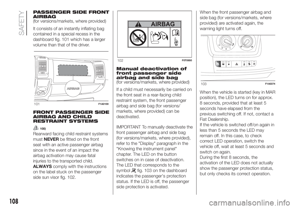
PASSENGER SIDE FRONT
AIRBAG
(for versions/markets, where provided)
It consists of an instantly inflating bag
contained in a special recess in the
dashboard fig. 101 which has a larger
volume than that of the driver.
FRONT PASSENGER SIDE
AIRBAG AND CHILD
RESTRAINT SYSTEMS
100)
Rearward facing child restraint systems
mustNEVERbe fitted on the front
seat with an active passenger airbag
since in the event of an impact the
airbag activation may cause fatal
injuries to the transported child.
ALWAYScomply with the instructions
on the label stuck on the passenger
side sun visor fig. 102.Manual deactivation of
front passenger side
airbag and side bag
(for versions/markets, where provided)
If a child must necessarily be carried on
the front seat in a rear-facing child
restraint system, the front passenger
airbag and side bag (for versions/
markets, where provided) can be
deactivated.
IMPORTANT To manually deactivate the
front passenger airbag and side bag
(for versions/markets, where provided),
refer to the "Display" paragraph in the
"Knowing the instrument panel"
chapter. The LED on the button
switches on in case of deactivation.
The LED that corresponds to the
symbol
fig. 103 on the dashboard
indicates the passenger's protection
status. If the LED is off, the passenger
side protection is activated.When the front passenger airbag and
side bag (for versions/markets, where
provided) are activated again, the
warning light turns off.
When the vehicle is started (key in MAR
position), the LED turns on for approx.
8 seconds, provided that at least 5
seconds have elapsed from the
previous switching off. If not, contact a
Fiat Dealership.
If the vehicle is switched off/on again in
less than 5 seconds the LED may
remain off. In this case, to check
correct LED operation, switch the
vehicle off, wait at least 5 seconds and
switch on again.
During the first 8 seconds, the
activation of the LED does not actually
show the passenger protection status,
but only checks its correct operation.
101F1A0159
102F0T0950
103F1A0374
108
SAFETY
Page 118 of 296
16)If the engine fails to start with a gear
engaged, the potentially dangerous
situation due to the fact that the
transmission is automatically placed in
neutral will be signalled by a buzzer.
17)If the warning light
flashes for 60
seconds after starting or during an
extended towing period, this indicates a
problem in the glow plug preheating
system. Use the vehicle normally if the
engine starts, but contact a Fiat Dealership
as soon as possible.
18)Remember that the brake servo and
power steering are not operational until the
engine has been started, so you need to
apply much more force than usual to
the brake pedal and steering wheel.
19)Never bump start the engine by
pushing, towing or coasting downhill. This
could cause fuel to flow into the catalytic
converter and damage it beyond repair.
20)A quick burst on the accelerator before
stopping the engine serves no practical
purpose; it wastes fuel and is especially
damaging to turbocharged engines.
21)In some cases, when the engine
switches off, the fan could activate for max.
120 seconds.
WHEN PARKED
116)
22)
Proceed as follows when parking and
leaving the vehicle:
engage the gear (on a slope, engage
first gear if the vehicle is facing uphill
or reverse if it is facing downhill) and
leave the wheels steered;
stop the engine and engage the
handbrake;
always remove the ignition key.
If the vehicle is parked on a steep
slope, it is advisable to block the
wheels with a wedge or stone.
On versions equipped with automatic
transmission (Comfort matic), wait
for the letterPto appear on the display
before releasing the brake pedal.
IMPORTANTNEVERleave the vehicle
with the gearbox in neutral (or, on
versions equipped with automatic
(Comfort matic) transmission, before
putting the shift lever in thePposition).HANDBRAKE
Handbrake engagement:The
handbrake lever is located to the left of
the driver's seat. Pull the lever upwards
to engage the handbrake and ensure
that the vehicle does not move.
Handbrake disengagement:slightly
raise the lever, hold the button A
pressed and check that the
warning light switches off on the
instrument panel.
Press the brake pedal when carrying
out this operation to prevent the vehicle
from moving accidentally.
WARNING
116)Never leave children unattended in
the vehicle. Always remove the ignition key
when leaving the vehicle and take it out
with you.
WARNING
22)If the vehicle is equipped with
self-levelling air suspension, always check
that there is sufficient space above the roof
and around the vehicle when parking.
Indeed, the vehicle could raise (or lower)
automatically depending on load or
temperature changes.
116
STARTING AND DRIVING
Page 119 of 296
MANUAL
TRANSMISSION
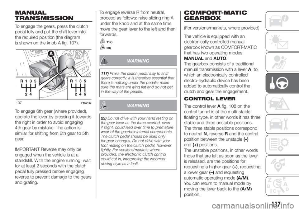
To engage the gears, press the clutch
pedal fully and put the shift lever into
the required position (the diagram
is shown on the knob A fig. 107).
To engage 6th gear (where provided),
operate the lever by pressing it towards
the right in order to avoid engaging
4th gear by mistake. The action is
similar for shifting from 6th gear to 5th
gear.
IMPORTANT Reverse may only be
engaged when the vehicle is at a
standstill. With the engine running, wait
for at least 2 seconds with the clutch
pedal fully pressed before engaging
reverse to prevent damage to the gears
and grating.To engage reverse R from neutral,
proceed as follows: raise sliding ring A
under the knob and at the same time
move the gear lever to the left and then
forwards.
117)
23)
WARNING
117)Press the clutch pedal fully to shift
gears correctly. It is therefore essential that
there is nothing under the pedals: make
sure the mats are lying flat and do not get
in the way of the pedals.
WARNING
23)Do not drive with your hand resting on
the gear lever as the force exerted, even
if slight, could lead over time to premature
wear of the gearbox internal components.
The clutch pedal should be used only
for gear changes. Do not drive with your
foot resting on the clutch pedal, however
lightly. For versions/markets where
provided, the electronic clutch control
could cut in, interpreting the incorrect
driving style as a fault.
COMFORT-MATIC
GEARBOX
(For versions/markets, where provided)
The vehicle is equipped with an
electronically controlled manual
gearbox known as COMFORT-MATIC
that has two operating modes:
MANUALandAUTO.
The gearbox consists of a traditional
manual transmission with a leverA,to
which an electronically controlled
electro-hydraulic device has been
added to automatically control the
clutch and gear the engagement.
CONTROL LEVER
The control leverAfig. 108 on the
central tunnel is of the multi-stable
floating type, in other words it has three
stable and three unstable positions.
The three stable positions correspond
to neutralN, reverseRand the central
position between the unstable(–)
and(+)positions.
The unstable positions, in other words
those that are left as soon as the lever
is released, are the positions for
requesting a higher gear(+), requesting
a lower gear(–)and requesting
automatic operating mode(A/M).
You can return to manual mode by
moving the lever back to the(A/M)
position.
107F1A0163
117
Page 122 of 296
When the device is turned on, the
warning light turns on together with
the corresponding message on the
instrument panel.
Storing vehicle speed
Proceed as follows:
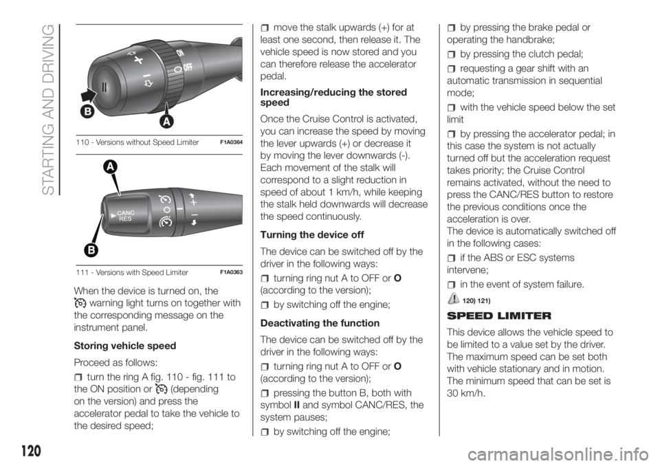
turn the ring A fig. 110 - fig. 111 to
the ON position or
(depending
on the version) and press the
accelerator pedal to take the vehicle to
the desired speed;
move the stalk upwards (+) for at
least one second, then release it. The
vehicle speed is now stored and you
can therefore release the accelerator
pedal.
Increasing/reducing the stored
speed
Once the Cruise Control is activated,
you can increase the speed by moving
the lever upwards (+) or decrease it
by moving the lever downwards (-).
Each movement of the stalk will
correspond to a slight reduction in
speed of about 1 km/h, while keeping
the stalk held downwards will decrease
the speed continuously.
Turning the device off
The device can be switched off by the
driver in the following ways:
turning ring nut A to OFF orO
(according to the version);
by switching off the engine;
Deactivating the function
The device can be switched off by the
driver in the following ways:
turning ring nut A to OFF orO
(according to the version);
pressing the button B, both with
symbolIIand symbol CANC/RES, the
system pauses;
by switching off the engine;
by pressing the brake pedal or
operating the handbrake;
by pressing the clutch pedal;
requesting a gear shift with an
automatic transmission in sequential
mode;
with the vehicle speed below the set
limit
by pressing the accelerator pedal; in
this case the system is not actually
turned off but the acceleration request
takes priority; the Cruise Control
remains activated, without the need to
press the CANC/RES button to restore
the previous conditions once the
acceleration is over.
The device is automatically switched off
in the following cases:
if the ABS or ESC systems
intervene;
in the event of system failure.
120) 121)
SPEED LIMITER
This device allows the vehicle speed to
be limited to a value set by the driver.
The maximum speed can be set both
with vehicle stationary and in motion.
The minimum speed that can be set is
30 km/h.
110 - Versions without Speed LimiterF1A0364
111 - Versions with Speed LimiterF1A0363
120
STARTING AND DRIVING
Page 125 of 296
Reduced sensor sensitivity and a
reduction in the parking assistance
system performance could be due to
the presence on the surface of the
sensor of: ice, snow, mud, thick paint.
The sensor may detect a non-
existent obstacle (echo noise) due to
mechanical noises, for example when
washing the vehicle, in case of rain,
strong wind, hail.
The warnings sent by the sensor
can also be altered by the presence of
ultrasonic systems (e.g. pneumatic
brakes of trucks or pneumatic drills)
near the car.
The performance of the parking
assistance system may also be affected
by the position of the sensors. For
example by a change in the ride setting
(caused by the wear of the shock
absorbers, suspension), changing the
tyres, overloading the vehicle and
carrying out specific tuning operations
that require the vehicle to be lowered.
Detection of obstacles in the upper
part of the vehicle (particularly in the
case of vans or chassis cabs) may not
be guaranteed because the system
detects obstacles that could strike the
lower part of the vehicle.
WARNING
122)The driver is always responsible for
parking and other dangerous manoeuvres.
While carrying out these manoeuvres,
always make sure that no people
(especially children) or animals are in the
area concerned. The parking sensors
are used to assist the driver, who must
never allow his attention to lapse during
potentially dangerous manoeuvres, even
those executed at low speeds.
WARNING
25)For correct operation of the system,
sensors must always be clean from mud,
dirt, snow or ice. Be careful not to scratch
or damage the sensors while cleaning
them. Avoid using dry, rough or hard
cloths. The sensors must be washed using
clean water, with the addition of vehicle
shampoo if necessary.
REAR CAMERA
(PARKVIEW® REAR
BACK UP CAMERA)
(for versions/markets, where provided)
123)
26)
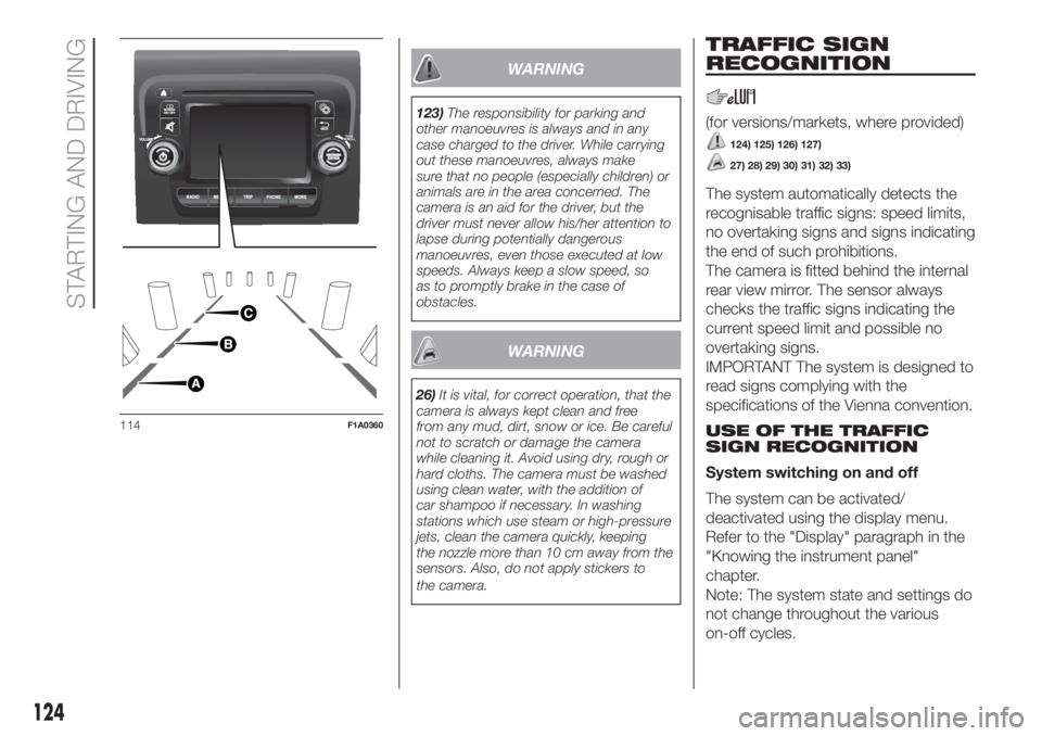
The vehicle may be equipped with a
ParkView® Rear Back Up Camera,
which allows the driver to see the
surrounding area behind the vehicle on
the display when reverse is engaged
or the tailgate is opened fig. 114.
SYMBOLS AND
MESSAGES ON THE
DISPLAY
When displayed, the static line grid
shows the width of the vehicle.
The grid shows separate areas,
allowing you to see the distance from
the rear of the vehicle.
The table below shows the
approximate distances for each area:
Area (reference
fig. 114)Distance from the
rear of the vehicle
Red (A) 0–30 cm
Yellow (B) 30–100 cm
Green (C) 1 m or more
123
Page 126 of 296
WARNING
123)The responsibility for parking and
other manoeuvres is always and in any
case charged to the driver. While carrying
out these manoeuvres, always make
sure that no people (especially children) or
animals are in the area concerned. The
camera is an aid for the driver, but the
driver must never allow his/her attention to
lapse during potentially dangerous
manoeuvres, even those executed at low
speeds. Always keep a slow speed, so
as to promptly brake in the case of
obstacles.
WARNING
26)It is vital, for correct operation, that the
camera is always kept clean and free
from any mud, dirt, snow or ice. Be careful
not to scratch or damage the camera
while cleaning it. Avoid using dry, rough or
hard cloths. The camera must be washed
using clean water, with the addition of
car shampoo if necessary. In washing
stations which use steam or high-pressure
jets, clean the camera quickly, keeping
the nozzle more than 10 cm away from the
sensors. Also, do not apply stickers to
the camera.
TRAFFIC SIGN
RECOGNITION
(for versions/markets, where provided)
124) 125) 126) 127)
27) 28) 29) 30) 31) 32) 33)
The system automatically detects the
recognisable traffic signs: speed limits,
no overtaking signs and signs indicating
the end of such prohibitions.
The camera is fitted behind the internal
rear view mirror. The sensor always
checks the traffic signs indicating the
current speed limit and possible no
overtaking signs.
IMPORTANT The system is designed to
read signs complying with the
specifications of the Vienna convention.
USE OF THE TRAFFIC
SIGN RECOGNITION
System switching on and off
The system can be activated/
deactivated using the display menu.
Refer to the "Display" paragraph in the
"Knowing the instrument panel"
chapter.
Note: The system state and settings do
not change throughout the various
on-off cycles.
114F1A0360
124
STARTING AND DRIVING