ESP FIAT DUCATO BASE CAMPER 2017 Owner handbook (in English)
[x] Cancel search | Manufacturer: FIAT, Model Year: 2017, Model line: DUCATO BASE CAMPER, Model: FIAT DUCATO BASE CAMPER 2017Pages: 296, PDF Size: 14.44 MB
Page 127 of 296
WARNING
124)If the camera loses its position due to
a load variation, the system may not work
temporarily to allow the camera to perform
an auto-calibration.
125)The system only detects the preset
traffic signs. If the minimum visibility
conditions and distance from the sign are
met it can detect all traffic signs.
126)The system is a driving assistance
system but it does not relieve the driver of
the responsibility of driving with due
attention and diligence in compliance with
the laws in force.
127)When the system is active, the driver
is responsible for controlling the vehicle
and monitoring the system, and must
intervene as appropriate if necessary.
WARNING
27)In the event of errors the system may
not work.
28)At low temperatures and in particularly
adverse weather conditions, the system
may not work.
29)Rain, snow, splashes and strong light
contrast may influence the sensor.
30)Do not repair the area of the
windscreen directly surrounding the sensor.
31)If the vehicle is equipped with a
non-genuine suspension kit, the system
may not work correctly.
32)Always use genuine spare parts when
replacing the bulbs of the headlights. Other
bulbs may reduce the system
performance.
33)Clean the windscreen from foreign
matters such as bird droppings, insects,
snow or ice.
REFUELLING THE
VEHICLE
IN BRIEF
Stop the engine before refuelling.
PETROL ENGINES
Only use petrol with an octane number
(RON) no lower than 95 (EN228
specification).
DIESEL ENGINES
Refuel the vehicle exclusively with diesel
for motor vehicles in compliance with
European specification EN590.
OPERATION AT LOW
TEMPERATURES
When using or parking the vehicle for a
long time in the mountains or cold
areas, it is advisable to refuel using
locally available diesel fuel. In this case,
it is also advisable to keep the tank
over 50% full.
34)
100
115F1A0373
125
Page 130 of 296
DO NOT EXCEED THE MAXIMUM
LEVEL. The UREA freezes at under -11
° C. Although the system is designed
to operate below the freezing point
of the UREA, it is advisable not to fill the
tank beyond the maximum level
because if the UREA freezes the
system can be damaged.
If the UREA is spilled on painted
surfaces or aluminium, immediately
clean the area with water and use
absorbent material to collect the fluid
that has been spilled on the ground.
Do not try to start the engine if
UREA was accidentally added to the
Diesel fuel tank, this can result in
serious engine damage, contact
Dealership.
Use AdBlue only according to DIN
70 070 and ISO 22241-1. Other fluids
may cause damage to the system: also
exhaust emissions would no longer
comply with the law. The distribution
companies are responsible for the
compliance of their product. Observe
the precautions of storage and
maintenance, in order to preserve the
initial qualities. The manufacturer of the
vehicle does not recognise any
guarantee in case of malfunctions and
damage caused to the vehicle due
to the use of urea (AdBlue) not in
accordance with regulations.
Any introduction of diesel fuel inside
the tank AdBlue, causes irreversible
damage to the pumping unit circuit
AdBlue.
Do not add additives to AdBlue. Do
not dilute AdBlue with tap water as
this may damage the system of
purification of exhaust gases.
In case of damage to the sewage
system of exhaust gas resulting from
the use of additives / tap water, the
introduction of diesel fuel, or at least by
not fulfilling the requirements, the
warranty expires.
AdBlue tank topping (UREA) in cold
environments
Since AdBlue (UREA) starts to freeze
around the -11 °C, the vehicle is
equipped with an automatic system of
heating UREA that allows the system to
function properly at temperatures
below -11 °C.
If the vehicle remains idle for a long
period at temperatures below the -11
°C, the UREA in the tank might freeze.
If the tank UREA was filled beyond
the maximum level and freezes, it can
be damaged; for this reason it is
advisable not to exceed the maximum
level of the tank.
Pay extra attention to avoid exceeding
the maximum level when you use
portable containers for topping up.Fuel storage - Diesel Fuel
132)
In case of the storage of massive
amounts of fuel, good maintenance is
essential. The fuel contaminated with
water favours the proliferation of
"microbes". These microbes create a
"slime" that can clog the filter system
and fuel pipes. Remove water from the
supply tank and regularly replace the
filter pipe.
NoteWhen a diesel engine runs out of
fuel, air is blown through the fuel
system.
AdBlue storage (UREA)
AdBlue (UREA) is considered a very
stable product with a long shelf life. If is
stored at temperatures between -12
°C and 32 °C, it can be stored at least
for a year.
Since UREA can freeze at temperatures
at or below -11 °C, the system was
designed to operate also in these cold
environments, thanks to an automatic
heating system which operates when
the engine is started.
NoteWhen you need to keep the
AdBlue (UREA), it is important to know
that:
128
STARTING AND DRIVING
Page 135 of 296
LOADING ADVICE
The Fiat Ducato version used by you
has been designed and type approved
on the basis of certain maximum
weights (see "Weights" table in the
"Technical Data" chapter): kerb weight,
payload, total weight, maximum weight
on front axle, maximum weight on
rear axle, towable weight.
IMPORTANT The maximum permitted
load on the floor fastenings is 500
kg; the maximum permitted load on the
side panel is 150 kg.
IMPORTANT For versions with right and
left side flaps, it is advisable to
reposition the release lever in the closed
position before lowering the sides.
133) 134) 135)
39)In addition to these general
precautions, some simple precautions
can improve driving safety, travelling
comfort and vehicle durability:
distribute the load evenly over the
platform: if it is necessary to
concentrate it in a single area, choose
an area mid-way between both axles;
lastly, remember that the vehicle’s
dynamic behaviour is affected by the
weight transported: in particular, the
stopping distances are longer,
especially at high speed.
WARNING
133)Bumpy roads and abrupt braking may
cause unexpected load shifting with
consequently hazardous situations for the
driver and passengers: before setting
off, secure the load tightly using the
partition and appropriate hooks, steel
cables, ropes or chains strong enough to
hold the items to be secured.
134)Even when the car is stopped on a
steep hill or side slope, opening the rear or
side doors could cause unsecured goods
to fall out.
135)If you wish to carry a reserve of petrol
in a can, observe the legal restrictions
and only use a can that is type-approved
and properly secured to the load
anchorage eyebolts. In the event of a
collision the fire risk is increased all the
same.
WARNING
39)Each of these must be strictly
observed and MUST NEVER BE
EXCEEDED in any case. In particular,
ensure that you never exceed the
maximum permitted weights on the front
and rear axles when arranging the load on
the vehicle (particularly if the vehicle is
equipped with a specific trim level).
133
Page 141 of 296
INSTRUCTIONS FOR
USING THE REMOVABLE
BALL HEAD TOW BAR
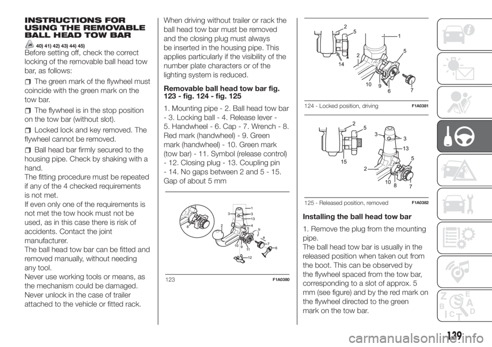
40) 41) 42) 43) 44) 45)Before setting off, check the correct
locking of the removable ball head tow
bar, as follows:
The green mark of the flywheel must
coincide with the green mark on the
tow bar.
The flywheel is in the stop position
on the tow bar (without slot).
Locked lock and key removed. The
flywheel cannot be removed.
Ball head bar firmly secured to the
housing pipe. Check by shaking with a
hand.
The fitting procedure must be repeated
if any of the 4 checked requirements
is not met.
If even only one of the requirements is
not met the tow hook must not be
used, as in this case there is risk of
accidents. Contact the joint
manufacturer.
The ball head tow bar can be fitted and
removed manually, without needing
any tool.
Never use working tools or means, as
the mechanism could be damaged.
Never unlock in the case of trailer
attached to the vehicle or fitted rack.When driving without trailer or rack the
ball head tow bar must be removed
and the closing plug must always
be inserted in the housing pipe. This
applies particularly if the visibility of the
number plate characters or of the
lighting system is reduced.
Removable ball head tow bar fig.
123 - fig. 124 - fig. 125
1. Mounting pipe - 2. Ball head tow bar
- 3. Locking ball - 4. Release lever -
5. Handwheel - 6. Cap - 7. Wrench - 8.
Red mark (handwheel) - 9. Green
mark (handwheel) - 10. Green mark
(tow bar) - 11. Symbol (release control)
- 12. Closing plug - 13. Coupling pin
- 14. No gaps between 2 and5-15.
Gap of about 5 mm
Installing the ball head tow bar
1. Remove the plug from the mounting
pipe.
The ball head tow bar is usually in the
released position when taken out from
the boot. This can be observed by
the flywheel spaced from the tow bar,
corresponding to a slot of approx. 5
mm (see figure) and by the red mark on
the flywheel directed to the green
mark on the tow bar.
123F1A0380
124 - Locked position, drivingF1A0381
125 - Released position, removedF1A0382
139
Page 145 of 296
REPLACING A BULB
GENERAL
INSTRUCTIONS
139) 140)
46)
When a light is not working, check
that the corresponding fuse is intact
before changing a bulb. For the location
of fuses, refer to the paragraph
"Replacing fuses" in this chapter.
before changing a bulb check the
contacts for oxidation;
burnt bulbs must be replaced by
others of the same type and power;
always check the headlight beam
direction after changing a bulb;
IMPORTANT A slight misting may
appear on the internal surface of the
headlight: this does not indicate a fault
and is caused by low temperature
and the degree of humidity in the air.
Misting will rapidly disappear when the
headlights are switched on. The
presence of drops inside the headlights
indicates infiltration of water. Contact
a Fiat Dealership.
WARNING
139)Modifications or repairs to the
electric system that are not carried out
properly or do not take the system
technical specifications into account can
cause malfunctions leading to the risk
of fire.
140)Halogen bulbs contain pressurised
gas, in the case of breakage they may
burst causing glass fragments to be
projected outwards.
WARNING
46)Halogen bulbs must be handled
holding the metallic part only. Touching the
transparent part of the bulb with your
fingers may reduce the intensity of the
emitted light and even reduce the lifespan
of the bulb. In the event of accidental
contact, wipe the bulb with a cloth
moistened with alcohol and let the bulb
dry.
143
Page 171 of 296
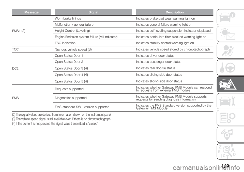
Message Signal Description
FMS1(2)
Worn brake linings Indicates brake pad wear warning light on
Malfunction / general failure Indicates general failure warning light on
Height Control (Levelling) Indicates self-levelling suspension indicator displayed
Engine Emission system failure (Mil indicator) Indicates particulate filter blocked warning light on
ESC indication Indicates stability control warning light on
TC01
Tachogr. vehicle speed
(3)Indicates vehicle speed stored by chronotachograph
DC2Open Status Door 1 Indicates driver door status
Open Status Door 2 Indicates passenger door status
Open Status Door 3
(4)Indicates rear door(s) status
Open Status Door 4
(4)Indicates sliding side door status
Open Status Door 5
(4)Indicates sliding side door status
FMSRequests supportedIndicates whether Gateway FMS Module can respond
to requests from external FMS module
Diagnostics supportedIndicates whether Gateway FMS Module supports
requests for sending diagnosis information
FMS-standard SW - version supportedIndicates the FMS Standard version supported by the
Gateway FMS Module
(2) The signal values are derived from information shown on the instrument panel
(3) The vehicle speed signal is still available even if there is no chronotachograph
(4) If the content is not present, the signal value transmitted is ‘closed’
169
Page 174 of 296
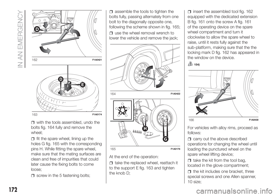
with the tools assembled, undo the
bolts fig. 164 fully and remove the
wheel;
fit the spare wheel, lining up the
holes G fig. 165 with the corresponding
pins H. While fitting the spare wheel,
make sure that the mating surfaces are
clean and free of impurities that could
later cause the fixing bolts to come
loose;
screw in the 5 fastening bolts;
assemble the tools to tighten the
bolts fully, passing alternately from one
bolt to the diagonally opposite one,
following the scheme shown in fig. 165;
use the wheel removal wrench to
lower the vehicle and remove the jack;
At the end of the operation:
take the replaced wheel, reattach it
to the support E fig. 163 and tighten
the knob D;
insert the assembled tool fig. 162
equipped with the dedicated extension
B fig. 161 onto the screw A fig. 161
of the operating device on the spare
wheel compartment and turn it
clockwise to allow the spare wheel to
raise, until it rests fully against the
sub-platform, making sure that the the
locking mark D fig. 162 has appeared in
the window on the device.
154)
For vehicles with alloy rims, proceed as
follows:
carry out the above described
operations for changing the wheel until
loading the punctured wheel on the
spare wheel lifting device;
take the kit from the tool bag,
located in the glove compartment;
the kit includes one bracket, three
special screws and one Allen spanner,
10 size;
162F1A0421
163F1A0174
164F1A0422
G
H
165F1A0176
166F1A0430
172
IN AN EMERGENCY
Page 189 of 296
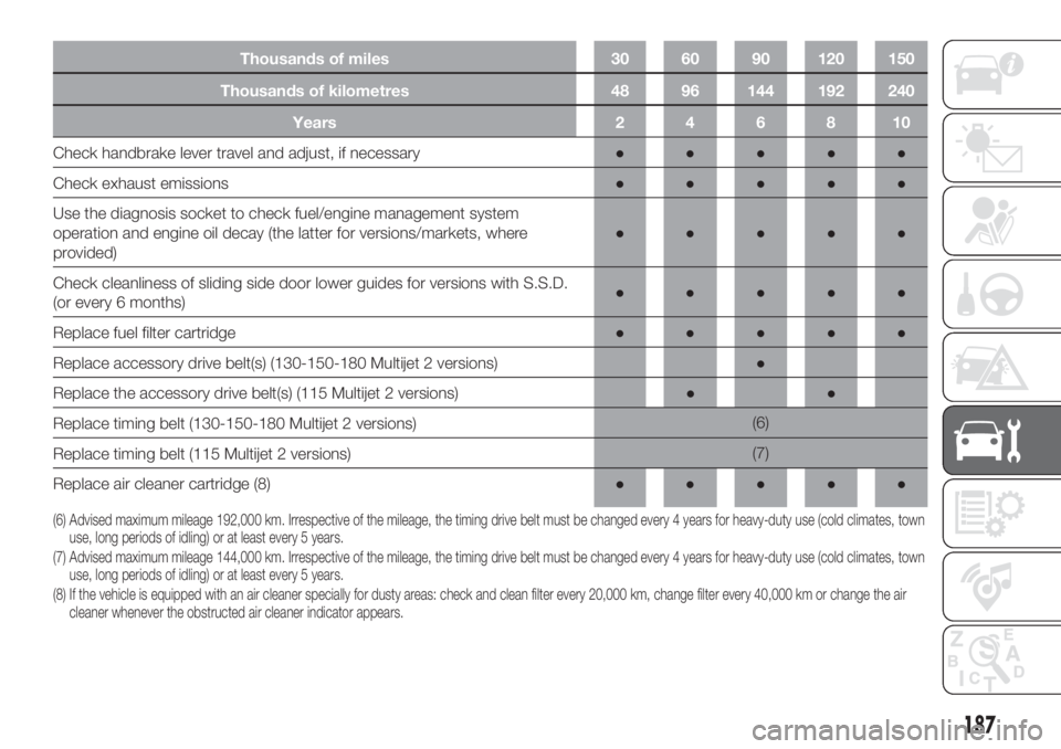
Thousands of kilometres 48 96 144 192 240
Years 2 4 6 8 10
Check handbrake lever travel and adjust, if necessary●●●●●
Check exhaust emissions●●●●●
Use the diagnosis socket to check fuel/engine management system
operation and engine oil decay (the latter for versions/markets, where
provided)●●●●●
Check cleanliness of sliding side door lower guides for versions with S.S.D.
(or every 6 months)●●●●●
Replace fuel filter cartridge●●●●●
Replace accessory drive belt(s) (130-150-180 Multijet 2 versions)●
Replace the accessory drive belt(s) (115 Multijet 2 versions)●●
Replace timing belt (130-150-180 Multijet 2 versions)(6)
Replace timing belt (115 Multijet 2 versions)(7)
Replace air cleaner cartridge (8)●●●●●
(6) Advised maximum mileage 192,000 km. Irrespective of the mileage, the timing drive belt must be changed every 4 years for heavy-duty use (cold climates, town
use, long periods of idling) or at least every 5 years.
(7) Advised maximum mileage 144,000 km. Irrespective of the mileage, the timing drive belt must be changed every 4 years for heavy-duty use (cold climates, town
use, long periods of idling) or at least every 5 years.
(8) If the vehicle is equipped with an air cleaner specially for dusty areas: check and clean filter every 20,000 km, change filter every 40,000 km or change the air
cleaner whenever the obstructed air cleaner indicator appears.
187
Thousands of miles 30 60 90 120 150
Page 190 of 296
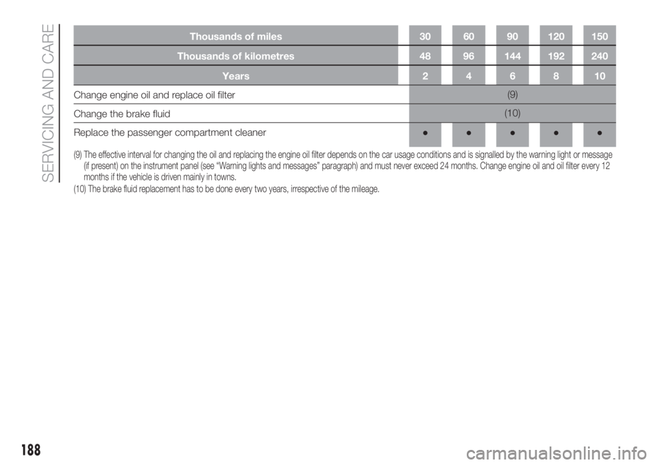
Thousands of kilometres 48 96 144 192 240
Years 2 4 6 8 10
Change engine oil and replace oil filter(9)
Change the brake fluid(10)
Replace the passenger compartment cleaner●●●●●
(9) The effective interval for changing the oil and replacing the engine oil filter depends on the car usage conditions and is signalled by the warning light or message
(if present) on the instrument panel (see “Warning lights and messages” paragraph) and must never exceed 24 months. Change engine oil and oil filter every 12
months if the vehicle is driven mainly in towns.
(10) The brake fluid replacement has to be done every two years, irrespective of the mileage.
188
SERVICING AND CARE
Thousands of miles 30 60 90 120 150
Page 192 of 296
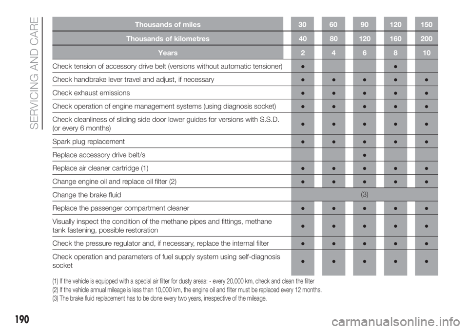
Thousands of kilometres 40 80 120 160 200
Years246810
Check tension of accessory drive belt (versions without automatic tensioner)●●
Check handbrake lever travel and adjust, if necessary●●●●●
Check exhaust emissions●●●●●
Check operation of engine management systems (using diagnosis socket)●●●●●
Check cleanliness of sliding side door lower guides for versions with S.S.D.
(or every 6 months)●●●●●
Spark plug replacement●●●●●
Replace accessory drive belt/s●
Replace air cleaner cartridge (1)●●●●●
Change engine oil and replace oil filter (2)●●●●●
Change the brake fluid(3)
Replace the passenger compartment cleaner●●●●●
Visually inspect the condition of the methane pipes and fittings, methane
tank fastening, possible restoration●●●●●
Check the pressure regulator and, if necessary, replace the internal filter●●●●●
Check operation and parameters of fuel supply system using self-diagnosis
socket●●●●●
(1) If the vehicle is equipped with a special air filter for dusty areas: - every 20,000 km, check and clean the filter
(2) If the vehicle annual mileage is less than 10,000 km, the engine oil and filter must be replaced every 12 months.
(3) The brake fluid replacement has to be done every two years, irrespective of the mileage.
190
SERVICING AND CARE
Thousands of miles 30 60 90 120 150