headlights FIAT DUCATO BASE CAMPER 2018 Owner handbook (in English)
[x] Cancel search | Manufacturer: FIAT, Model Year: 2018, Model line: DUCATO BASE CAMPER, Model: FIAT DUCATO BASE CAMPER 2018Pages: 304, PDF Size: 14.93 MB
Page 78 of 304
 What it means What to do
greenCRUISE CONTROL
(for versions/markets, where provided)
On turning the key to the MAR position, the warning
light on the display turns on, but it must turn off after a
few")
What it means What to do
greenCRUISE CONTROL
(for versions/markets, where provided)
On turning the key to the MAR position, the warning
light on the display turns on, but it must turn off after a
few seconds if the Cruise Control is disabled.
The warning light is lit up on the display by turning the
Cruise Control selector wheel to ON or, according
to the versions. On certain versions a dedicated
message is displayed.
greenSPEED LIMITER
(for versions/markets, where provided)
The warning light on the dial switches on when the
function is activated.
On certain versions a dedicated message is displayed.
greenAUTOMATIC MAIN BEAM HEADLIGHTS
This warning light comes on when the automatic main
beam headlights are activated.
blueMAIN BEAM HEADLIGHTS
The warning light switches on when the main beam
headlights are turned on.
76
KNOWING THE INSTRUMENT PANEL
Page 80 of 304
 Messages on display
What it means What to do
EXTERIOR LIGHTS FAILURE
(Versions with reconfigurable multifunction display)
The symbol switches on when a fault is detected on
one of the following lights")
Messages on display
What it means What to do
EXTERIOR LIGHTS FAILURE
(Versions with reconfigurable multifunction display)
The symbol switches on when a fault is detected on
one of the following lights:
direction indicators
rear fog lights
brake lights
side lights
daytime running lights
number plate lights
reversing lights
main beam automatism
trailer side lights
trailer direction indicators.The fault relating to these lights could be: one or more
blown bulbs, a blown protection fuse or a break in the
electrical connection.
LOW ENGINE OIL PRESSURE WARNING LIGHT
FAILURE
The symbol turns on to indicate a failure of the low
engine oil pressure warning light.Contact a Fiat Dealership.
BRAKE LIGHT FAILURE
(Versions with reconfigurable multifunction display)
The symbol switches on when a fault is detected in the
brake lights.The fault could be: one or more blown bulbs, a blown
protection fuse or a break in the electrical connection.
MAIN BEAM AUTOMATISM FAULT
(Versions with reconfigurable multifunction display)
The symbol switches on when a fault is detected in the
automatic switching-on system for the main beam
headlights.
78
KNOWING THE INSTRUMENT PANEL
Page 133 of 304
 TRAFFIC SIGN
RECOGNITION
(for versions/markets, where provided)
125) 126) 127) 128)
28) 29) 30) 31) 32) 33) 34)
The system automatically detects the
recognisable traffic signs: speed limits,
no overta")
TRAFFIC SIGN
RECOGNITION
(for versions/markets, where provided)
125) 126) 127) 128)
28) 29) 30) 31) 32) 33) 34)
The system automatically detects the
recognisable traffic signs: speed limits,
no overtaking signs and signs indicating
the end of such prohibitions.
The camera is fitted behind the internal
rear view mirror. The sensor always
checks the traffic signs indicating the
current speed limit and possible no
overtaking signs.
IMPORTANT The system is designed to
read signs complying with the
specifications of the Vienna convention.
USE OF THE TRAFFIC
SIGN RECOGNITION
System switching on and off
The system can be activated/
deactivated using the display menu.
Refer to the "Display" paragraph in the
"Knowing the instrument panel"
chapter.
Note: The system state and settings do
not change throughout the various
on-off cycles.
WARNING
125)If the camera loses its position due to
a load variation, the system may not work
temporarily to allow the camera to perform
an auto-calibration.
126)The system only detects the preset
traffic signs. If the minimum visibility
conditions and distance from the sign are
met it can detect all traffic signs.
127)The system is a driving assistance
system but it does not relieve the driver of
the responsibility of driving with due
attention and diligence in compliance with
the laws in force.
128)When the system is active, the driver
is responsible for controlling the vehicle
and monitoring the system, and must
intervene as appropriate if necessary.
WARNING
28)In the event of errors the system may
not work.
29)At low temperatures and in particularly
adverse weather conditions, the system
may not work.
30)Rain, snow, splashes and strong light
contrast may influence the sensor.
31)Do not repair the area of the
windscreen directly surrounding the sensor.
32)If the vehicle is equipped with a
non-genuine suspension kit, the system
may not work correctly.
33)Always use genuine spare parts when
replacing the bulbs of the headlights. Other
bulbs may reduce the system
performance.
34)Clean the windscreen from foreign
matters such as bird droppings, insects,
snow or ice.
100
136F1A0373
131
Page 151 of 304
 REPLACING A BULB
GENERAL
INSTRUCTIONS
140) 141)
47)
When a light is not working, check
that the corresponding fuse is intact
before changing a bulb. For the location
of fuses, refer to the paragraph
&")
REPLACING A BULB
GENERAL
INSTRUCTIONS
140) 141)
47)
When a light is not working, check
that the corresponding fuse is intact
before changing a bulb. For the location
of fuses, refer to the paragraph
"Replacing fuses" in this chapter.
before changing a bulb check the
contacts for oxidation;
burnt bulbs must be replaced by
others of the same type and power;
always check the headlight beam
direction after changing a bulb;
IMPORTANT A slight misting may
appear on the internal surface of the
headlight: this does not indicate a fault
and is caused by low temperature
and the degree of humidity in the air.
Misting will rapidly disappear when the
headlights are switched on. The
presence of drops inside the headlights
indicates infiltration of water. Contact
a Fiat Dealership.
WARNING
140)Modifications or repairs to the
electric system that are not carried out
properly or do not take the system
technical specifications into account can
cause malfunctions leading to the risk
of fire.
141)Halogen bulbs contain pressurised
gas, in the case of breakage they may
burst causing glass fragments to be
projected outwards.
WARNING
47)Halogen bulbs must be handled
holding the metallic part only. Touching the
transparent part of the bulb with your
fingers may reduce the intensity of the
emitted light and even reduce the lifespan
of the bulb. In the event of accidental
contact, wipe the bulb with a cloth
moistened with alcohol and let the bulb
dry.
149
Page 153 of 304
 Light bulbs
 Type Power Figure ref.
Main beam headlights H7 55W D
Dipped beam headlights H7 55W D
Front side lights / daytime running lights
W21/5W - LED
(#)--
Front fog lights
(*)H11 55W -")
Light bulbs
Light bulbs Type Power Figure ref.
Main beam headlights H7 55W D
Dipped beam headlights H7 55W D
Front side lights / daytime running lights
W21/5W - LED
(#)--
Front fog lights
(*)H11 55W -
Front direction indicators WY21W 21W B
Side turn lightW16WF
(**) / WY5W
(***)16W(**) / 5W (***)A
Rear direction indicators PY2IW 21W B
Side lights W5W 5W A
Rear side lights P21/5W 21/5W B
Rear side lights/Brake lights P21W 21W B
Third brake light W5W 5W B
Reverse gear W16W 16W B
Rear fog light W16W 16W B
Number plate C5W 5W A
Front roof light (movable lens) 12V10W 10W C
Rear ceiling light 12V10W 10W C
(#) where provided, instead of bulb W21/5W
(*)for versions/markets, where provided
(**)XL and Tempo Libero versions
(***)all other versions
151
Page 154 of 304
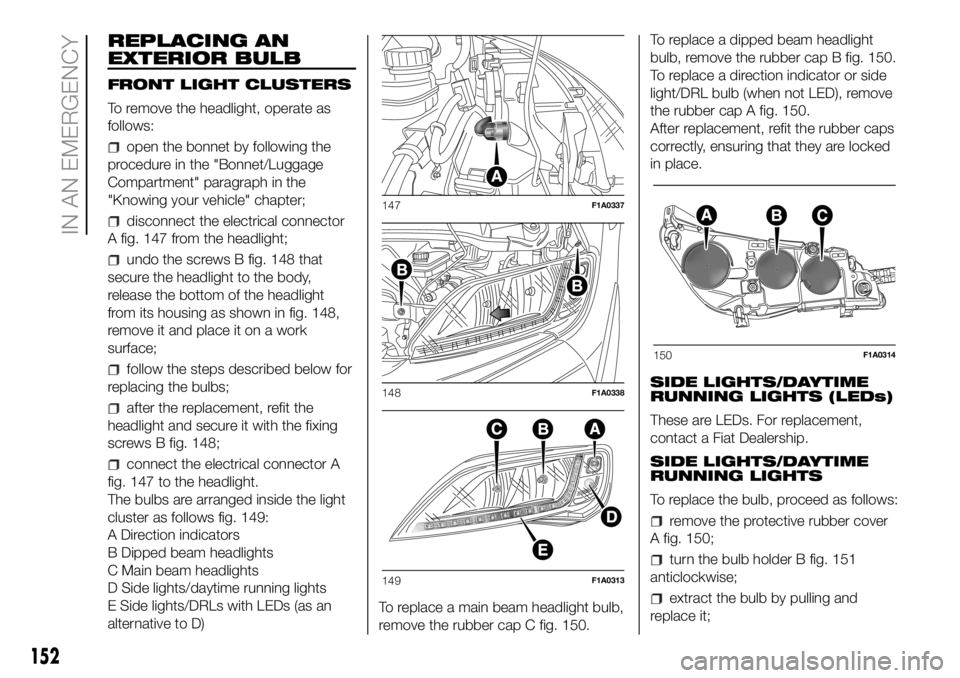
REPLACING AN
EXTERIOR BULB
FRONT LIGHT CLUSTERS
To remove the headlight, operate as
follows:
open the bonnet by following the
procedure in the "Bonnet/Luggage
Compartment" paragraph in the
"Knowing your vehicle" chapter;
disconnect the electrical connector
A fig. 147 from the headlight;
undo the screws B fig. 148 that
secure the headlight to the body,
release the bottom of the headlight
from its housing as shown in fig. 148,
remove it and place it on a work
surface;
follow the steps described below for
replacing the bulbs;
after the replacement, refit the
headlight and secure it with the fixing
screws B fig. 148;
connect the electrical connector A
fig. 147 to the headlight.
The bulbs are arranged inside the light
cluster as follows fig. 149:
A Direction indicators
B Dipped beam headlights
C Main beam headlights
D Side lights/daytime running lights
E Side lights/DRLs with LEDs (as an
alternative to D)To replace a main beam headlight bulb,
remove the rubber cap C fig. 150.To replace a dipped beam headlight
bulb, remove the rubber cap B fig. 150.
To replace a direction indicator or side
light/DRL bulb (when not LED), remove
the rubber cap A fig. 150.
After replacement, refit the rubber caps
correctly, ensuring that they are locked
in place.
SIDE LIGHTS/DAYTIME
RUNNING LIGHTS (LEDs)
These are LEDs. For replacement,
contact a Fiat Dealership.
SIDE LIGHTS/DAYTIME
RUNNING LIGHTS
To replace the bulb, proceed as follows:
remove the protective rubber cover
A fig. 150;
turn the bulb holder B fig. 151
anticlockwise;
extract the bulb by pulling and
replace it;
147F1A0337
148F1A0338
149F1A0313
150F1A0314
152
IN AN EMERGENCY
Page 155 of 304
 remove the bulb by pushing it
slightly and turning it anticlockwise
(bayonet mount);
refit the bulb holder B by turning it
clockwise and making sure that it locks
correctly
refit the protective rubber")
remove the bulb by pushing it
slightly and turning it anticlockwise
(bayonet mount);
refit the bulb holder B by turning it
clockwise and making sure that it locks
correctly
refit the protective rubber cover A
fig. 150.
MAIN BEAM HEADLIGHTSTo replace the bulb, proceed as follows:
remove the protective rubber cover
C fig. 150;
free the bulb holder A fig. 152 from
the side clips B and remove it;
disconnect the electrical connector;
fit the new bulb, ensuring that the
outline of the metal part coincides with
the grooves on the curve of the
headlight, pressing to engage it with the
side clips;
reconnect the electrical connector;
refit the protective rubber cover
C fig. 150.
DIPPED BEAM
HEADLIGHTS
With incandescent bulbs
To replace the bulb, proceed as follows:
remove the protective rubber cover
B fig. 150;
free the bulb holder A fig. 153 from
the side clips B and remove it;
disconnect the electrical connector;
fit the new bulb, ensuring that the
outline of the metal part coincides with
the grooves on the curve of the
headlight, pressing to engage it with the
side clips;
reconnect the electrical connector;
refit the protective rubber cover
B fig. 150.
DIRECTION INDICATORS
To replace the bulb, proceed as follows:
remove the protective rubber cover
A fig. 150;
turn the bulb holder B fig. 154
anticlockwise;
extract the bulb by pulling and
replace it;
remove the bulb by pushing it
slightly and turning it anticlockwise
(bayonet mount);
refit the bulb holder B by turning it
clockwise and making sure that it locks
correctly
refit the protective rubber cover A
fig. 150.
151F1A0386
152F1A0315
153F1A0316
153
Page 188 of 304
 IMPORTANT After an accident,
remember to remove the key from the
ignition device to prevent the battery
from running down. If no fuel leaks
or damage to vehicle's electrical
devices (e.g. headligh")
IMPORTANT After an accident,
remember to remove the key from the
ignition device to prevent the battery
from running down. If no fuel leaks
or damage to vehicle's electrical
devices (e.g. headlights) are detected
after the impact and the vehicle is
able to set off again, reactivate the
automatic fuel cut-off switch.
Restoring the fuel cut-off switch
Press button A fig. 202 to reactivate the
fuel cut off switch.
WARNING
174)If, after an impact, you smell fuel or
notice leaks from the fuel system, do
not reactivate the switch to avoid the risk
of fire.
175)Before reactivating the fuel cut-off
switch, carefully check for fuel leaks or
damage to the vehicle's electrical devices
(e.g. headlights).
TOWING THE
VEHICLE
176) 177) 178) 179) 180) 181) 182) 183) 184)
The vehicle is equipped with two rings
for attaching the tow hook.
The front ring is located in the tool box
beneath the passenger side seat. On
versions with Fix&Go kit and without
spare wheel, the tool box is available
only on request for versions/markets
where provided.
202F1A0086
203F1A0221
204F1A0222
186
IN AN EMERGENCY
Page 194 of 304
 SERVICE SCHEDULE
The checks listed in the Service Schedule, after reaching 144,000 km/6 years (130 - 150 - 180 Multijet 2 versions) 192,000
km/8 years (115 Multijet 2 versions), must be cyclically rep")
SERVICE SCHEDULE
The checks listed in the Service Schedule, after reaching 144,000 km/6 years (130 - 150 - 180 Multijet 2 versions) 192,000
km/8 years (115 Multijet 2 versions), must be cyclically repeated starting from the first interval, thus following the same intervals
as before.
The checks listed in the Service Schedule, after reaching 90,000 mi/6 years (130 - 150 - 180 Multijet 2 versions) 120,000 mi/8
years (115 Multijet 2 versions), must be cyclically repeated starting from the first interval, thus following the same intervals as
before.
Thousands of miles 30 60 90 120 150
Thousands of kilometres 48 96 144 192 240
Years 2 4 6 8 10
Check battery charge status and possibly recharge●●●●●
Check tyre condition/wear and adjust pressure, if necessary; check the
expiry date of the “Fix & Go Automatic” repair kit (for versions/markets,
where provided)●●●●●
Check operation of lighting system (headlights, direction indicators, hazard
warning lights, boot, passenger compartment, glove compartment,
instrument panel warning lights, etc.)●●●●●
Check operation of the windscreen wiper/washer system and adjust jets, if
necessary●●●●●
Check windscreen/rearscreen wiper blade position/wear (for markets/
versions, where provided)●●●●●
Check cleanliness of bonnet and luggage compartment locks, cleanliness
and lubrication of linkage●●●●●
Visually inspect conditions of: exterior bodywork, underbody protection,
pipes and hoses (exhaust, fuel system, brakes), rubber elements (gaiters,
sleeves, bushes, etc.)●●●●●
192
SERVICING AND CARE
Page 198 of 304
 Natural Power versions
Thousands of miles 25 50 75 100 125
Thousands of kilometres 40 80 120 160 200
Years246810
Check battery charge status and possibly recharge●●●●●
Check tyreconditions/w")
Natural Power versions
Thousands of miles 25 50 75 100 125
Thousands of kilometres 40 80 120 160 200
Years246810
Check battery charge status and possibly recharge●●●●●
Check tyreconditions/wear and adjust pressure, if necessary●●●●●
Check operation of lighting system (headlights, direction indicators, hazard
warning lights, boot, passenger compartment, glove compartment,
instrument panel warning lights, etc.)●●●●●
Check operation of the windscreen wiper/washer system and adjust jets, if
necessary●●●●●
Check the position/wear of the windscreen/rear window wiper blades●●●●●
Check cleanliness of bonnet and luggage compartment locks, cleanliness
and lubrication of linkage●●●●●
Visually inspect conditions of: exterior bodywork, underbody protection,
pipes and hoses (exhaust, fuel system, brakes), rubber elements (gaiters,
sleeves, bushes, etc.)●●●●●
Visually inspect conditions and wear of front disc brake pads and operation
of pad wear indicator●●●●●
Visually inspect condition and wear of rear disc brake pads and operation of
pad wear indicator (for versions/markets, where provided)●●●●●
Check and, if necessary, top up fluid levels (engine coolant, hydraulic clutch/
brakes, windscreen washer, battery, etc.)●●●●●
196
SERVICING AND CARE