160 FIAT DUCATO BASE CAMPER 2018 Owner handbook (in English)
[x] Cancel search | Manufacturer: FIAT, Model Year: 2018, Model line: DUCATO BASE CAMPER, Model: FIAT DUCATO BASE CAMPER 2018Pages: 304, PDF Size: 14.93 MB
Page 117 of 304
SIDE BAGS
102) 103) 104) 105) 106) 107) 108) 109) 110) 111)
112) 113) 114) 115)
To help increase occupant protection in
the event of a side impact, for
versions/markets where provided, the
car is equipped with front side bags
and window bags.
Side bags (for versions/markets where
provided) protect occupants from
side impacts of medium-high severity,
by placing the bag between the
occupant and the internal parts of the
side structure of the vehicle. Non-
activation of side bags in other types of
collisions (front collisions, rear shunts,
roll-overs, etc.) is not a system
malfunction.
An electronic control unit causes the
bags to inflate in the event of a side-on
collision. The bags inflate
instantaneously, placing themselves
between the occupant's body and the
structures which could cause injury.
They deflate immediately afterwards.
Side bags (for versions/markets where
provided) are not a replacement of
but complementary to the belts, which
you are recommended to always wear,
as specified by law in Europe and
most non-European countries.FRONT SIDE BAGS FOR
CHEST PROTECTION
(for versions/markets, where provided)
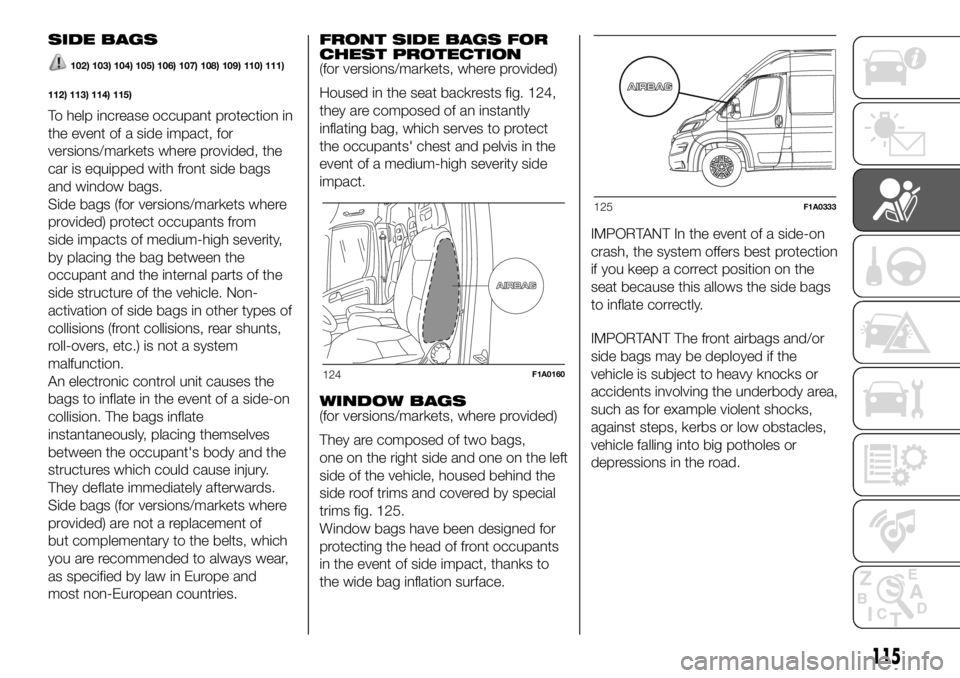
Housed in the seat backrests fig. 124,
they are composed of an instantly
inflating bag, which serves to protect
the occupants' chest and pelvis in the
event of a medium-high severity side
impact.
WINDOW BAGS
(for versions/markets, where provided)
They are composed of two bags,
one on the right side and one on the left
side of the vehicle, housed behind the
side roof trims and covered by special
trims fig. 125.
Window bags have been designed for
protecting the head of front occupants
in the event of side impact, thanks to
the wide bag inflation surface.IMPORTANT In the event of a side-on
crash, the system offers best protection
if you keep a correct position on the
seat because this allows the side bags
to inflate correctly.
IMPORTANT The front airbags and/or
side bags may be deployed if the
vehicle is subject to heavy knocks or
accidents involving the underbody area,
such as for example violent shocks,
against steps, kerbs or low obstacles,
vehicle falling into big potholes or
depressions in the road.
124F1A0160
125F1A0333
115
Page 156 of 304
Side
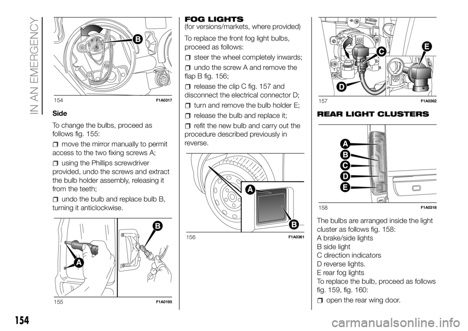
To change the bulbs, proceed as
follows fig. 155:
move the mirror manually to permit
access to the two fixing screws A;
using the Phillips screwdriver
provided, undo the screws and extract
the bulb holder assembly, releasing it
from the teeth;
undo the bulb and replace bulb B,
turning it anticlockwise.FOG LIGHTS
(for versions/markets, where provided)
To replace the front fog light bulbs,
proceed as follows:
steer the wheel completely inwards;
undo the screw A and remove the
flap B fig. 156;
release the clip C fig. 157 and
disconnect the electrical connector D;
turn and remove the bulb holder E;
release the bulb and replace it;
refit the new bulb and carry out the
procedure described previously in
reverse.REAR LIGHT CLUSTERS
The bulbs are arranged inside the light
cluster as follows fig. 158:
A brake/side lights
B side light
C direction indicators
D reverse lights.
E rear fog lights
To replace the bulb, proceed as follows
fig. 159, fig. 160:
open the rear wing door.
154F1A0317
155F1A0195
156F1A0361
157F1A0362
158F1A0318
154
IN AN EMERGENCY
Page 157 of 304
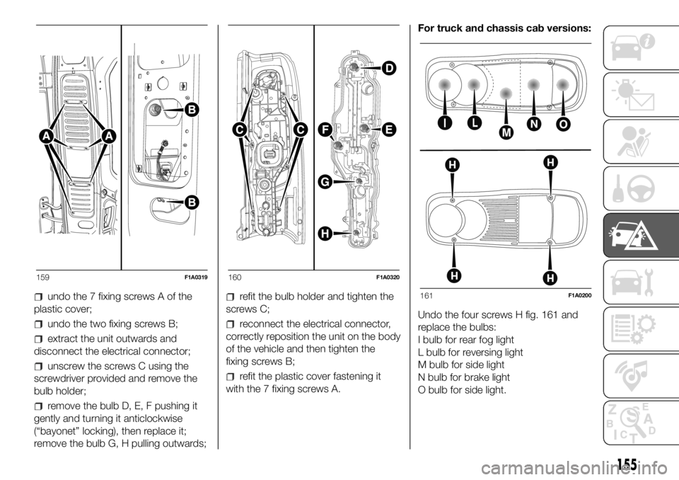
undo the 7 fixing screws A of the
plastic cover;
undo the two fixing screws B;
extract the unit outwards and
disconnect the electrical connector;
unscrew the screws C using the
screwdriver provided and remove the
bulb holder;
remove the bulb D, E, F pushing it
gently and turning it anticlockwise
(“bayonet” locking), then replace it;
remove the bulb G, H pulling outwards;
refit the bulb holder and tighten the
screws C;
reconnect the electrical connector,
correctly reposition the unit on the body
of the vehicle and then tighten the
fixing screws B;
refit the plastic cover fastening it
with the 7 fixing screws A.For truck and chassis cab versions:
Undo the four screws H fig. 161 and
replace the bulbs:
I bulb for rear fog light
L bulb for reversing light
M bulb for side light
N bulb for brake light
O bulb for side light.
159F1A0319160F1A0320
161F1A0200
155
Page 162 of 304
Optional wiring module 2
RIGHT CENTRAL PILLAR
OPTIONAL FUSEBOX
(for versions/markets, where provided)
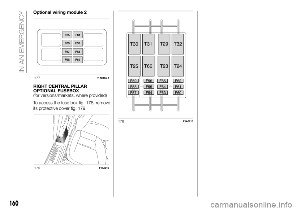
To access the fuse box fig. 178, remove
its protective cover fig. 179.
177F1A0455-1
179F1A0217
178F1A0218
160
IN AN EMERGENCY
Page 181 of 304
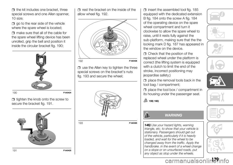
the kit includes one bracket, three
special screws and one Allen spanner,
10 size;
go to the rear side of the vehicle
where the spare wheel is located;
make sure that all of the cable for
the spare wheel lifting device has been
unrolled, grip the bell and position it
inside the circular bracket fig. 190;
tighten the knob onto the screw to
secure the bracket fig. 191.
rest the bracket on the inside of the
allow wheel fig. 192.
use the Allen key to tighten the three
special screws on the bracket's nuts
fig. 193 and secure the wheel;
insert the assembled tool fig. 185
equipped with the dedicated extension
B fig. 184 onto the screw A fig. 184
of the operating device on the spare
wheel compartment and turn it
clockwise to allow the spare wheel to
raise, until it rests fully against the
sub-platform, making sure that the the
locking mark D fig. 187 has appeared in
the window on the device.
Check that the position of the
replaced wheel under the platform is
correct (the lifting system is equipped
with a clutch to limit the end of the
stroke, incorrect positioning may
jeopardise safety;)
place the removal tools back in the
tool bag / compartment;
place the tool box / compartment in
its housing under the passenger seat.
159) 160)
WARNING
146)Use your hazard lights, warning
triangle, etc. to show that your vehicle is
stationary. Passengers should get out
of the vehicle, particularly if it is heavily
loaded, and wait for the wheel to be
changed away from the traffic. Apply the
handbrake. in the event of a wheel change
on a slope or on unsurfaced roads, put
any object as stop under the wheels.
190F1A0424
191F1A0425
192F1A0426
193F1A0385
179
Page 182 of 304
147)The spare wheel supplied (for
versions/markets, where provided) is
specific for your vehicle. Therefore, it must
not be used on other models. Do not
use spare wheels of other models on your
vehicle. The wheel bolts are specific for
your vehicle: do not use them on different
models and do not use bolts from other
models on your car.
148)Repair and refit the standard wheel as
soon as possible. Do not apply grease to
the bolt threads before fitting: they could
come unscrewed.
149)Use the jack only to replace wheels
on the vehicle with which it is supplied
or on other vehicles of the same model.
Never use the jack for other purposes,
such as lifting other vehicle models. Never
use the jack to carry out repairs under
the vehicle. Incorrect positioning of the jack
may cause the lifted vehicle to fall. Do not
use the jack for loads higher than the
one shown on its label.
150)Never tamper with the inflation valve.
Never introduce tools of any kind between
rim and tyre. Check tyre and spare wheel
pressure regularly, referring to the values
shown in the "Technical specifications"
section.
151)No tools other than the crank
provided should be used with the spare
wheel lifting device; it should be operated
by hand only.
152)On versions equipped with self-
levelling air suspension, never introduce the
head or hands in the wheel arch: the
vehicle could raise or lower automatically
depending on possible load or temperature
changes.153)The device should only be operated
by hand, without using any type of tool
other than the crank provided like
pneumatic or electrical screwers.
154)The moving components of the jack
(screws and joints) can also cause injuries:
avoid touching them. If you come into
contact with lubricating grease, clean
yourself thoroughly.
155)The jack should be used on level firm
ground wherever possible.
156)It is recommended that the wheels of
the vehicle be chocked, and that no person
should remain in a vehicle that is being
jacked.
157)No person should place any portion of
their body under a vehicle that is
supported by a jack.
158)At the end of the operation of
raising/locking the spare wheel, after
checking that the wheel is positioned
correctly under the platform (yellow notch
inside the window on the device), extract
the operating wrench. Take care not to turn
the wrench in the wrong direction (as in
fig. 189) to facilitate extracting it, to prevent
the attachment device from being
released and to ensure that the wheel
assembly remains safely fastened.
159)Each time the spare wheel is moved,
check that it is correctly positioned in its
housing under the platform. If it is not
correctly positioned, this could adversely
affect safety.
160)The spare wheel lifting device is
equipped with a clutch safety system for its
own protection; this could activated if an
excessive load is applied on the
maneuvering screw.FIX&GO
AUTOMATIC QUICK
TYRE REPAIR KIT
(for versions/markets, where provided)
The Fix & Go automatic quick tyre
repair kit is located at the front of the
vehicle passenger compartment and
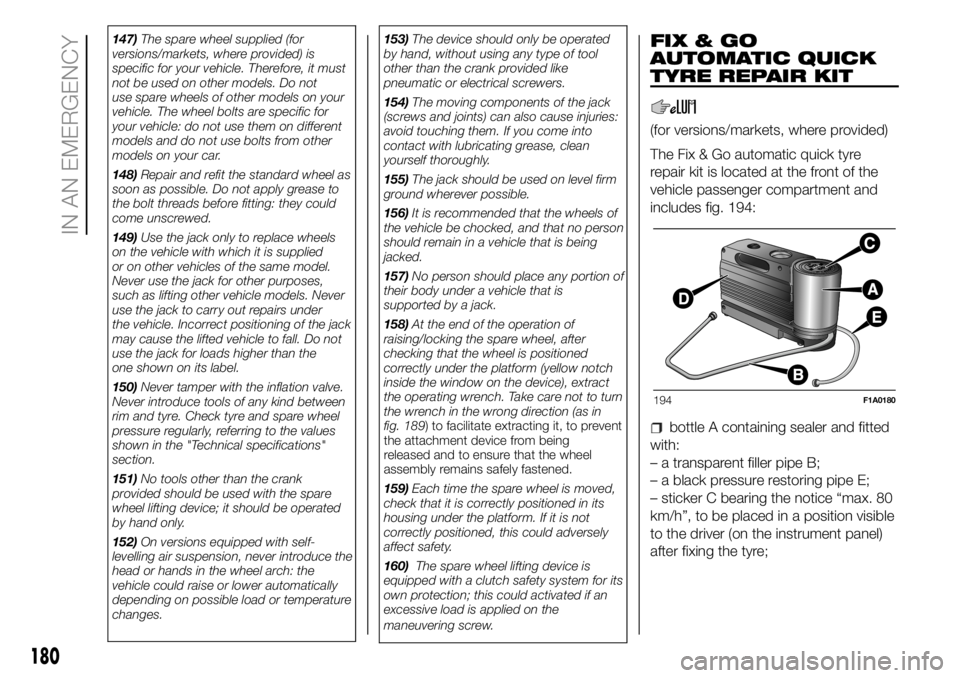
includes fig. 194:
bottle A containing sealer and fitted
with:
– a transparent filler pipe B;
– a black pressure restoring pipe E;
– sticker C bearing the notice “max. 80
km/h”, to be placed in a position visible
to the driver (on the instrument panel)
after fixing the tyre;
194F1A0180
180
IN AN EMERGENCY
Page 198 of 304
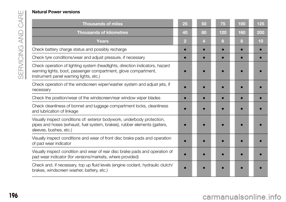
Natural Power versions
Thousands of miles 25 50 75 100 125
Thousands of kilometres 40 80 120 160 200
Years246810
Check battery charge status and possibly recharge●●●●●
Check tyreconditions/wear and adjust pressure, if necessary●●●●●
Check operation of lighting system (headlights, direction indicators, hazard
warning lights, boot, passenger compartment, glove compartment,
instrument panel warning lights, etc.)●●●●●
Check operation of the windscreen wiper/washer system and adjust jets, if
necessary●●●●●
Check the position/wear of the windscreen/rear window wiper blades●●●●●
Check cleanliness of bonnet and luggage compartment locks, cleanliness
and lubrication of linkage●●●●●
Visually inspect conditions of: exterior bodywork, underbody protection,
pipes and hoses (exhaust, fuel system, brakes), rubber elements (gaiters,
sleeves, bushes, etc.)●●●●●
Visually inspect conditions and wear of front disc brake pads and operation
of pad wear indicator●●●●●
Visually inspect condition and wear of rear disc brake pads and operation of
pad wear indicator (for versions/markets, where provided)●●●●●
Check and, if necessary, top up fluid levels (engine coolant, hydraulic clutch/
brakes, windscreen washer, battery, etc.)●●●●●
196
SERVICING AND CARE
Page 199 of 304
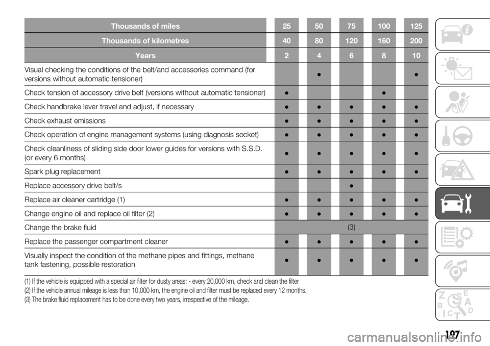
Thousands of miles 25 50 75 100 125
Thousands of kilometres 40 80 120 160 200
Years246810
Visual checking the conditions of the belt/and accessories command (for
versions without automatictensioner)●●
Check tension of accessory drive belt (versions without automatic tensioner)●●
Check handbrake lever travel and adjust, if necessary●●●●●
Check exhaust emissions●●●●●
Check operation of engine management systems (using diagnosis socket)●●●●●
Check cleanliness of sliding side door lower guides for versions with S.S.D.
(or every 6 months)●●●●●
Spark plug replacement●●●●●
Replace accessory drive belt/s●
Replace air cleaner cartridge (1)●●●●●
Change engine oil and replace oil filter (2)●●●●●
Change the brake fluid(3)
Replace the passenger compartment cleaner●●●●●
Visually inspect the condition of the methane pipes and fittings, methane
tank fastening, possible restoration●●●●●
(1) If the vehicle is equipped with a special air filter for dusty areas: - every 20,000 km, check and clean the filter
(2) If the vehicle annual mileage is less than 10,000 km, the engine oil and filter must be replaced every 12 months.
(3) The brake fluid replacement has to be done every two years, irrespective of the mileage.
197
Page 200 of 304
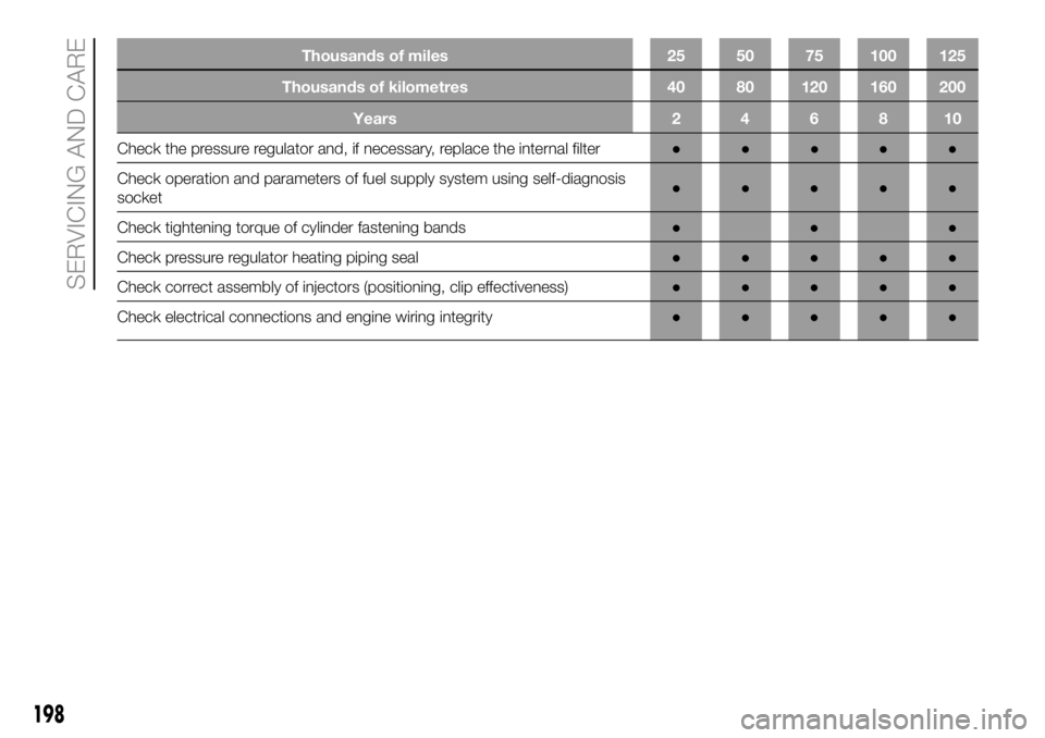
Thousands of miles 25 50 75 100 125
Thousands of kilometres 40 80 120 160 200
Years246810
Check the pressure regulator and, if necessary, replace the internal filter●●●●●
Check operation andparameters of fuel supply system using self-diagnosis
socket●●●●●
Check tightening torque of cylinder fastening bands●●●
Check pressure regulator heating piping seal●●●●●
Check correct assembly of injectors (positioning, clip effectiveness)●●●●●
Check electrical connections and engine wiring integrity●●●●●
198
SERVICING AND CARE
Page 213 of 304
SNOW TYRES
The performance of these tyres is
considerably reduced when the tread
depth is less than 4 mm. Replace them
in this case.
IMPORTANT When using snow tyres
with a maximum speed index below the
one that can be reached by the vehicle
(increased by 5%), place a notice in
the passenger compartment, plainly in
view, which states the maximum speed
allowed by the snow tyres (as per EC
Directive).
All four tyres should be the same (brand
and track) to ensure greater safety
when driving and braking as well as a
good manoeuvrability.
Remember that you should not change
the rotation direction of the tyres.
204)
WARNING
204)The maximum speed for snow tyres
marked “Q” is 160 km/h, while it is 190
km/h for “T” tyres and 210 km/h for "H"
tyres. You should, however, always stick to
the speed limits of the highway code.
SNOW CHAINS
The use of snow chains should be in
compliance with local regulations of
each country.
Snow chains can be fitted to the tyres
of the front wheels (drive wheels) only.
Use of Lineaccessori MOPAR snow
chains is recommended. Check the
tension of the snow chains after the first
few metres have been driven.
58)
IMPORTANT With snow chains, use the
accelerator with extreme care to
prevent, or to limit as much as possible,
slipping of the drive wheels that could
cause chain breakage, resulting in
damage to the car body or mechanical
components.
IMPORTANT For versions fitted with
225/75 R16 tyre, use snow chains with
max. thickness 16 mm.
When travelling on snowy roads with
snow chains, it may be helpful to turn
the ASR off: in fact, in these conditions,
the drive wheels skidding when setting
off gives you better traction.
WARNING
58)Keep the vehicle's speed down when
snow chains are fitted; never exceed 50
km/h. Avoid potholes, do not drive over
steps or pavements, and do not drive long
distances over roads without snow, to
avoid damaging both your vehicle and the
road surface.
211