air condition FIAT DUCATO BASE CAMPER 2018 Owner handbook (in English)
[x] Cancel search | Manufacturer: FIAT, Model Year: 2018, Model line: DUCATO BASE CAMPER, Model: FIAT DUCATO BASE CAMPER 2018Pages: 304, PDF Size: 14.93 MB
Page 40 of 304
HEATING AND
VENTILATION
CONTROLS
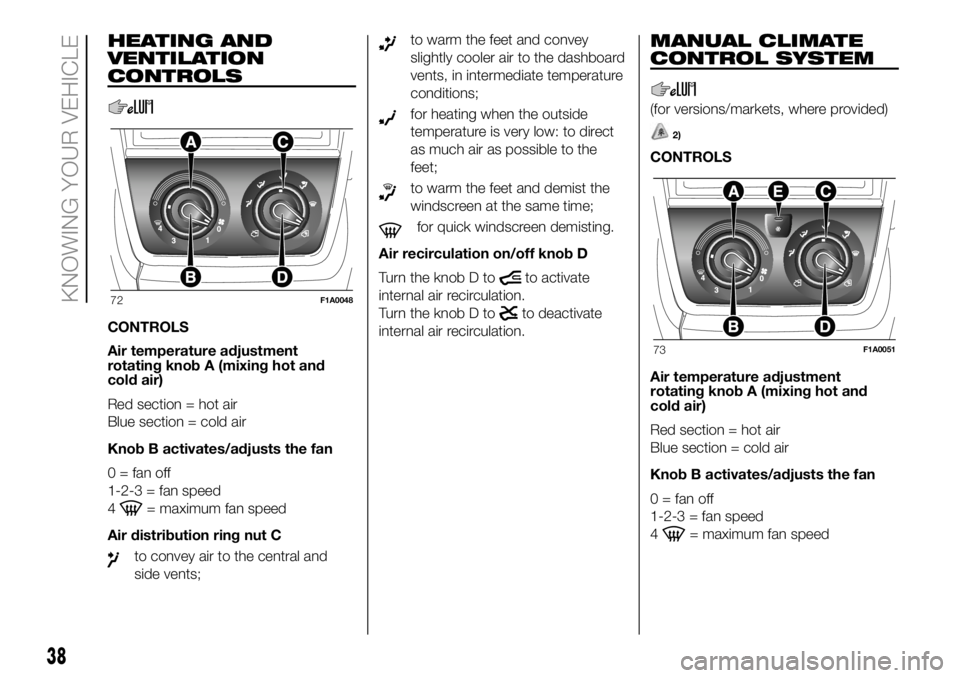
CONTROLS
Air temperature adjustment
rotating knob A (mixing hot and
cold air)
Red section = hot air
Blue section = cold air
Knob B activates/adjusts the fan
0 = fan off
1-2-3 = fan speed
4
= maximum fan speed
Air distribution ring nut C
to convey air to the central and
side vents;
to warm the feet and convey
slightly cooler air to the dashboard
vents, in intermediate temperature
conditions;
for heating when the outside
temperature is very low: to direct
as much air as possible to the
feet;
to warm the feet and demist the
windscreen at the same time;
for quick windscreen demisting.
Air recirculation on/off knob D
Turn the knob D to
to activate
internal air recirculation.
Turn the knob D to
to deactivate
internal air recirculation.
MANUAL CLIMATE
CONTROL SYSTEM
(for versions/markets, where provided)
2)
CONTROLS
Air temperature adjustment
rotating knob A (mixing hot and
cold air)
Red section = hot air
Blue section = cold air
Knob B activates/adjusts the fan
0 = fan off
1-2-3 = fan speed
4
= maximum fan speed
72F1A0048
73F1A0051
38
KNOWING YOUR VEHICLE
Page 41 of 304

Air distribution ring nut C
to convey air to the central and
side vents;
to warm the feet and convey
slightly cooler air to the dashboard
vents, in intermediate temperature
conditions;
for heating when the outside
temperature is very low: to direct
as much air as possible to the
feet;
to warm the feet and demist the
windscreen at the same time;
for quick windscreen demisting.
Air recirculation on/off knob D
Press the button (button LED on) to
turn the internal air recirculation on.
Press the button again (button LED off)
to turn the internal air recirculation off.
Climate control system on/off
button E
Press the button (button LED on) to
turn the climate control system on.
Press the button again (button LED off)
to turn the climate control system off.
AUTOMATIC
CLIMATE CONTROL
SYSTEM
2)
(for versions/markets, where provided)
CONTROLS
AAUTO button automatic control of all
functions.
BAir distribution selection button.
CDisplay.
DMAX DEF function control button.
ESystem off button.
FCompressor enabling/disabling
control button.
GAir recirculation control button.
HFan speed increase/decrease control
buttons.
ITemperature increase/decrease
control knob.USING THE CLIMATE
CONTROL SYSTEM
The system can be started in different
ways, but it is advisable to start by
pressing the AUTO button and then
turning the knob to set the temperature
required on the display.
The system will adjust the temperature,
the quantity and the distribution of the
air sent into the passenger
compartment and, by managing the
recirculation function, the activation of
the climate control system compressor.
During fully automatic operation, the
only manual intervention required is the
possible activation of the following
functions:
air recirculation (to keep the
recirculation constantly on or constantly
off);
to speed up demisting/
defrosting the windscreen, rearscreen
and external rear-view mirrors.
74F1A0054
39
Page 42 of 304
During fully automatic system
operation, you can change the set
temperature, air distribution and fan
speed at any time by using the relevant
buttons or knobs: the system will
automatically change its settings to
adjust to the new requirements. During
fully automatic operation (FULL AUTO),
the word FULL will disappear if the air
distribution and/or flow rate and/or
engagement of the compressor and/or
recirculation settings are changed. In
this way, the functions will switch from
automatic to manual control until the
AUTO button is pressed again.
WARNING
2)The air conditioning system uses R134a
or R1234yf refrigerant compatible with
the regulations in force in the countries
where the vehicle is sold. When charging,
only use the gas indicated on the
dedicated plate in the engine compartment
. The use of other coolants affects the
efficiency and condition of the system. The
lubricant used for the compressor is also
strictly linked to the type of cooling gas,
please refer to a Fiat Dealership.
ADDITIONAL
HEATER
(for versions/markets, where provided)
On some versions, an additional heater
is also present beneath the driver's
seat. The fan for this heater is operated
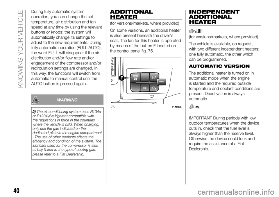
by means of the button F located on
the control panel fig. 75.
INDEPENDENT
ADDITIONAL
HEATER
(for versions/markets, where provided)
The vehicle is available, on request,
with two different independent heaters:
one fully automatic, the other which
can be programmed.
AUTOMATIC VERSION
The additional heater is turned on in
automatic mode when the engine
is started and the required outside
temperature and coolant conditions are
present. Deactivation is always
automatic.
35)
IMPORTANT During periods with low
outdoor temperatures when the device
cuts in, check that the fuel level is
always higher than the reserve level.
Otherwise the device could lock and
require the assistance of a Fiat
Dealership.
MODEF
75F1A0305
40
KNOWING YOUR VEHICLE
Page 46 of 304
Turn the knob D to the maximum
heating position (knob at red
sector);warm air will emerge (with the
engine warmed up), from the rear
footwell outlets (located under the seats
in the 2nd and 3rd row for Panorama
versions and the grille on the left wheel
arch side for Combi versions).
ADDITIONAL REAR
CLIMATE CONTROL
(Panorama and Combi)
(for versions/markets, where provided)
The Panorama and Combi versions
are equipped with a main heating/air
conditioning system plus an additional
system (available on request) with
controls in the roof panel trim above the
second row of seats fig. 77. Button F
fig. 78 on the control panel must be
enabled for operation; the air
conditioning only works if the main
climate control system is on.
When the knob D is placed in the
fully cold position (control in blue sector)
cold air comes out the vents in the
ceiling.
Turn the knob D to the maximum
heating position (knob at red
sector);warm air will emerge (with the
engine warmed up), from the rear
footwell outlets (located under the seats
in the 2nd and 3rd row for Panorama
versions and the grille on the left wheel
arch side for Combi versions).
If the selector knob D is placed in
the intermediate positions, the air
will be distributed between the vents in
the ceiling and the rear footwell vents,
varying the temperature.
IMPORTANT If the compressor on the
main climate control system control
is turned on (operation of button E),
even if the additional climate control
system fan is in position 0, the 1st
speed will automatically be activated to
prevent ice formation, with possible
damage to the component.
WARNING
35)The heater burns fuel in the same way
as the engine, though to a lesser extent. To
prevent poisoning and asphyxiation, the
supplementary heater must never be
turned on, not even for short periods, in
closed environments such as a garage or
workshops without extraction fans for
the exhaust gases.
ELECTRIC WINDOWS
ELECTRIC
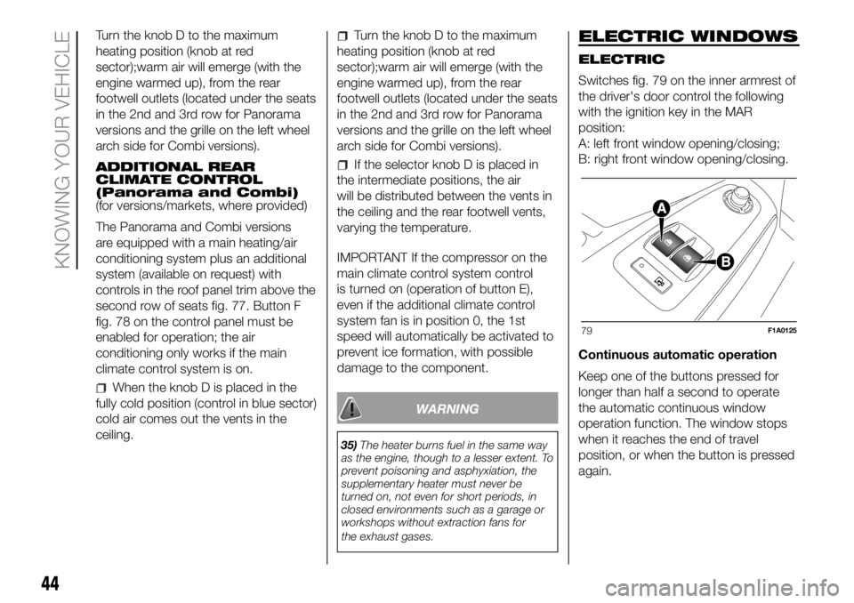
Switches fig. 79 on the inner armrest of
the driver's door control the following
with the ignition key in the MAR
position:
A: left front window opening/closing;
B: right front window opening/closing.
Continuous automatic operation
Keep one of the buttons pressed for
longer than half a second to operate
the automatic continuous window
operation function. The window stops
when it reaches the end of travel
position, or when the button is pressed
again.
79F1A0125
44
KNOWING YOUR VEHICLE
Page 51 of 304
The tachograph is installed and sealed
by authorised personnel: do not try
and access the device or the supply
and recording leads in any way. It is the
responsibility of the owner of the vehicle
on which the tachograph is installed to
check the device regularly.
The check must be carried out at least
every two years and a test must be
carried out to ensure that it is working
properly. Ensure that the data label
is renewed after every check and that
the label contains the specified data.SELF-LEVELLING AIR
SUSPENSION
GENERAL INFORMATION
The system only acts on the rear
wheels.
The system maintains the rear ride
setting for the vehicle constant in any
loading condition, while ensuring a
greater driving comfort.
HEIGHT ADJUSTMENT
There are 7 pre-defined levels for the
free height from the ground: from “ride
-3” to “ride 0” till “ride +3”.
The trim is shown on the multifunction
display
Automatic adjustment
When moving, the system automatically
shows that the vehicle is in 'ride setting
0' and keeps it constant.
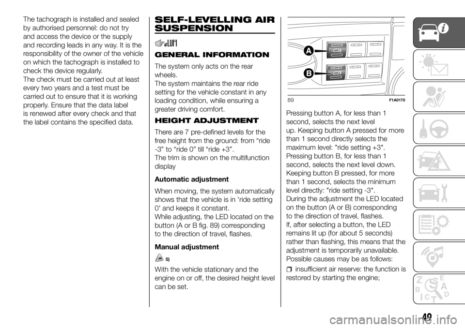
While adjusting, the LED located on the
button (A or B fig. 89) corresponding
to the direction of travel, flashes.
Manual adjustment
5)
With the vehicle stationary and the
engine on or off, the desired height level
can be set.Pressing button A, for less than 1
second, selects the next level
up. Keeping button A pressed for more
than 1 second directly selects the
maximum level: "ride setting +3".
Pressing button B, for less than 1
second, selects the next level down.
Keeping button B pressed, for more
than 1 second, selects the minimum
level directly: "ride setting -3".
During the adjustment the LED located
on the button (A or B) corresponding
to the direction of travel, flashes.
If, after selecting a button, the LED
remains lit up (for about 5 seconds)
rather than flashing, this means that the
adjustment is temporarily unavailable.
Possible causes may be as follows:insufficient air reserve: the function is
restored by starting the engine;
89F1A0170
49
Page 95 of 304
DRIVING ADVISOR
(lane crossing warning)
(for versions/markets, where provided)
78) 79) 80)
The Driving Advisor is a warning system
that notifies the driver if he/she crosses
the lane because he/she has been
distracted.
A video sensor, fitted on the windscreen
near the interior rear view mirror,
detects the lane demarcation lines and
the position of the vehicle in relation
to them.
IMPORTANT On cars with Driving
Advisor, it is advisable to contact a Fiat
Dealership should the windscreen
need to be replaced. If the repair is
carried out at a specialist window
replacement centre, it is still necessary
to go to a Fiat Dealership to have the
camera calibrated.
OPERATION
The system is always active when the
vehicle is started. It can be deactivated
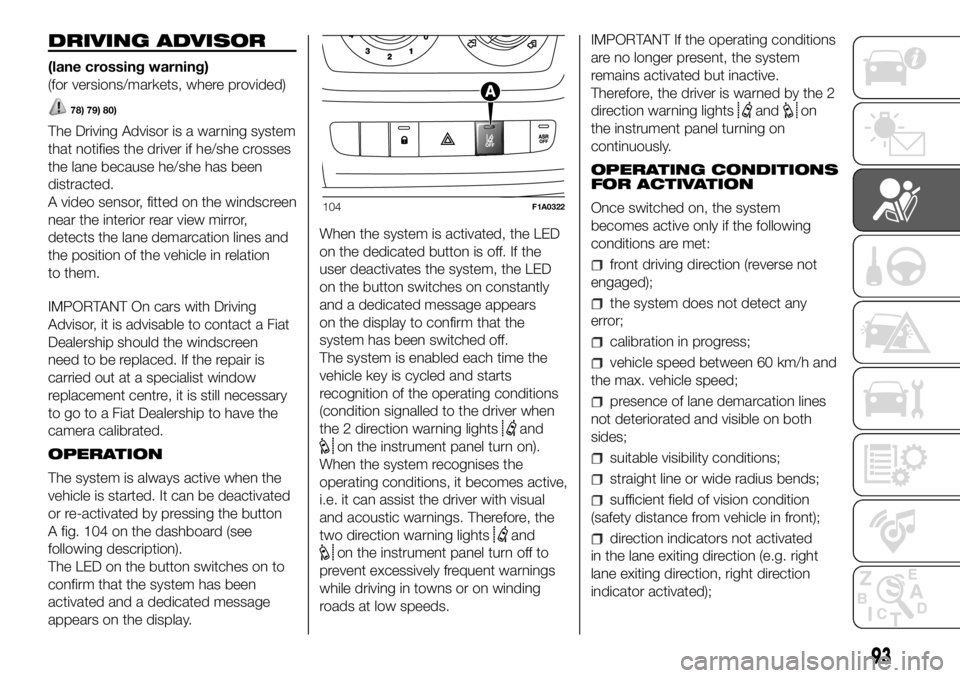
or re-activated by pressing the button
A fig. 104 on the dashboard (see
following description).
The LED on the button switches on to
confirm that the system has been
activated and a dedicated message
appears on the display.When the system is activated, the LED
on the dedicated button is off. If the
user deactivates the system, the LED
on the button switches on constantly
and a dedicated message appears
on the display to confirm that the
system has been switched off.
The system is enabled each time the
vehicle key is cycled and starts
recognition of the operating conditions
(condition signalled to the driver when
the 2 direction warning lights
and
on the instrument panel turn on).
When the system recognises the
operating conditions, it becomes active,
i.e. it can assist the driver with visual
and acoustic warnings. Therefore, the
two direction warning lights
and
on the instrument panel turn off to
prevent excessively frequent warnings
while driving in towns or on winding
roads at low speeds.IMPORTANT If the operating conditions
are no longer present, the system
remains activated but inactive.
Therefore, the driver is warned by the 2
direction warning lights
andon
the instrument panel turning on
continuously.
OPERATING CONDITIONS
FOR ACTIVATION
Once switched on, the system
becomes active only if the following
conditions are met:
front driving direction (reverse not
engaged);
the system does not detect any
error;
calibration in progress;
vehicle speed between 60 km/h and
the max. vehicle speed;
presence of lane demarcation lines
not deteriorated and visible on both
sides;
suitable visibility conditions;
straight line or wide radius bends;
sufficient field of vision condition
(safety distance from vehicle in front);
direction indicators not activated
in the lane exiting direction (e.g. right
lane exiting direction, right direction
indicator activated);
104F1A0322
93
Page 113 of 304
SUPPLEMENTARY
RESTRAINT SYSTEM
(SRS) - AIRBAG
The vehicle may be equipped with:
driver front airbag;
passenger front airbag;
front side bags to protect the pelvis
and chest of the driver and passenger;
window bags to protect the heads
of the front seat occupants.
The airbag locations on the vehicle are
marked by the word "AIRBAG" in the
middle of the steering wheel, on the
dashboard, on the side lining or on
a label placed next to the airbag
deployment area.
FRONT AIRBAGS
The front airbags protect the front seat
occupants in the event of a medium-
high severity frontal impact, by placing
the bag between the occupant and
the steering wheel or dashboard.
Therefore, non-activation in other types
of collisions (side collisions, rear shunts,
roll-overs, etc.) is not a system
malfunction.
An electronic control unit will make the
bag inflate in the event of a frontal
impact.The bag will inflate instantaneously
placing itself between the front
occupants body and the structures
which could cause injury. It will deflate
immediately afterwards.
Front airbags are not a replacement of
but complementary to the seat belts,
which you are recommended to always
wear, as specified by law in Europe
and most non-European countries.
In the event of an impact, someone not
wearing a seat belt could move forward
and come into contact with a bag
which is still opening. The protection
offered by the bag is compromised
in these circumstances.
Front airbags may not activate in the
following situations:
frontal impacts against highly
deformable objects not involving the
front surface of the vehicle (e.g. wing
collision against guard rail, etc.);
when the vehicle is wedged under
other vehicles or protective barriers
(e.g. under a lorry or a guardrail); Failure
to deploy in the conditions described
above is due to the fact that the airbags
may not provide any additional
protection compared with seat belts, so
their activation would be inappropriate.
In these cases, non-deployment does
not indicate a system malfunction.
100)
The driver's and passenger's front
airbags have been designed and
calibrated to protect front seat
occupants wearing seat belts. At their
maximum inflation, their volume fills
most of the space between the steering
wheel and the driver and between the
dashboard and the passenger.
The airbags are not deployed in the
event of minor frontal impacts (for
which the restraining action of the seat
belts is sufficient). Seat belts must
always be worn. In the event of a frontal
collision, they ensure the correct
positioning of the occupant.
FRONT AIRBAG DRIVER'S
SIDE
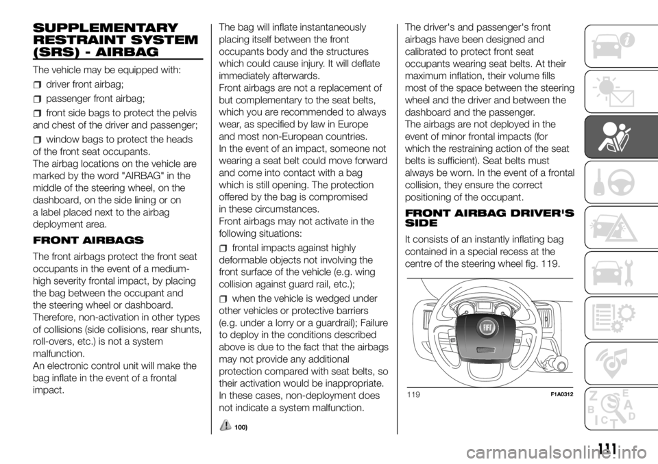
It consists of an instantly inflating bag
contained in a special recess at the
centre of the steering wheel fig. 119.
119F1A0312
111
Page 133 of 304
TRAFFIC SIGN
RECOGNITION
(for versions/markets, where provided)
125) 126) 127) 128)
28) 29) 30) 31) 32) 33) 34)
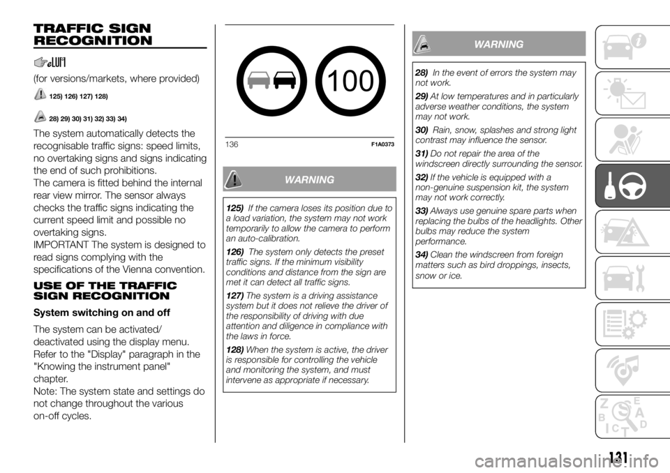
The system automatically detects the
recognisable traffic signs: speed limits,
no overtaking signs and signs indicating
the end of such prohibitions.
The camera is fitted behind the internal
rear view mirror. The sensor always
checks the traffic signs indicating the
current speed limit and possible no
overtaking signs.
IMPORTANT The system is designed to
read signs complying with the
specifications of the Vienna convention.
USE OF THE TRAFFIC
SIGN RECOGNITION
System switching on and off
The system can be activated/
deactivated using the display menu.
Refer to the "Display" paragraph in the
"Knowing the instrument panel"
chapter.
Note: The system state and settings do
not change throughout the various
on-off cycles.
WARNING
125)If the camera loses its position due to
a load variation, the system may not work
temporarily to allow the camera to perform
an auto-calibration.
126)The system only detects the preset
traffic signs. If the minimum visibility
conditions and distance from the sign are
met it can detect all traffic signs.
127)The system is a driving assistance
system but it does not relieve the driver of
the responsibility of driving with due
attention and diligence in compliance with
the laws in force.
128)When the system is active, the driver
is responsible for controlling the vehicle
and monitoring the system, and must
intervene as appropriate if necessary.
WARNING
28)In the event of errors the system may
not work.
29)At low temperatures and in particularly
adverse weather conditions, the system
may not work.
30)Rain, snow, splashes and strong light
contrast may influence the sensor.
31)Do not repair the area of the
windscreen directly surrounding the sensor.
32)If the vehicle is equipped with a
non-genuine suspension kit, the system
may not work correctly.
33)Always use genuine spare parts when
replacing the bulbs of the headlights. Other
bulbs may reduce the system
performance.
34)Clean the windscreen from foreign
matters such as bird droppings, insects,
snow or ice.
100
136F1A0373
131
Page 148 of 304

Please note that the tow bar can be
installed only when in these conditions.
If the locking mechanism of the tow
bar is disengaged before the
installation, or at any other time, and is
in the locked position, it must be
pre-loaded. The locked position can be
identified by the green mark of the
flywheel coinciding with the green mark
of the tow bar and by the flywheel in
the stop position on the tow bar,
namely without slot (see figure).
The locking mechanism is pre-loaded
as follows: with the key inserted and
the lock open, extract the flywheel
following the direction of the arrow and,
to pre-load, rotate according to the
direction of the arrow b until the stop.
The release lever is engaged and the
locking mechanism remains in the
pre-loading position even when the
flywheel is released. The tow bar must
be inserted in the housing pipe with the
coupling pin for the installation. Insert
from the bottom and push upwards.
The mechanism then locks
automatically. Keep your hands far from
the flywheel, as it rotates during the
locking procedure.2. The tow bar must be inserted in the
housing pipe with the coupling pin
for the installation. Insert from the
bottom and push upwards. The
mechanism then locks automatically.
Keep your hands far from the flywheel,
as it rotates during the locking
procedure.
3. Close the lock and always remove
the key. The key cannot be removed
when the lock is released. Apply the
protection cap on the lock.
Removing the tow bar
1. Remove the protection cap from the
lock and press it on the key grip. Open
the lock with the key.
2. Hold the tow bar firmly, remove the
flywheel following the direction of the
arrow and rotate according to the
direction of the arrow b until stopping,
so as to remove till the extracted
position. Then remove the tow bar from
the housing pipe. The flywheel can
then be released; it autonomously
stops in the released position.
3. Arrange the tow bar in the luggage
compartment so that it cannot be
dirtied or damaged by other
transported objects.
4. Insert the suitable plug in the
mounting pipe.
WARNING
41)The removable ball head bar must be
repaired and taken apart by the
manufacturer only.
42)The accompanying plate must be in a
highly visible point of the vehicle, near
the mounting pipe or inside the luggage
compartment.
43)To ensure correct operation of the
system, periodically remove all dirt deposits
from the ball head bar and from the
mounting pipe. The mechanical
components must be serviced at the
specified intervals. The lock must only be
treated with graphite.
44)Periodically lubricate the joints, the
sliding surfaces and the balls with grease
without resin or oil. Lubrication is also a
further corrosion protection.
45)If the vehicle is washed with high-
pressure jets, the ball head bar must be
removed and the dedicated cap fitted. The
ball head bar must never be treated with
steam jets.
46)Two keys are supplied together with
the removable ball tow bar. Note down the
key number on the pawl for any following
order and keep it.
146
STARTING AND DRIVING
Page 165 of 304
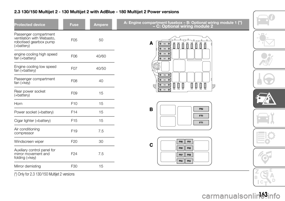
2.3 130/150 Multijet 2 - 130 Multijet 2 with AdBlue - 180 Multijet 2 Power versions
Protected device Fuse AmpereA: Engine compartment fusebox – B: Optional wiring module 1(*)
– C: Optional wiring module 2
Passenger compartment
ventilation with Webasto,
robotised gearbox pump
(+battery)F05 50
engine cooling high speed
fan (+battery)F06 40/60
Engine cooling low speed
fan (+battery)F07 40/50
Passenger compartment
fan (+key)F08 40
Rear power socket
(+battery)F09 15
Horn F10 15
Power socket (+battery) F14 15
Cigar lighter (+battery) F15 15
Air conditioning
compressorF19 7.5
Windscreen wiper F20 30
Auxiliary control panel for
mirror movement and
folding (+key)F24 7.5
Mirror demisting F30 15
(*) Only for 2.3 130/150 Multijet 2 versions
163