sensor FIAT DUCATO BASE CAMPER 2018 Owner handbook (in English)
[x] Cancel search | Manufacturer: FIAT, Model Year: 2018, Model line: DUCATO BASE CAMPER, Model: FIAT DUCATO BASE CAMPER 2018Pages: 304, PDF Size: 14.93 MB
Page 18 of 304
MOVING FOOTBOARD
(for versions/markets, where provided)
On opening the passenger
compartment side door or the luggage
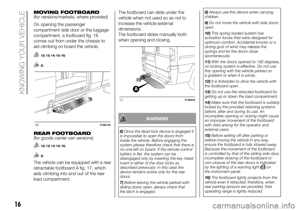
compartment, a footboard fig. 16
comes out from under the chassis to
aid climbing on board the vehicle.
12) 13) 14) 15) 16)
2)
REAR FOOTBOARD
(for goods carrier van versions)
12) 13) 14) 15) 16)
2)
The vehicle can be equipped with a rear
retractable footboard A fig. 17, which
aids climbing into and out of the rear
load compartment.The footboard can slide under the
vehicle when not used so as not to
increase the vehicle external
dimensions.
The footboard slides manually both
when opening and closing.
WARNING
6)Once the dead lock device is engaged it
is impossible to open the doors from
inside the vehicle. Before engaging the
system please therefore check that there is
no-one left on board. If the remote control
battery is flat, the system can be
disengaged only by inserting the key metal
insert in either of the door locks as
described previously: in this case the
device remains active only for the rear
doors.
7)Before leaving the vehicle parked with
sliding doors open, always check that
the latch is engaged.8)Always use this device when carrying
children.
9)Do not move the vehicle with side doors
open.
10)This spring loaded system has
activation forces that were designed for
optimum comfort. Accidental knocks or a
strong gust of wind may release the
springs and let the doors close
spontaneously.
11)With the doors opened to 180 degrees,
no locking system is effective. Do not use
this opening with the vehicle parked on
a gradient or when it is windy.
12)It is forbidden to drive the vehicle with
the footboard open.
13)Do not use the retracted footboard for
getting up or down the load compartment.
14)Make sure that the footboard is suitably
locked by the provided retaining systems
before, after and during its use. An
incomplete opening or closing might cause
an improper movement of the footboard
with risks arising for the operator and
external users.
15)Before setting off after parking or
before moving the vehicle in any way,
ensure the footboard is fully stowed away.
Because the movement of the footboard
is controlled by that of the sliding side door,
incomplete stowing of the footboard or
non-closure of the rear doors is indicated
by the lighting of a warning light
on
the instrument panel.
16)The footboard lightly projects from the
vehicle even if retracted; therefore, when
rear parking sensors are provided, their
operating range is lightly reduced.
16F1A0119
17F1A0410
16
KNOWING YOUR VEHICLE
Page 31 of 304
PARKING LIGHTS
These lights can only be turned on with
ignition key in the STOP position or
removed, by moving the left stalk ring
first to theOposition and then to the
orposition.
The
warning light switches on in
the instrument panel.
DIRECTION INDICATORS
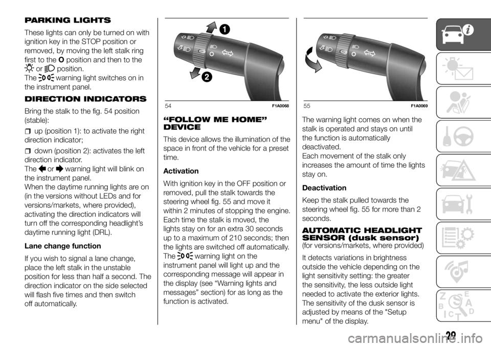
Bring the stalk to the fig. 54 position
(stable):
up (position 1): to activate the right
direction indicator;
down (position 2): activates the left
direction indicator.
The
orwarning light will blink on
the instrument panel.
When the daytime running lights are on
(in the versions without LEDs and for
versions/markets, where provided),
activating the direction indicators will
turn off the corresponding headlight’s
daytime running light (DRL).
Lane change function
If you wish to signal a lane change,
place the left stalk in the unstable
position for less than half a second. The
direction indicator on the side selected
will flash five times and then switch
off automatically.“FOLLOW ME HOME”
DEVICE
This device allows the illumination of the
space in front of the vehicle for a preset
time.
Activation
With ignition key in the OFF position or
removed, pull the stalk towards the
steering wheel fig. 55 and move it
within 2 minutes of stopping the engine.
Each time the stalk is moved, the
lights stay on for an extra 30 seconds
up to a maximum of 210 seconds; then
the lights are switched off automatically.
The
warning light on the
instrument panel will light up and the
corresponding message will appear in
the display (see “Warning lights and
messages” section) for as long as the
function is activated.The warning light comes on when the
stalk is operated and stays on until
the function is automatically
deactivated.
Each movement of the stalk only
increases the amount of time the lights
stay on.
Deactivation
Keep the stalk pulled towards the
steering wheel fig. 55 for more than 2
seconds.
AUTOMATIC HEADLIGHT
SENSOR (dusk sensor)
(for versions/markets, where provided)
It detects variations in brightness
outside the vehicle depending on the
light sensitivity setting: the greater
the sensitivity, the less outside light
needed to activate the exterior lights.
The sensitivity of the dusk sensor is
adjusted by means of the "Setup
menu" of the display.
54F1A006855F1A0069
29
Page 32 of 304
Activation
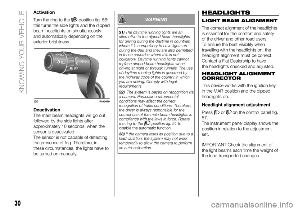
Turn the ring to the
position fig. 56:
this turns the side lights and the dipped
beam headlights on simultaneously
and automatically depending on the
exterior brightness.
Deactivation
The main beam headlights will go out
followed by the side lights after
approximately 10 seconds, when the
sensor is deactivated.
The sensor is not capable of detecting
the presence of fog. Therefore, in
these circumstances, the lights have to
be turned on manually.WARNING
31)The daytime running lights are an
alternative to the dipped beam headlights
for driving during the daytime in countries
where it is compulsory to have lights on
during the day, and they are also permitted
in those countries where this is not
obligatory. Daytime running lights cannot
replace dipped beam headlights when
driving at night or through tunnels. The use
of daytime running lights is governed by
the highway code of the country in which
you are driving. Comply with legal
requirements.
32)The system is based on recognition via
a camera. Particular environmental
conditions may affect the correct
recognition of traffic conditions. Therefore,
the driver is always responsible for the
correct use of the main beam headlights in
compliance with the laws in force. Rotate
the ring to the
position fig. 51to
disable the automatic function.
33)If the camera loses its position due to a
load variation, the system may not work
temporarily to allow the camera to perform
an auto-calibration.
HEADLIGHTS
LIGHT BEAM ALIGNMENT
The correct alignment of the headlights
is essential for the comfort and safety
of the driver and other road users.
To ensure the best visibility when
travelling with the headlights on, the
headlight alignment must be correct.
Contact a Fiat Dealership to have
the headlights checked and adjusted.
HEADLIGHT ALIGNMENT
CORRECTOR
This device works with the ignition key
in the MAR position and the dipped
headlights on.
Headlight alignment adjustment
Press
oron the control panel fig.
57.
The instrument panel display shows the
position in relation to the adjustment
set.
IMPORTANT Check the alignment of
the light beams each time the weight of
the load transported changes.
56F1A0070
30
KNOWING YOUR VEHICLE
Page 36 of 304
With the battery disconnected, access
to the vehicle will only be possible by
unlocking the driver's door using the
mechanical lock.
To restore the battery connection, insert
the ignition key and turn it to the MAR
position, the vehicle can be started
normally at this point.
If the battery is disconnected, it may be
necessary to set certain electrical
devices again (e.g. clock, date, etc.).
DOOR LOCKING
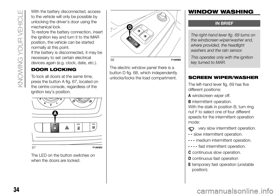
To lock all doors at the same time,
press the button A fig. 67, located on
the centre console, regardless of the
ignition key's position.
The LED on the button switches on
when the doors are locked.The electric window panel there is a
button D fig. 68, which independently
unlocks/locks the load compartment.WINDOW WASHING
IN BRIEF
The right-hand lever fig. 69 turns on
the windscreen wiper/washerand,
where provided, the headlight
washers and the rain sensor.
This operates only with the ignition
key turned to MAR.
SCREEN WIPER/WASHER
The left-hand lever fig. 69 has five
different positions:
Awindscreen wiper off.
Bintermittent operation.
With the stalk in position B, turn ring
nut F to select one of four different
speeds for the intermittent operation
mode:
very slow intermittent operation.
--slow intermittent operation.
---medium intermittent operation.
----fast intermittent operation.
Ccontinuous slow operation.
Dcontinuous fast operation
Etemporary fast operation (unstable
position).
67F1A0303
68F1A0085
34
KNOWING YOUR VEHICLE
Page 37 of 304

Temporary fast operation in position E
is limited to the time that the lever is
manually held in this position. The lever
returns to position A when it is
released, automatically stopping the
windscreen wipers.
4)
IMPORTANT We recommend replacing
the blades once a year.“Smart washing” function
Pulling the stalk towards the steering
wheel (unstable position) operates
the windscreen washer fig. 70.
Keeping the stalk pulled for more than
half a second, with just one movement
it is possible to operate the washer
jet and the wiper at the same time.
The windscreen wiper stops working
three strokes after the stalk is released.
A further stroke after approx. 6 seconds
completes the wiping cycle.
RAIN SENSOR
(for versions/markets, where provided)
The rain sensor is located behind the
driving mirror in contact with the
windscreen and has the purpose of
automatically adjust, during the
intermittent operation, the frequency of
the windscreen wiper strokes as to
the rain intensity.IMPORTANT Keep the glass in the
sensor area clean.
Activation fig. 69
Move the right lever down by one click
(position B).
The activation of the sensor is signalled
by a "stroke" to show that the
command has been acquired.
Turn the control F to increase the rain
sensor sensitivity.
The increasing of the rain sensor
sensitivity is signalled by a "stroke" to
show that the command has been
acquired.
If the windscreen washer is used with
the rain sensor activated, the normal
washing cycle is performed, after which
the rain sensor resumes its normal
automatic operation.
Deactivation fig. 69
Move the lever from position B or turn
the ignition key to OFF. The next time
the vehicle is started (ignition key in ON
position), the sensor is not reactivated
even if the lever is still in position B.
To activate the sensor, move the lever
to position A or C and then back to
position B or turn the ring nut for
adjusting the sensitivity. Rain sensor
activation will be indicated by at least
one wiper “stroke” even if the
windscreen is dry.
69F1A0071
70F1A0072
35
Page 38 of 304
The rain sensor is capable of
recognising the difference between day
and night and making the necessary
adjustments automatically.
34)
HEADLIGHT WASHERS
(for versions/markets, where provided)
The headlight washers are “retractable”,
i.e.: they are located inside the front
bumper and they are activated when
(with dipped beams on) the windscreen
washer is operated.
IMPORTANT Check the correct
condition and cleanliness of nozzles at
regular intervals.
WARNING
34)Streaks of water may cause
unnecessary blade movements.
WARNING
4)Never use the windscreen wiper to
remove layers of snow or ice from
the windscreen. In such conditions, the
windscreen wiper may be subjected to
excessive stress and the motor cut-out
switch, which prevents operation for a few
seconds, may intervene. If operation is
not restored, contact a Fiat Dealership.
36
KNOWING YOUR VEHICLE
Page 53 of 304
KNOWING THE INSTRUMENT PANEL
This section of the booklet gives you all
the information you need to
understand, interpret and use the
instrument panel correctly.CONTROL PANEL AND
ON-BOARD INSTRUMENTS ........... 52
DISPLAY ........................................ 56
TRIP COMPUTER ........................... 58
WARNING LIGHTS AND
MESSAGES .................................... 60
-LOW BRAKE FLUID/HANDBRAKE
ENGAGED........................................... 60
-EBD FAILURE .................................... 61
-AIR BAG FAILURE .............................. 61
-SEAT BELTS REMINDER.................... 62
-ENGINE COOLANT TEMPERATURE
TOO HIGH........................................... 63
-LOW BATTERY CHARGE ................... 63
-LOW ENGINE OIL PRESSURE ........... 64
-ENGINE OIL DETERIORATED ............ 64
-INCOMPLETE DOOR/LOAD
COMPARTMENT CLOSURE................ 65
-POWER STEERING FAILURE ............. 65
-SELF-LEVELLING SUSPENSION
FAILURE .............................................. 65
-INJECTION/EOBD SYSTEM
FAILURE .............................................. 67
-UREA INJECTION SYSTEM FAILURE. 68
-ABS FAILURE..................................... 68
-FUEL RESERVE ................................. 68
-GLOW PLUG PREHEATING / GLOW
PLUG PREHEATING FAILURE ............. 69
-LOW DIESEL EMISSIONS ADDITIVE
(UREA) LEVEL WARNING .................... 69
-VEHICLE PROTECTION SYSTEM
FAILURE - FIAT CODE ......................... 70
-REAR FOG LIGHTS............................ 70
-GENERAL FAILURE INDICATION ....... 71
-DPF (PARTICULATE FILTER)
CLEANING UNDERWAY ...................... 72
-BRAKE PAD WEAR ............................ 72
-DRIVING ADVISOR ............................ 73-TPMS SYSTEM .................................. 74
-DIPPED BEAM HEADLIGHTS ............ 75
-FOLLOW ME HOME .......................... 75
-LEFT DIRECTION INDICATOR ............ 75
-RIGHT DIRECTION INDICATOR ......... 75
-FOG LIGHTS ...................................... 75
-CRUISE CONTROL ............................ 76
-SPEED LIMITER ................................. 76
-AUTOMATIC MAIN BEAM
HEADLIGHTS ...................................... 76
-MAIN BEAM HEADLIGHTS ................ 76
-"UP" FUNCTION ................................ 77
-EXTERIOR LIGHTS FAILURE .............. 78
-LOW ENGINE OIL PRESSURE
WARNING LIGHT FAILURE ................. 78
-BRAKE LIGHT FAILURE ..................... 78
-MAIN BEAM AUTOMATISM FAULT .... 78
-POSSIBLE ICE ON ROAD .................. 79
-SPEED LIMIT EXCEEDED .................. 79
-SCHEDULED SERVICING .................. 79
-FUEL CUT-OFF DEVICE INERTIA
SWITCH TRIPPED ............................... 80
-COMFORT-MATIC SYSTEM FAILURE
INDICATION ........................................ 80
-PARKING SENSOR FAILURE ............. 80
-DRIVING ADVISOR SYSTEM
FAILURE .............................................. 80
-TRAFFIC SIGN RECOGNITION
FAILURE .............................................. 80
-LIMITED RANGE ................................ 80
-START&STOP SYSTEM
ACTIVATION/DEACTIVATION............... 81
-START&STOP FAILURE ..................... 81
-LOW DIESEL EMISSIONS ADDITIVE
(UREA) LEVEL WARNING .................... 82
-WATER IN DIESEL FILTER (Diesel
versions) .............................................. 82
51
Page 60 of 304
NOTE Theandbuttons
turn on various functions depending on
the situation, as follows:
Adjusting the vehicle interior
lighting
- with the side lights on and standard
screen active, it is possible to adjust the
brightness inside the vehicle.
Setup menu
- within the menu, they allow you to
scroll up and down;
- during setting operations they allow
an increase or decrease.
SETUP MENU
Setup menu functions
The setup menu can be activated by
pressing the MODE button briefly.
The menu comprises the following
functions:
Menu
On
Headlight alignment corrector
Speed warning
Headlight sensor
Cornering lights
Rain sensor
Trip B activation
Traffic sign
Set time
Set date
Autoclose
Units
Language
Warning volume
Service
Passenger's airbag
Daytime running lights
Automatic main beam headlights
Exit menu
Press the
orbuttons to
navigate within the menu
buttons
once to scroll through the setup menu
list.
Operating modes are different
according to the characteristics of the
option selected.
TRIP COMPUTER
IN BRIEF
The Trip computer is used to display
information on vehicleoperation
when the ignition key is turned to
MAR. This function allows you to
define two separate trips, called "Trip
A" and "Trip B", for monitoring the
"complete mission" (journey) of
the vehicle in a reciprocally
independent manner. Both functions
can be reset (reset means start of
a new journey).
"Trip A" can be used to display the
values relating to:
Outside Temperature
Range
Distance travelled A
Average consumption A
Instant consumption
Average speed A
Trip time A (driving time)
Reset Trip A
"Trip B", available on multifunction
display only, is used to display
the values relating to:
58
KNOWING THE INSTRUMENT PANEL
Page 73 of 304
What it means What to do
amberGENERAL FAILURE INDICATION
(Versions with multifunction display)
The warning light turns on in the following
circumstances:
If the fuel inertia cut-off switch is activated
Light failure (rear fog lamps, direction indicators,
brake lights, number plate lights, side lights, daytime
running lights, main beam automatism, trailer direction
indicators, trailer side lights)The failure relating to these lights could be: one or
more blown bulbs, a blown protection fuse or a break
in the electrical connection.
Airbag warning light failure (generic failure warning
light flashing)In this case, the warning light may not indicate
problems with the restraint systems. Before
continuing, contact a Fiat Dealership to have the
system checked immediately.
Rain sensor failure
Diesel filter sensor failure
Trailer connection failure
Audio system failure
Engine oil pressure sensor failure
Parking sensor failure
Water in diesel fuel filterContact a Fiat Dealership as soon as possible to have
the fault fixed.
FOR VERSIONS WITH A MULTIFUNCTION DISPLAY,
THE WARNING LIGHT ALSO TURNS ON IN THE
FOLLOWING CIRCUMSTANCES:
Engine oil level sensor failure
Insufficient engine oil level
71
Page 82 of 304
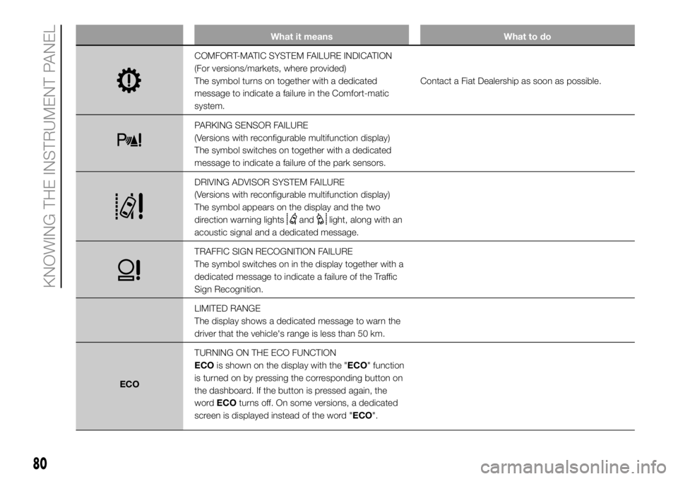
What it means What to do
COMFORT-MATIC SYSTEM FAILURE INDICATION
(For versions/markets, where provided)
The symbol turns on together with a dedicated
message to indicate a failure in the Comfort-matic
system.Contact a Fiat Dealership as soon as possible.
PARKING SENSOR FAILURE
(Versions with reconfigurable multifunction display)
The symbol switches on together with a dedicated
message to indicate a failure of the park sensors.
DRIVING ADVISOR SYSTEM FAILURE
(Versions with reconfigurable multifunction display)
The symbol appears on the display and the two
direction warning lights
andlight, along with an
acoustic signal and a dedicated message.
TRAFFIC SIGN RECOGNITION FAILURE
The symbol switches on in the display together with a
dedicated message to indicate a failure of the Traffic
Sign Recognition.
LIMITED RANGE
The display shows a dedicated message to warn the
driver that the vehicle's range is less than 50 km.
ECOTURNING ON THE ECO FUNCTION
ECOis shown on the display with the "ECO" function
is turned on by pressing the corresponding button on
the dashboard. If the button is pressed again, the
wordECOturns off. On some versions, a dedicated
screen is displayed instead of the word "ECO".
80
KNOWING THE INSTRUMENT PANEL