ignition FIAT FIORINO 2008 Owner handbook (in English)
[x] Cancel search | Manufacturer: FIAT, Model Year: 2008, Model line: FIORINO, Model: FIAT FIORINO 2008Pages: 210, PDF Size: 3.51 MB
Page 120 of 210
119
SAFETY
IN AN
EMERGENCY
MAINTENANCE
AND CARE
TECHNICAL
SPECIFICATIONS
INDEX
DASHBOARDAND CONTROLS
STARTING
AND DRIVING
WARNING
LIGHTS AND
MESSAGES
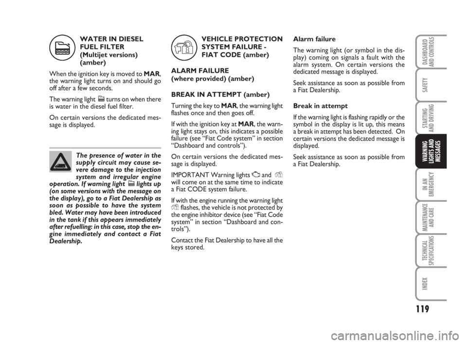
WATER IN DIESEL
FUEL FILTER
(Multijet versions)
(amber)
When the ignition key is moved to MAR,
the warning light turns on and should go
off after a few seconds.
The warning light cturns on when there
is water in the diesel fuel filter.
On certain versions the dedicated mes-
sage is displayed.VEHICLE PROTECTION
SYSTEM FAILURE -
FIAT CODE (amber)
ALARM FAILURE
(where provided) (amber)
BREAK IN ATTEMPT (amber)
Turning the key to MAR, the warning light
flashes once and then goes off.
If with the ignition key at MAR, the warn-
ing light stays on, this indicates a possible
failure (see “Fiat Code system” in section
“Dashboard and controls”).
On certain versions the dedicated mes-
sage is displayed.
IMPORTANT Warning lights Uand Y
will come on at the same time to indicate
a Fiat CODE system failure.
If with the engine running the warning light
Yflashes, the vehicle is not protected by
the engine inhibitor device (see “Fiat Code
system” in section “Dashboard and con-
trols”).
Contact the Fiat Dealership to have all the
keys stored. The presence of water in the
supply circuit may cause se-
vere damage to the injection
system and irregular engine
operation. If warning light clights up
(on some versions with the message on
the display), go to a Fiat Dealership as
soon as possible to have the system
bled. Water may have been introduced
in the tank if this appears immediately
after refuelling: in this case, stop the en-
gine immediately and contact a Fiat
Dealership.
cY
Alarm failure
The warning light (or symbol in the dis-
play) coming on signals a fault with the
alarm system. On certain versions the
dedicated message is displayed.
Seek assistance as soon as possible from
a Fiat Dealership.
Break in attempt
If the warning light is flashing rapidly or the
symbol in the display is lit up, this means
a break in attempt has been detected. On
certain versions the dedicated message is
displayed.
Seek assistance as soon as possible from
a Fiat Dealership.
111-122 Fiorino GB 2ed 8-02-2008 15:08 Pagina 119
Page 146 of 210
145
SAFETY
MAINTENANCE
AND CARE
TECHNICAL
SPECIFICATIONS
INDEX
DASHBOARDAND CONTROLS
STARTING
AND DRIVING
WARNING
LIGHTS AND
MESSAGES
IN AN
EMERGENCY
IF A FUSE BLOWS
GENERAL
Fuses are protective devices for the elec-
tric system: they come into action (i.e. cut
off) mainly due to a fault or improper ac-
tion on the system.
When a specific device does not work cor-
rectly, check the efficiency of the corre-
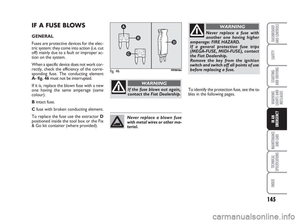
sponding fuse. The conducting element
A- fig. 46must not be interrupted.
If it is, replace the blown fuse with a new
one having the same amperage (same
colour).
Bintact fuse.
Cfuse with broken conducting element.
To replace the fuse use the extractor D
positioned inside the tool box or the Fix
& Go kit container (where provided).
If the fuse blows out again,
contact the Fiat Dealership.
WARNING
Never replace a fuse with
another one having higher
amperage: FIRE HAZARD.
If a general protection fuse trips
(MEGA-FUSE, MIDI-FUSE), contact
the Fiat Dealership.
Remove the key from the ignition
switch and switch off all points of use
before replacing a fuse.
WARNING
Never replace a blown fuse
with metal wires or other ma-
terial.
fig. 46FF0T0015m
To identify the protection fuse, see the ta-
bles in the following pages.
123-154 Fiorino GB 2ed 8-02-2008 15:27 Pagina 145
Page 150 of 210
149
SAFETY
MAINTENANCE
AND CARE
TECHNICAL
SPECIFICATIONS
INDEX
DASHBOARDAND CONTROLS
STARTING
AND DRIVING
WARNING
LIGHTS AND
MESSAGES
IN AN
EMERGENCY
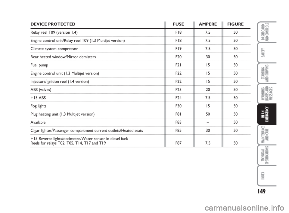
DEVICE PROTECTED FUSE AMPERE FIGURE
Relay reel T09 (version 1.4) F18 7.5 50
Engine control unit/Relay reel T09 (1.3 Multijet version) F18 7.5 50
Climate system compressor F19 7.5 50
Rear heated window/Mirror demisters F20 30 50
Fuel pump F21 15 50
Engine control unit (1.3 Multijet version) F22 15 50
Injectors/Ignition reel (1.4 version) F22 15 50
ABS (valves) F23 20 50
+15 ABS F24 7.5 50
Fog lights F30 15 50
Plug heating unit (1.3 Multijet version) F81 50 50
Available F83 – 50
Cigar lighter/Passenger compartment current outlets/Heated seats F85 30 50
+15 Reverse lights/decimetre/Water sensor in diesel fuel/
Reels for relays T02, T05, T14, T17 and T19 F87 7.5 50
123-154 Fiorino GB 2ed 8-02-2008 15:27 Pagina 149
Page 151 of 210
150
SAFETY
MAINTENANCE
AND CARE
TECHNICAL
SPECIFICATIONS
INDEX
DASHBOARDAND CONTROLS
STARTING
AND DRIVING
WARNING
LIGHTS AND
MESSAGES
IN AN
EMERGENCY
FUSES INSTALLED ON
PASSENGER COMPARTMENT
WIRED BOX
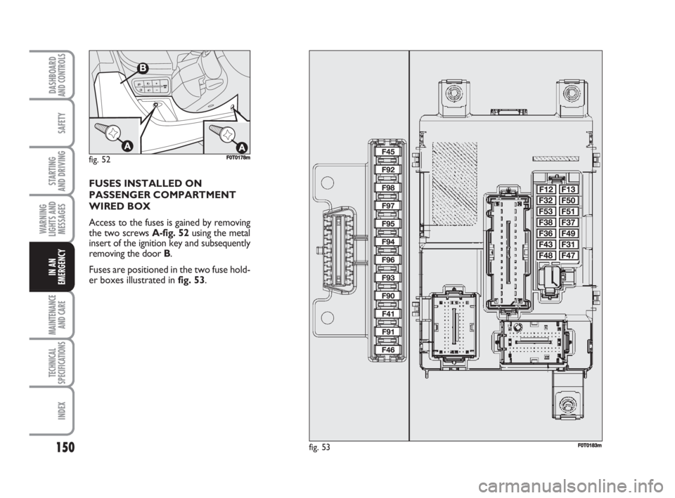
Access to the fuses is gained by removing
the two screws A-fig. 52 using the metal
insert of the ignition key and subsequently
removing the door B.
Fuses are positioned in the two fuse hold-
er boxes illustrated in fig. 53.
fig. 52F0T0178m
fig. 53F0T0183m
123-154 Fiorino GB 2ed 8-02-2008 15:27 Pagina 150
Page 155 of 210
154
SAFETY
MAINTENANCE
AND CARE
TECHNICAL
SPECIFICATIONS
INDEX
DASHBOARDAND CONTROLS
STARTING
AND DRIVING
WARNING
LIGHTS AND
MESSAGES
IN AN
EMERGENCY
IF THE VEHICLE NEEDS
TO BE TOWED
The tow ring supplied with the vehicle is
positioned in the tool box behind the left-
hand side backrest (on Cargo versions) or
in the boot (on Combi versions).
HOOKING THE TOW
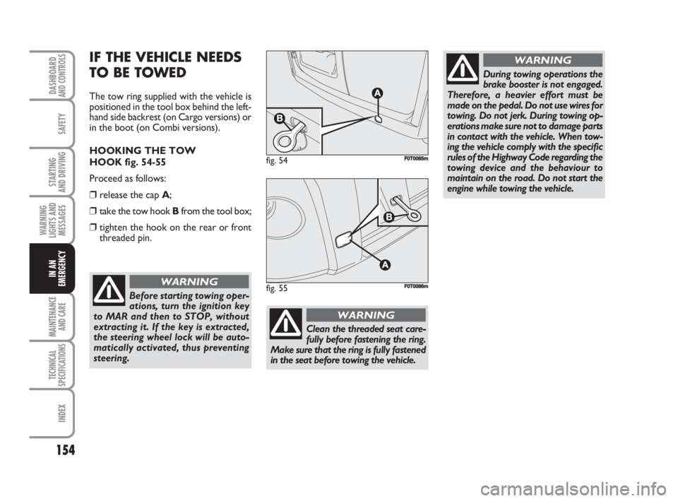
HOOK fig. 54-55
Proceed as follows:
❒release the cap A;
❒take the tow hook Bfrom the tool box;
❒tighten the hook on the rear or front
threaded pin.
fig. 54F0T0085m
fig. 55F0T0086m
Before starting towing oper-
ations, turn the ignition key
to MAR and then to STOP, without
extracting it. If the key is extracted,
the steering wheel lock will be auto-
matically activated, thus preventing
steering.
WARNING
During towing operations the
brake booster is not engaged.
Therefore, a heavier effort must be
made on the pedal. Do not use wires for
towing. Do not jerk. During towing op-
erations make sure not to damage parts
in contact with the vehicle. When tow-
ing the vehicle comply with the specific
rules of the Highway Code regarding the
towing device and the behaviour to
maintain on the road. Do not start the
engine while towing the vehicle.
WARNING
Clean the threaded seat care-
fully before fastening the ring.
Make sure that the ring is fully fastened
in the seat before towing the vehicle.
WARNING
123-154 Fiorino GB 2ed 8-02-2008 15:27 Pagina 154
Page 169 of 210
168
SAFETY
TECHNICAL
SPECIFICATIONS
INDEX
DASHBOARDAND CONTROLS
STARTING
AND DRIVING
WARNING
LIGHTS AND
MESSAGES
IN AN
EMERGENCY
MAINTENANCE
AND CARE
Batteries contain substances
that can be very dangerous
for the environment. It is ad-
visable to have the battery re-
placed by a Fiat Dealership where it
will be disposed of according to the
law.
Whenever an operation on
the battery or near it is re-
quired, always protect your eyes with
special goggles.
WARNING
If the vehicle remains unused
for a long time at very low
temperatures, remove the
battery and take it to a warm
place to avoid freezing.
USEFUL ADVICE
TO EXTEND THE LIFE OF YOUR
BATTERY
To avoid draining your battery and make
its life longer, observe the following indi-
cations:
❒when you park the vehicle, ensure the
doors, tailgate and bonnet are closed
properly;
❒switch off all lights inside the vehicle: the
vehicle is however equipped with a sys-
tem which switches all internal lights off
automatically;
❒do not keep accessories (e.g. sound sys-
tem, emergnecy lights, etc.) switched
on for a long time when the engine is
not running;
❒before performing any operation on the
electrical system, disconnect the bat-
tery negative cable;
❒battery terminals shall always be per-
fectly tightened.The battery is also more prone to the risk
of freezing (e.g. already at –10°C). Refer
to the paragraph “Vehicle inactivity” in
“Starting and driving” if the vehicle is left
parked for a long time.
If, after buying the vehicle, you want to in-
stall electric accessories which require
permanent electric supply (alarm, etc.)
contact the Fiat Dealership whose quali-
fied personnel, in addition to suggesting
the most suitable devices, will evaluate the
overall electric absorption, checking
whether the vehicle electric system is ca-
pable of withstanding the load required,
or whether it should be integrated with
a more powerful battery.
Since these devices continue absorbing en-
ergy even when the ignition key is off, they
gradually run down the battery.
155-176 Fiorino GB 2ed 8-02-2008 15:10 Pagina 168
Page 178 of 210
177
SAFETY
INDEX
DASHBOARDAND CONTROLS
STARTING
AND DRIVING
WARNING
LIGHTS AND
MESSAGES
IN AN
EMERGENCY
MAINTENANCE
AND CARE
TECHNICAL
SPECIFICATIONS
IDENTIFICATION DATA ................................................. 178
ENGINE CODES - BODYWORK VERSIONS............... 180
ENGINE .................................................................................. 181
FUEL FEED/IGNITION ....................................................... 182
TRANSMISSION .................................................................. 182
BRAKES................................................................................... 183
SUSPENSIONS ...................................................................... 183
STEERING .............................................................................. 183
WHEELS ................................................................................. 184
DIMENSIONS ....................................................................... 187
PERFORMANCE .................................................................. 189
WEIGHTS............................................................................... 190
CAPACITIES .......................................................................... 192
FLUIDS AND LUBRICANTS ............................................. 193
FUEL CONSUMPTION ...................................................... 195
CO
2EMISSIONS .................................................................. 195
RADIO FREQUENCY REMOTE CONTROL:
MINISTERIAL TYPE-APPROVALS ................................... 196
RIGHT HAND DRIVE VERSIONS ................................... 197
T T
E E
C C
H H
N N
I I
C C
A A
L L
S S
P P
E E
C C
I I
F F
I I
C C
A A
T T
I I
O O
N N
S S
177-198 Fiorino GB 2ed 8-02-2008 15:18 Pagina 177
Page 183 of 210
182
SAFETY
INDEX
DASHBOARDAND CONTROLS
STARTING
AND DRIVING
WARNING
LIGHTS AND
MESSAGES
IN AN
EMERGENCY
MAINTENANCE
AND CARE
TECHNICAL
SPECIFICATIONS
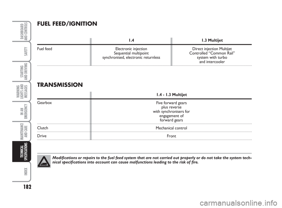
FUEL FEED/IGNITION
1.4 1.3 Multijet
Fuel feed Electronic injection Direct injection Multijet
Sequential multipoint Controlled “Common Rail”
synchronised, electronic returnless system with turbo
and intercooler
Modifications or repairs to the fuel feed system that are not carried out properly or do not take the system tech-
nical specifications into account can cause malfunctions leading to the risk of fire.
TRANSMISSION
1.4 - 1.3 Multijet
Gearbox
Clutch
DriveFive forward gears
plus reverse
with synchronisers for
engagement of
forward gears
Mechanical control
Front
177-198 Fiorino GB 2ed 8-02-2008 15:18 Pagina 182
Page 198 of 210
197
RIGHT HAND DRIVE VERSIONS
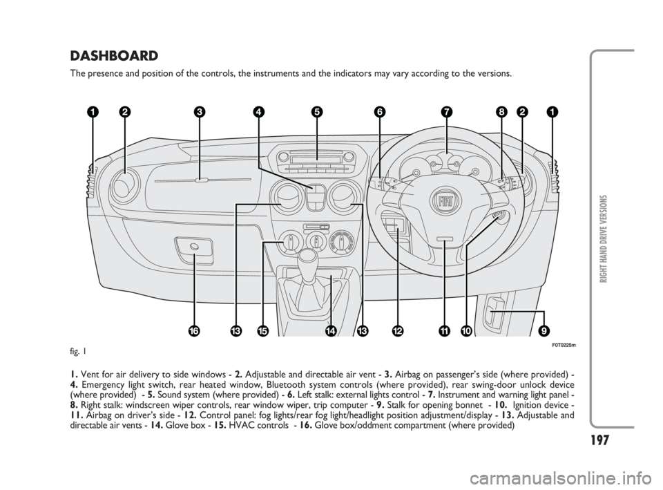
DASHBOARD
The presence and position of the controls, the instruments and the indicators may vary according to the versions.
1.Vent for air delivery to side windows - 2.Adjustable and directable air vent - 3.Airbag on passenger’s side (where provided) -
4.Emergency light switch, rear heated window, Bluetooth system controls (where provided), rear swing-door unlock device
(where provided) - 5.Sound system (where provided) - 6.Left stalk: external lights control - 7.Instrument and warning light panel -
8.Right stalk: windscreen wiper controls, rear window wiper, trip computer - 9.Stalk for opening bonnet - 10.Ignition device -
11.Airbag on driver’s side - 12.Control panel: fog lights/rear fog light/headlight position adjustment/display - 13.Adjustable and
directable air vents - 14.Glove box - 15.HVAC controls - 16.Glove box/oddment compartment (where provided)
F0T0225mfig. 1
177-198 Fiorino GB 2ed 8-02-2008 15:18 Pagina 197
Page 201 of 210
200
WARNING
LIGHTS AND
MESSAGES
DASHBOARDAND CONTROLS
SAFETY
STARTING
AND DRIVING
IN AN
EMERGENCY
MAINTENANCE
AND CARE
TECHNICAL
SPECIFICATIONS
INDEX
High beams
– bulb replacement .......................... 138
– control ............................................ 49
– flashing ............................................ 49
High mounted brake lights
– bulb replacement .......................... 141
Identification data .............................. 178
Ignition................................................... 182
In an emergency............................ 123
Instrument board ................................ 6
Instrument panel ................................. 5
Instruments .......................................... 15
Interior equipment ............................. 58
Interior .................................................. 175
Isofix seat ............................................. 93
Jack ........................................................ 129
Keys ...................................................... 8
Lamps
– bulb types ....................................... 135
– general ............................................ 134
– interior bulb replacement .......... 142
– outer lighting bulb replacement 137
Lane change function ......................... 50
Low beams
– bulb replacement .......................... 138
– control ............................................ 49
Luggage rack/ski rack ......................... 72
Maintenance and care................ 155 – heavy duty use of vehicle ............ 161
– routine checks .............................. 161
– routine maintenance .................... 156
– service plan .................................... 157
Manual AC system ............................. 46
Max. speeds ......................................... 189
Multifunctional display ....................... 22
Number plate light
– bulb replacement .......................... 141
Oddments compartment.................. 58
Outer lights .......................................... 49
Paintwork (maintenance) ................ 174
Park sensors ........................................ 77
Parking lights
– bulb replacement .......................... 137
– control ............................................ 49
Performance ........................................ 189
Power socket ...................................... 59
Prolonged inactivity ............................ 110
Radio transmitters
and mobile telephones .................... 80
Raising the vehicle .............................. 153
Rear fog light
– bulb replacement .......................... 140
– control rear roof lights ..... 143-144
Rear view mirrors
– external .......................................... 39 Fluids and lubricants ........................... 193
Fog lights
– bulb replacement .......................... 139
– control ............................................ 56
Follow me home (device) ................. 50
Front roof lights ........................142-143
Front seat arm rest ............................ 58
Fuel cap ................................................. 82
Fuel system .......................................... 182
Fuel
– consumption .................................. 195
– economy ......................................... 106
– system shutoff ............................... 57
Fuel feed ............................................... 182
Fuses (replacement) ........................... 145
Glass cleaning ..................................... 51
Glove box ............................................ 58
Handbrake .......................................... 104
Hazard warning lights ........................ 56
Head rests ............................................ 38
Headlamps
– beam adjustment abroad ............73
– beam alignment ............................. 73
– leveling ............................................ 73
– trim adjust ...................................... 73
Heater system/
Heating and ventilation ................... 43
199-208 Fiorino GB 2ed 8-02-2008 16:47 Pagina 200