technical data FIAT FIORINO 2010 Owner handbook (in English)
[x] Cancel search | Manufacturer: FIAT, Model Year: 2010, Model line: FIORINO, Model: FIAT FIORINO 2010Pages: 210, PDF Size: 4.9 MB
Page 24 of 210
23
SAFETY
STARTING
AND DRIVING
WARNING
LIGHTS AND
MESSAGES
IN AN
EMERGENCY
MAINTENANCE
AND CARE
TECHNICAL
SPECIFICATIONS
INDEX
DASHBOARD
AND CONTROLS
Day
YearMonth
Deutsch
Português
English
Español
Français
Italiano
Nederland
Turkçe Example:
fig. 18 Example:
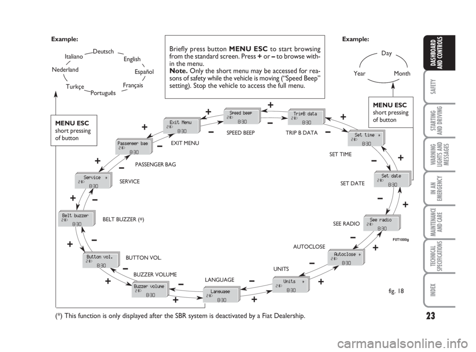
Briefly press button MENU ESCto start browsing
from the standard screen. Press +or –to browse with-
in the menu.
Note.Only the short menu may be accessed for rea-
sons of safety while the vehicle is moving (“Speed Beep”
setting). Stop the vehicle to access the full menu.
F0T1000g
MENU ESC
short pressing
of button
+
– +
–
– +
+
–
+–
–
– +
+++ ––––
++ +
– +
–
EXIT MENUSPEED BEEP
SET TIME
SET DATE
SEE RADIO
AUTOCLOSE
UNITS
LANGUAGE BUZZER VOLUME BUTTON VOL. BELT BUZZER (
*) SERVICEPASSENGER BAG
(*) This function is only displayed after the SBR system is deactivated by a Fiat Dealership.
–+
TRIP B DATA
MENU ESC
short pressing
of button
001-035 Fiorino GB 1ed:001-035 Fiorino GB 1ed 2-12-2009 16:14 Pagina 23
Page 25 of 210
24
SAFETY
STARTING
AND DRIVING
WARNING
LIGHTS AND
MESSAGES
IN AN
EMERGENCY
MAINTENANCE
AND CARE
TECHNICAL
SPECIFICATIONS
INDEX
DASHBOARD
AND CONTROLS
NoteThe speed may be set in the range
from 30 to 200 km/h, or from 20 to 125 mph
according to the previously chosen unit (see
“Setting the distance unit”) described below.
The setting will increase/decrease by five
units each time button +/ –is pressed. Hold
button +/–pressed to increase/decrease the
setting rapidly. Complete the setting by
briefly pressing the button when the required
setting is approached.
– Briefly press button MENU ESCto go
back to the menu screen or press the but-
ton for long to go back to the standard
screen without storing settings.
To cancel the setting, proceed as follows:
– briefly press button MENU ESC: (On)
will flash on the display;
– press button –: (Off) will flash on the dis-
play;
– briefly press button MENU ESCto go
back to the menu screen or press the but-
ton for long to go back to the standard
screen without storing settings. Speed limit (Speed Beep)
This function is used to set the vehicle
speed limit (km/h or mph); when this lim-
it is exceeded, the driver is immediately
alerted (see section “Warning lights and
messages”).
To set the speed limit, proceed as follows:
– briefly press button MENU ESC, the
display will show the wording (Speed
Beep);
– press button +or –to select speed lim-
it activation (On) or deactivation (Off);
– if the function has been activated (On),
press buttons +or –to select the re-
quired speed limit and then press MENU
ESCto confirm.Trip B On/Off (TripB data)
Through this option it is possible to acti-
vate (On) or deactivate (Off) the Trip B
(partial trip) display.
For further information see section “Trip
computer”.
For activation / deactivation, proceed as
follows:
– briefly press button MENU ESC: (On)
or (Off) will flash on the display (accord-
ing to previous setting);
– press button +or –for setting;
– briefly press button MENU ESCto go
back to the menu screen or press the but-
ton for long to go back to the standard
screen without storing settings.
001-035 Fiorino GB 1ed:001-035 Fiorino GB 1ed 2-12-2009 16:14 Pagina 24
Page 31 of 210
30
SAFETY
STARTING
AND DRIVING
WARNING
LIGHTS AND
MESSAGES
IN AN
EMERGENCY
MAINTENANCE
AND CARE
TECHNICAL
SPECIFICATIONS
INDEX
DASHBOARD
AND CONTROLS
TRIP COMPUTER
General features
The “Trip computer” is used to display in-
formation on vehicle operation when the
key is turned to MAR. This function al-
lows to define two separate trips called
“Trip A” and “Trip B” for monitoring the
“complete mission” of the vehicle (trip) in
a reciprocally independent manner. Both
functions are resettable (reset - start of
new mission).
“Trip A” is used to display data relating to:
– Range
– Trip distance
– Average consumption
– Instant consumption
– Average speed
– Travel time (driving time).“Trip B” is supplied on versions having a
multifunctional display and is used to dis-
play data relating to:
– Trip distance B
– Average consumption B
– Average speed B
– Travel time B (driving time).
Note“Trip B” functions may be disabled
(see paragraph “Trip B on”). “Range” and
“Instant consumption” cannot be reset. Exit Menu
This is the last function that closes the set-
ting cycle listed in the initial menu screen.
Briefly press button MENU ESCto go
back to the standard screen without stor-
ing settings.
Press button –to return to the first menu
option (Speed Beep).
001-035 Fiorino GB 1ed:001-035 Fiorino GB 1ed 2-12-2009 16:14 Pagina 30
Page 33 of 210
32
SAFETY
STARTING
AND DRIVING
WARNING
LIGHTS AND
MESSAGES
IN AN
EMERGENCY
MAINTENANCE
AND CARE
TECHNICAL
SPECIFICATIONS
INDEX
DASHBOARD
AND CONTROLS
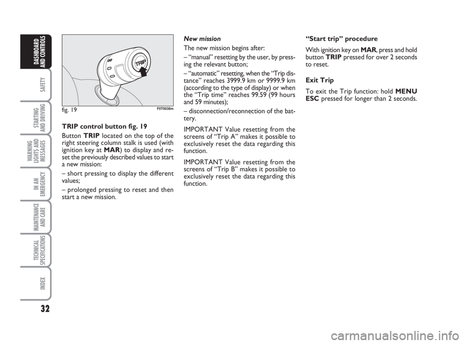
fig. 19F0T0038m
TRIP control button fig. 19
Button TRIPlocated on the top of the
right steering column stalk is used (with
ignition key at MAR) to display and re-
set the previously described values to start
a new mission:
– short pressing to display the different
values;
– prolonged pressing to reset and then
start a new mission.New mission
The new mission begins after:
– “manual” resetting by the user, by press-
ing the relevant button;
– “automatic” resetting, when the “Trip dis-
tance” reaches 3999.9 km or 9999.9 km
(according to the type of display) or when
the “Trip time” reaches 99.59 (99 hours
and 59 minutes);
– disconnection/reconnection of the bat-
tery.
IMPORTANT Value resetting from the
screens of “Trip A” makes it possible to
exclusively reset the data regarding this
function.
IMPORTANT Value resetting from the
screens of “Trip B” makes it possible to
exclusively reset the data regarding this
function.“Start trip” procedure
With ignition key on MAR, press and hold
button TRIPpressed for over 2 seconds
to reset.
Exit Trip
To exit the Trip function: hold MENU
ESCpressed for longer than 2 seconds.
001-035 Fiorino GB 1ed:001-035 Fiorino GB 1ed 2-12-2009 16:14 Pagina 32
Page 83 of 210
82
SAFETY
STARTING
AND DRIVING
WARNING
LIGHTS AND
MESSAGES
IN AN
EMERGENCY
MAINTENANCE
AND CARE
TECHNICAL
SPECIFICATIONS
INDEX
DASHBOARD
AND CONTROLS
ENVIRONMENTAL
PROTECTION
The devices for curtailing petrol engine
emissions are the following:
❒three-way catalytic converter;
❒Lambda sensors;
❒fuel evaporation prevention system.
In addition, do not let the engine run, even
for a test, with one or more spark plugs
disconnected.
The devices for curtailing diesel fuel en-
gine emissions are the following:
❒oxidising catalytic converter;
❒exhaust gas recirculation system
(E.G.R.);
❒diesel particulate filter (DPF) (for ver-
sions/markets, where provided). Do not place free flames or lit
cigarettes near to the fuel
filler: this may pose a risk of
fire. Keep your face away
from the fuel filler to prevent breath-
ing in harmful vapours.
DIESEL PARTICULATE
FILTER DPF
(Diesel Particulate Filter)
(for versions/markets, where provided)
The Diesel Particulate Filter is a mechan-
ical filter integral with the exhaust system
that physically traps carbon particles pre-
sent in the exhaust gases of Diesel engines.
The diesel particulate filter has been
adopted to eliminate particulates almost
totally in compliance with current / future
law regulations. During normal use of the
vehicle, the engine control unit records a
set of data (e.g.: travel time, type of route,
temperatures, etc.) and it will then calcu-
late the amount of particles trapped by the
filter.
Since this filter physically traps particulates,
it shall be cleaned (reclaimed) at regular
intervals by burning carbon particles. The
regeneration procedure is controlled au-
tomatically by the engine control unit ac-
cording to the filter conditions and the
conditions of use of the vehicle.
During the regeneration procedure, the
following situations may occur: limited in-
crease of idle speed, activation of electric
fan, limited increase of smoke, high tem-
peratures at the exhaust. These events
must not be considered as a malfunction-
ing: they do not impair vehicle behaviour
and the environment. If the dedicated
message is displayed, refer to section
“Warning lights and messages”. Closing
1) Fit the cap (complete with key) and turn
it clockwise until it clicks once or more.
2) Turn the key clockwise and extract it,
then close the flap.
The hermetic seal may cause a slight in-
crease in pressure in the tank. A suction
noise when you release the cap is there-
fore entirely normal.
036-082 Fiorino GB 1ed:036-082 Fiorino GB 1ed 30-11-2009 15:47 Pagina 82
Page 90 of 210
89
STARTING
AND DRIVING
WARNING
LIGHTS AND
MESSAGES
IN AN
EMERGENCY
MAINTENANCE
AND CARE
TECHNICAL
SPECIFICATIONS
INDEX
DASHBOARDAND CONTROLS
SAFETY
CARRYING
CHILDREN SAFELY
For optimal protection in the event of a
crash, all passengers must be seated and
wear adequate restraint systems.
This is even more important for children.
This prescription is compulsory in all EC
countries according to EC Directive
2003/20/EC.
A child’s head is larger and heavier in pro-
portion to his/her body and the child’s
muscular and bone structures are not ful-
ly developed. For this reason, they require
restraint systems which are different from
those used by adults to protect them in
the event of an accident.The research results in relation to the best
protection for children is illustrated in Eu-
ropean standard CEE-R44 which divides
the restraint systems into five groups in
addition to making their use compulsory:
Group 0 = up to 10 kg in weight
Group 0+ = up to 13 kg in weight
Group 1 = 9-18 kg in weight
Group 2 = 15-25 kg in weight
Group 3 = 22-36 kg in weight
As it may be noted, the groups overlap
partly and, in fact, in commerce it is pos-
sible to find devices that cover more than
one weight group.All restraint devices must bear the type-
approval data along with the control mark
on a label that must be firmly secured to
the child seat and must never be removed.
Over 1.50 m in height, from the point of
view of restraint systems, children are
considered as adults and have to wear the
standard seat belts.
Lineaccessori Fiat includes child restraint
systems for each weight group. These de-
vices are recommended as they have been
specifically designed for Fiat cars/vehicles.
083-100 Fiorino GB 1ed:083-100 Fiorino GB 1ed 30-11-2009 15:53 Pagina 89
Page 178 of 210
177
SAFETY
INDEX
DASHBOARDAND CONTROLS
STARTING
AND DRIVING
WARNING
LIGHTS AND
MESSAGES
IN AN
EMERGENCY
MAINTENANCE
AND CARE
TECHNICAL
SPECIFICATIONS
IDENTIFICATION DATA ................................................. 178
ENGINE CODES - BODYWORK VERSIONS ............... 180
ENGINE .................................................................................. 181
FUEL FEED/IGNITION ....................................................... 182
TRANSMISSION .................................................................. 182
BRAKES................................................................................... 183
SUSPENSIONS ...................................................................... 183
STEERING .............................................................................. 183
WHEELS ................................................................................. 184
DIMENSIONS ....................................................................... 187
PERFORMANCE .................................................................. 189
WEIGHTS............................................................................... 190
CAPACITIES .......................................................................... 192
FLUIDS AND LUBRICANTS ............................................. 193
FUEL CONSUMPTION ...................................................... 195
CO
2EMISSIONS .................................................................. 196
RADIO FREQUENCY REMOTE CONTROL:
MINISTERIAL TYPE-APPROVALS ................................... 197
T T
E E
C C
H H
N N
I I
C C
A A
L L
S S
P P
E E
C C
I I
F F
I I
C C
A A
T T
I I
O O
N N
S S
177-199 Fiorino GB 1ed:177-201 Fiorino GB 1ed 4-12-2009 9:42 Pagina 177
Page 179 of 210
178
SAFETY
INDEX
DASHBOARDAND CONTROLS
STARTING
AND DRIVING
WARNING
LIGHTS AND
MESSAGES
IN AN
EMERGENCY
MAINTENANCE
AND CARE
TECHNICAL
SPECIFICATIONS
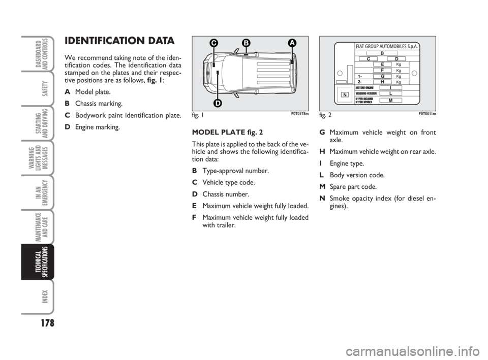
MODEL PLATE fig. 2
This plate is applied to the back of the ve-
hicle and shows the following identifica-
tion data:
BType-approval number.
CVehicle type code.
DChassis number.
EMaximum vehicle weight fully loaded.
FMaximum vehicle weight fully loaded
with trailer.GMaximum vehicle weight on front
axle.
HMaximum vehicle weight on rear axle.
IEngine type.
LBody version code.
MSpare part code.
NSmoke opacity index (for diesel en-
gines).
IDENTIFICATION DATA
We recommend taking note of the iden-
tification codes. The identification data
stamped on the plates and their respec-
tive positions are as follows, fig. 1:
AModel plate.
BChassis marking.
CBodywork paint identification plate.
DEngine marking.
fig. 1F0T0175mfig. 2F0T0011m
177-199 Fiorino GB 1ed:177-201 Fiorino GB 1ed 4-12-2009 9:42 Pagina 178
Page 180 of 210
179
SAFETY
INDEX
DASHBOARDAND CONTROLS
STARTING
AND DRIVING
WARNING
LIGHTS AND
MESSAGES
IN AN
EMERGENCY
MAINTENANCE
AND CARE
TECHNICAL
SPECIFICATIONS
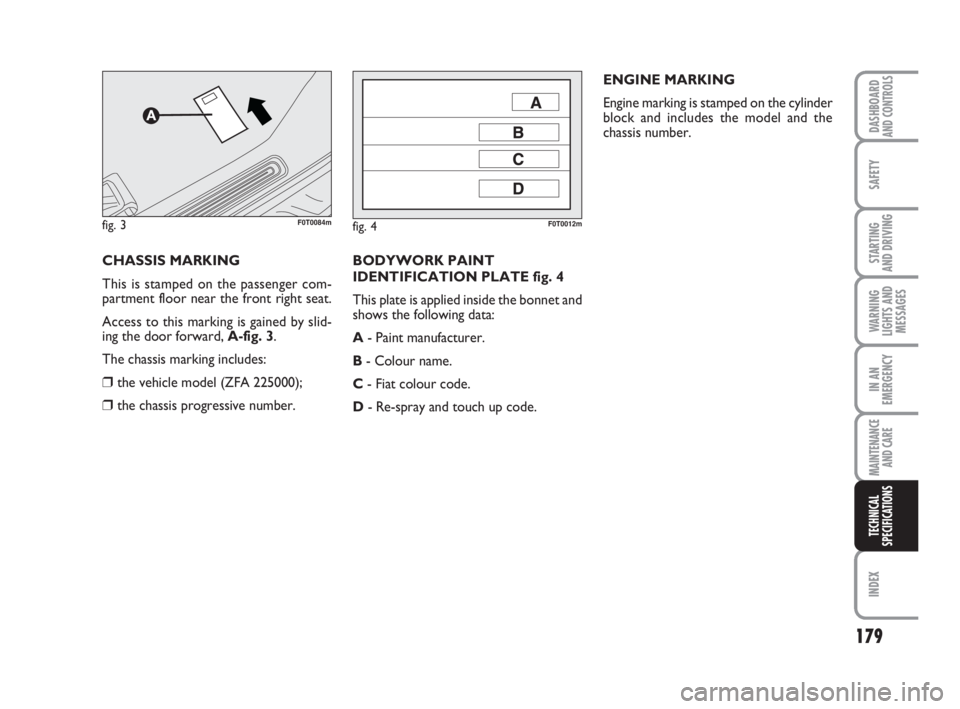
BODYWORK PAINT
IDENTIFICATION PLATE fig. 4
This plate is applied inside the bonnet and
shows the following data:
A- Paint manufacturer.
B- Colour name.
C- Fiat colour code.
D- Re-spray and touch up code.ENGINE MARKING
Engine marking is stamped on the cylinder
block and includes the model and the
chassis number.
CHASSIS MARKING
This is stamped on the passenger com-
partment floor near the front right seat.
Access to this marking is gained by slid-
ing the door forward, A-fig. 3.
The chassis marking includes:
❒the vehicle model (ZFA 225000);
❒the chassis progressive number.
fig. 4F0T0012mfig. 3F0T0084m
177-199 Fiorino GB 1ed:177-201 Fiorino GB 1ed 4-12-2009 9:42 Pagina 179
Page 202 of 210
201
WARNING
LIGHTS AND
MESSAGES
DASHBOARDAND CONTROLS
SAFETY
STARTING
AND DRIVING
IN AN
EMERGENCY
MAINTENANCE
AND CARE
TECHNICAL
SPECIFICATIONS
INDEX
– beam alignment ................................ 70
– leveling ............................................... 70
– trim adjust ......................................... 70
Heater system/
Heating and ventilation ...................... 43
High beams
– bulb replacement ............................. 138
– control ............................................... 49
– flashing ............................................... 49
High mounted brake lights
– bulb replacement ............................. 141
Hill Holder system ................................. 73
Identification data .................................. 178
Ignition device ......................................... 13
In an emergency................................ 123
Instrument board ................................... 6
Instrument panel .................................... 5
Instruments ............................................. 14
Interior equipment ................................ 56
Interior ..................................................... 176
Isofix seat (provision for installation) 93
Jack ............................................................ 129
Keys
– mechanical key ................................. 8
– key with remote control ............... 8Lamps
– bulb types .......................................... 135
– general ............................................... 134
– interior bulb replacement .............. 142
– outer lighting bulb replacement ... 137
Lane change function ............................. 50
Level checks ............................................ 162
Low beams
– bulb replacement ............................. 138
– control ............................................... 49
Luggage rack/ski rack ............................ 72
Maintenance and care..................... 155
Manual AC system ................................. 46
Max. speeds ............................................. 189
MSR system ............................................. 74
Multi/function display ............................ 21
Number plate light
– bulb replacement ............................. 141
Oddments tray ....................................... 56
Outer lights ............................................. 49
Paintwork (maintenance) ..................... 174
Park sensors ............................................ 77 EOBD system ......................................... 76
ESP system ............................................... 72
Fiat CODE (system) ............................. 7
Fix&Go (device) ..................................... 130
Fluids and lubricants .............................. 193
Fog lights
– bulb replacement ............................. 139
– control ............................................... 55
Follow me home (device) .................... 50
Front roof lights ...........................142-143
Front seat arm rest ............................... 56
Fuel cap .................................................... 81
Fuel system .............................................. 182
Fuel
– consumption ..................................... 195
– economy ............................................ 106
– system shutoff .................................. 56
Fuses (replacement) .............................. 145
Glass cleaning ......................................... 51
Glove box ................................................ 56
Handbrake ............................................... 104
Hazard warning lights ............................ 55
Head rests ............................................... 38
Headlamps
– beam adjustment abroad ............... 70
200-208 Fiorino GB 1ed:202-208 Fiorino GB 1ed 2-12-2009 16:32 Pagina 201