engine FIAT FIORINO 2019 Owner handbook (in English)
[x] Cancel search | Manufacturer: FIAT, Model Year: 2019, Model line: FIORINO, Model: FIAT FIORINO 2019Pages: 220, PDF Size: 6.22 MB
Page 106 of 220

CRUISE CONTROL
(constant speed
regulator)
(for versions/markets, where provided)
This is an electronic driving aid that
allows you to drive at a speed of above
30 km/h on long and straight dry roads
with few driving changes (e.g.
motorways) at a preset speed without
having to press the accelerator pedal. It
is therefore not recommended to use
this device on extra-urban roads with
traffic. Do not use the device in town.
Turning the device on
When the device is activated, light
comes on together with the relevant
message on the instrument panel (for
versions/markets, where provided).
The speed adjustment function cannot
be activated in 1
stor reverse gear; it
is advisable to activate the function in
4
thor higher gears.
When travelling downhill with the device
activated, the vehicle speed may
exceed the memorised one.
Storing vehicle speed
Proceed as follows:
turn ring nut A fig. 111 to the ON
position and press the accelerator
pedal so that the vehicle reaches the
desired speed;
move the stalk upwards (+) for at
least one second, then release it. The
vehicle speed is now stored and you
can therefore release the accelerator
pedal.
If necessary (e.g. when overtaking)
acceleration is possible by simply
pressing the accelerator pedal:
releasing the accelerator pedal the car
will return to the speed stored
previously.
Restoring the stored speed
If the device has been deactivated, for
example by depressing the brake or
clutch pedal, the stored speed can be
restored as follows:
accelerate progressively until a
speed close to that stored is reached;
engage the gear selected at the time
that the speed was stored;
press button B fig. 111.Increasing the stored speed
This can be done in two ways:
by pressing the accelerator and
storing the new speed reached
or
by moving the stalk upwards (+).
Each activation of the lever
corresponds to an increase in speed of
about 1 km/h, whilst keeping the lever
upwards varies the speed continuously.
Reducing the memorised speed
This can be done in two ways:
by deactivating the device and then
storing the new speed
or
by moving the stalk downwards (-)
until the new speed, which will be
stored automatically, is reached.
Each movement of the stalk will
correspond to a slight reduction in
speed of about 1 km/h, while keeping
the stalk held downwards will decrease
the speed continuously.
Turning the device off
The device can be switched off by the
driver in the following ways:
by turning ring nut A to the OFF
position;
by switching off the engine;
111F0T0405
104
STARTING AND DRIVING
Page 110 of 220
Start&Stop SYSTEM
(for versions/markets, where provided)
106) 107) 108) 109)
IN BRIEF
The Start&Stop device automatically
stops the engine each time the
vehicle is stationary and all the
conditions for automatic switch-off
have been met, and starts it again
when the driver wants to move off.
This improves the efficiency of the
vehicle by reducing fuel consumption,
the emission of harmful gases and
noise pollution.
OPERATING MODE
Stopping the engine
Versions with manual transmission
With the vehicle stationary, the engine
stops with the gearbox in neutral and
the clutch pedal released.Versions with Comfort-matic
transmission
With the vehicle stationary and the
brake pedal pressed, the engine stops
if the gear lever is in position other
thanR. In the event of stops uphill,
engine switching off is disabled to make
the "Hill Holder" function available
(works only with the engine running).
The warning light on the instrument
panel switches on to signal that the
engine has stopped.
Restarting the engine
Versions with manual transmission
Depress the clutch pedal to restart
the engine.
Versions with Comfort-matic
transmission
Releasing the brake pedal the engine
restarts automatically; the icon switches
off on the display. If the engine is
restarted with the “Hill Holder” function
off, move the lever towards (+), (-)or
Rand the engine restarts.MANUAL ACTIVATION
AND DEACTIVATION
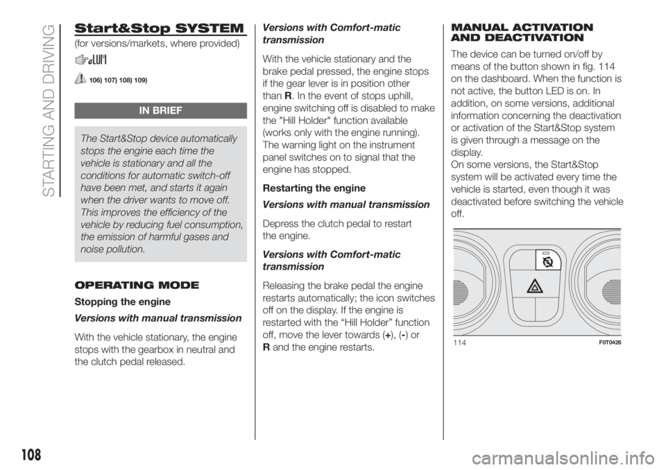
The device can be turned on/off by
means of the button shown in fig. 114
on the dashboard. When the function is
not active, the button LED is on. In
addition, on some versions, additional
information concerning the deactivation
or activation of the Start&Stop system
is given through a message on the
display.
On some versions, the Start&Stop
system will be activated every time the
vehicle is started, even though it was
deactivated before switching the vehicle
off.
114F0T0426
108
STARTING AND DRIVING
Page 111 of 220
SAFETY FUNCTIONS
In engine cut-out conditions through
the Start&Stop system, if the driver
unfastens his/her seat belt and opens
the driver's door or the passenger door,
the engine can be restarted only by
using the key. The driver is notified of
this condition by a buzzer, through the
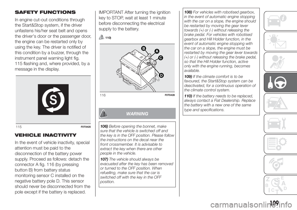
instrument panel warning light fig.
115 flashing and, where provided, by a
message in the display.
VEHICLE INACTIVITY
In the event of vehicle inactivity, special
attention must be paid to the
disconnection of the battery power
supply. Proceed as follows: detach the
connector A fig. 116 (by pressing
button B) from battery status
monitoring sensor C installed on the
negative battery pole D. This sensor
should never be disconnected from the
pole except if the battery is replaced.IMPORTANT After turning the ignition
key to STOP, wait at least 1 minute
before disconnecting the electrical
supply to the battery.
110)
WARNING
106)Before opening the bonnet, make
sure that the vehicle is switched off and
the key is in the OFF position. Please follow
the instructions on the decal near the
front crossmember. It is advisable to
extract the key when there are other
people in the vehicle.
107)The vehicle should always be
evacuated after the key has been removed
or turned to the OFF position. When
refuelling, make sure that the car is
switched off with the key in the OFF
position.108)For vehicles with robotised gearbox,
in the event of automatic engine stopping
with the car on a slope, the engine should
be restarted by moving the gear lever
towards (+) or (-) without releasing the
brake pedal. For vehicles with robotised
gearbox and Hill Holder function, in the
event of automatic engine stopping with
the car on a slope, the engine must be
restarted by moving the gear lever towards
(+) or (-) without releasing the brake pedal,
so that the Hill Holder function, active
only with the engine running, becomes
available.
109)If the climate comfort is to be
favoured, the Start&Stop system can be
deactivated, for a continuous operation of
the climate control system.
110)If the battery needs to be replaced,
always contact a Fiat Dealership. Replace
the battery with a new one of the same
type and specifications.115F0T0425
116F0T0428
109
Page 112 of 220
REFUELLING THE
VEHICLE
111)
25) 26)
PETROL ENGINES
Use unleaded petrol only, with an
octane number (R.O.N.) not lower than
95.
IMPORTANT Never introduce leaded
petrol to the tank, even in small
amounts in an emergency, as this
would damage the catalytic converter
beyond repair.
DIESEL ENGINES
Only use Diesel for motor vehicles
(EN590 specification).
Operation at low temperatures
In order to avoid these problems,
different types of diesel are distributed
according to the season: summer type,
winter type and arctic type (cold/
mountain areas).If refuelling with diesel whose
specifications are not suitable for the
usage temperature, it is advisable
to mix PETRONAS DURANCE DIESEL
ART additive in the proportions shown
on the container with the fuel. Pour
the additive into the tank before the
fuel.
When using or parking the vehicle for a
long time in the mountains or cold
areas, it is advisable to refuel using
locally available diesel fuel.
In this case, it is also advisable to keep
the tank over 50% full.
REFUELLING CAPACITY
To ensure that you fill the tank
completely, top up twice after the first
click of the fuel supply gun. Further
top-ups could cause faults in the fuel
feeding system.
FUEL TANK CAPOpening
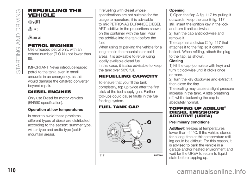
1) Open the flap A fig. 117 by pulling it
outwards, keep the cap B fig. 117
still, insert the ignition key in the lock
and turn it anticlockwise.
2) Turn the cap anticlockwise and
remove it.
The cap has a device C fig. 117 that
attaches it to the flap so it cannot
be lost. When refilling, attach the plug
to the flap, as shown.
Closing
1) Fit the cap (complete with key) and
turn it clockwise until it clicks once
or more.
2) Turn the key clockwise and extract it,
then close the flap.
The sealing may cause a slight pressure
increase in the tank. A little breathing
off, while slackening the cap is
absolutely normal.
TOPPING UP ADBLUE
®
DIESEL EMISSIONS
ADDITIVE (UREA)
Preliminary conditions
AdBlue® freezes at temperatures
lower than -11°C. If the vehicle stands
for a long time at this temperature refill-
ing could be difficult. For this reason, it
is advised to park the vehicle in a
garage and/or heated environment and
wait for the UREA to return to liquid
state before topping up.
117F0T0068
110
STARTING AND DRIVING
Page 113 of 220
Proceed as follows:
park the vehicle on ground level;
stop the engine by turning the
ignition device to MAR;
open the bonnet by pulling the lever
under the dashboard on driver's side
(see "Engine bonnet" paragraph in the
"Knowing your car" chapter) and
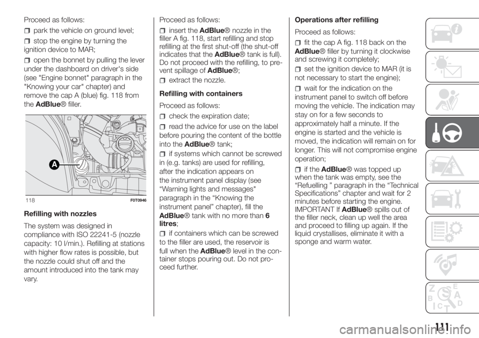
remove the cap A (blue) fig. 118 from
theAdBlue® filler.
Refilling with nozzles
The system was designed in
compliance with ISO 22241-5 (nozzle
capacity: 10 l/min.). Refilling at stations
with higher flow rates is possible, but
the nozzle could shut off and the
amount introduced into the tank may
vary.Proceed as follows:
insert theAdBlue® nozzle in the
filler A fig. 118, start refilling and stop
refilling at the first shut-off (the shut-off
indicates that theAdBlue® tank is full).
Do not proceed with the refilling, to pre-
vent spillage ofAdBlue®;
extract the nozzle.
Refilling with containers
Proceed as follows:
check the expiration date;
read the advice for use on the label
before pouring the content of the bottle
into theAdBlue® tank;
if systems which cannot be screwed
in (e.g. tanks) are used for refilling,
after the indication appears on
the instrument panel display (see
“Warning lights and messages"
paragraph in the “Knowing the
instrument panel” chapter), fill the
AdBlue® tank with no more than
litres;
if containers which can be screwed
to the filler are used, the reservoir is
full when theAdBlue® level in the con-
tainer stops pouring out. Do not pro-
ceed further.Operations after refilling
Proceed as follows:
fit the cap A fig. 118 back on the
AdBlue® filler by turning it clockwise
and screwing it completely;
set the ignition device to MAR (it is
not necessary to start the engine);
wait for the indication on the
instrument panel to switch off before
moving the vehicle. The indication may
stay on for a few seconds to
approximately half a minute. If the
engine is started and the vehicle is
moved, the indication will remain on for
longer. This will not compromise engine
operation;
if theAdBlue® was topped up
when the tank was empty, see the
“Refuelling ” paragraph in the “Technical
Specifications” chapter and wait for 2
minutes before starting the engine.
IMPORTANT IfAdBlue® spills out of
the filler neck, clean up well the area
and proceed to filling up again. If the
liquid crystallises, eliminate it with a
sponge and warm water.A
118F0T0946
111
6
Page 114 of 220
IMPORTANT
DO NOT EXCEED THE
MAXIMUM LEVEL: this could cause
damage to the reservoir. UREA
freezes at under -11 °C. Although
the system is designed to operate
below the freezing point of the
UREA, it is advisable not to fill the
tank beyond the maximum level
because if the UREA freezes the
system can be damaged. Follow the
instructions in the “Topping up
AdBlue® diesel emissions additive
(UREA)” paragraph in this chapter.
If the UREA is spilled on painted
surfaces or aluminium, immediately
clean the area with water and use
absorbent material to collect the
fluid that has been spilled on the
ground.
Do not try to start the engine if
UREA was accidentally added to
the Diesel fuel tank, this can result
in serious engine damage, contact
a Fiat Dealership.
Do not add additives or other
fluids to AdBlue®, doing so could
damage the system.
The use of non-conforming or
degraded AdBlue® may lead to
indications appearing on the instru-
ment panel display (see “Warning
lights and messages" paragraph in
the “Knowing the instrument panel”
chapter).
Never pour AdBlue® into
another container: it could be con-
taminated.
In case of damage to the
sewage system of exhaust gas
resulting from the use of additives /
tap water, the introduction of diesel
fuel, or at least by not fulfilling the
requirements, the warranty expires.
If the AdBlue® runs out, see
“Warning lights and messages"
paragraph in the “Knowing the
instrument panel” chapter to con-
tinue using the vehicle normally.
AdBlue® (UREA) storage
AdBlue® (UREA) is a very stable prod-
uct with a long shelf life. Stored at tem-
peratures LOWER than 32 °C, it has a
shelf life of at least one year.
Follow the instructions on the label of
the container.
112)
METHANE ENGINES
(NATURAL POWER)
METHANE GAS FILLER
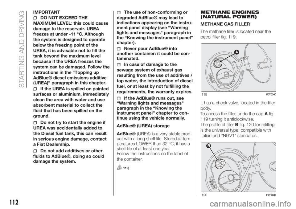
The methane filler is located near the
petrol filler fig. 119.
It has a check valve, located in the filler
body.
To access the filler, undo the capAfig.
119 turning it anticlockwise.
The profile of fillerBfig. 120 for refilling
is the universal type, compatible with
Italian and "NGV1" standards.
119F0T0360
120F0T0336
112
STARTING AND DRIVING
Page 116 of 220
WARNING
111)Do not bring naked flames or lit
cigarettes near to the fuel filler: fire risk.
Keep your face away from the fuel filler to
prevent breathing in harmful vapours.
112)If
AdBlue® overheats for a pro-
longed period inside the tank to over 50 °C
(for example, due to direct solar irradiation),
AdBlue® can decompose ammonia
vapours. Ammonia vapours have a pungent
odour when the cap of the
AdBlue®tank
is unscrewed, therefore be careful not to
inhale any ammonia vapours in the tank
outlet. In this concentration, however, the
ammonia vapors are not harmful or danger-
ous to health.
WARNING
25)For diesel engines, use only diesel fuel
for motor vehicles in accordance with
EN590 European specifications. The use of
other products or mixtures may damage
the engine beyond repair and
consequently invalidate the warranty, due
to the damage caused. If you accidentally
introduce other types of fuel into the tank,
do not start the engine. Empty the tank.
If the engine has been run for even an
extremely limited amount of time, you must
not only drain the fuel tank, but the rest of
the supply circuit as well.26)You must not open the right sliding side
door with the fuel cap open while
refuelling. Check that the fuel cap is closed
while opening/closing the sliding side
door.
27)Methane refuelling stations are not
authorised to refill the cylinders when the
inspection date has expired. The check
valve prevents the methane from flowing
back to the fuel filler.
AdBlue®(UREA)
ADDITIVE FOR
DIESEL EMISSIONS
The vehicle is equipped with an UREA
fuel injection system and a Selective
Catalytic Reduction catalyst to meet the
emission standards.
These two systems ensure compliance
with the diesel emissions requirements;
at the same time, they ensure
fuel-efficiency, handling, torque and
power. For messages and system
warnings, refer to the "Warning lights
and messages" paragraph in the
"Knowing the instrument panel"
chapter.
AdBlue® (UREA) is a very stable prod-
uct with a long shelf life. Stored at tem-
peratures LOWER than 32 °C, it has a
shelf life of at least one year.
For more information on theAdBlue®
liquid type, see the “Fluids and lubri-
cants” paragraph in the “Technical
specifications” chapter.
The vehicle is provided with an
automaticAdBlue® heating system
when the engine starts allowing the
system to work correctly at tempera-
tures lower than -11 °C.
IMPORTANTAdBlue® freezes at tem-
peratures lower than -11 °C.
114
STARTING AND DRIVING
Page 120 of 220
WHEEL REPLACEMENT
PROCEDURE
To change a wheel, proceed as follows:
stop the vehicle in a position that is
not dangerous for oncoming traffic
where you can change the wheel safely.
The ground must be flat and sufficiently
compact;
switch off the engine and pull the
handbrake;
engage first gear or reverse;
wear the reflective safety jacket
(compulsory by law in certain countries)
before getting out of the vehicle;
indicate that the vehicle has broken
down using the devices required by
the law in the current country (e.g.
warning triangle, hazard lights, etc.);
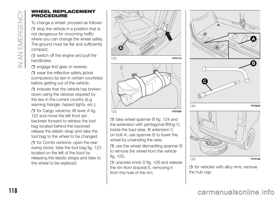
for Cargo versions: lift lever A fig.
122 and move the left front set
backrest forward to retrieve the tool
bag located behind the backrest:
release the elastic strap and take the
tool bag to the wheel to be changed;
for Combi versions: open the rear
swing doors, take the tool bag fig. 123
located on the left of the boot by
releasing the elastic straps and take to
the wheel to be replaced;
take wheel spanner B fig. 124 and
the extension with pentagonal fitting C;
inside the load area, fit extension C
on bolt A; use spanner B to lower the
wheel by unwinding the wire;
use the wheel dismantling spanner B
to remove the wheel from the vehicle
fig. 125;
unscrew knob D fig. 126 and release
the rim from bracket E, removing it
from the hole of the rim;for vehicles with alloy rims, remove
the hub cap;
122F0T0119
123F0T0206
124F0T0922
125F0T0168
118
IN AN EMERGENCY
Page 123 of 220
117)The space-saver wheel (for
versions/markets, where provided) is
specific to your vehicle, do not use it on
other models, or use the space-saver
wheel of other models on your vehicle. The
space-saver wheel must only be used in
the event of an emergency. Never use it for
more than strictly necessary and never
exceed 80 km/h. "Warning! For temporary
use only! 80km/h max! Replace with
standard wheel as soon as possible. Never
remove or cover the sticker on the
space-saver wheel. Never apply a wheel
cap on a space-saver wheel. The driving
characteristics of the vehicle will be
modified with the space-saver wheel fitted.
Avoid violent acceleration and braking,
abrupt steering and fast cornering.
118)Use your hazard lights, warning
triangle, etc to show that your vehicle is
stationary. Passengers should get out
of the vehicle, particularly if it is heavily
loaded, and wait for the wheel to be
changed away from the traffic. If you are on
a slope or uneven surface, place wedges
or other suitable objects under the wheels
to secure the vehicle. Have the wheel
repaired and refitted as soon as possible.
Do not apply grease to the bolt threads
before fitting: they could come unscrewed.119)The jack is a tool developed and
designed only for changing a wheel, if a
tyre gets punctured or damaged, on the
vehicle with which it is supplied or on other
vehicles of the same model. Any other
use, e.g. to jack up other vehicle models or
different things, is strictly prohibited. Never
use it to carry out maintenance or repairs
under the vehicle or to change summer/
winter wheels and vice versa: we advise
you to contact a Fiat Dealership. Never go
under the raised vehicle: use it only in
the positions indicated. Do not use the jack
for loads higher than the one shown on
its label. Never start the engine with vehicle
raised. If the vehicle is raised more than
necessary, everything can become more
unstable, with the risk of the vehicle
dropping violently. Thus, lift the vehicle only
as needed in order to access the spare
wheel.
120)Incorrect hub cap assembly may
cause it to come off when the vehicle is
moving. Never tamper with the inflation
valve. Never introduce tools of any kind
between rim and tyre. Check tyre and
space-saver wheel pressures regularly,
referring to the values shown in the
"Technical data" chapter.
WARNING
28)When turning the jack handle make
sure that it can turn freely without scraping
your hand against the ground. The moving
components of the jack ("worm screw"
and joints) can also cause injuries: do not
touch them. If you come into contact
with lubricating grease, clean yourself
thoroughly.
29)Contact a Fiat Dealership as soon as
possible to have the correct tightening
of the fixing bolts checked.
121
Page 124 of 220
FIX&GO
AUTOMATIC KIT
121) 122)
30)
The Fix&Go automatic quick tyre repair
kit is located in a special container in
the boot.
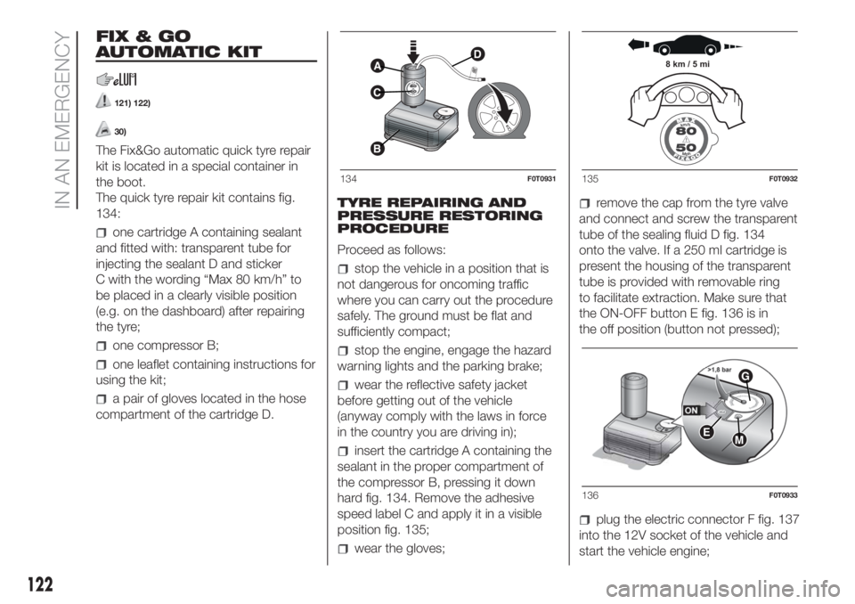
The quick tyre repair kit contains fig.
134:
one cartridge A containing sealant
and fitted with: transparent tube for
injecting the sealant D and sticker
C with the wording “Max 80 km/h” to
be placed in a clearly visible position
(e.g. on the dashboard) after repairing
the tyre;
one compressor B;
one leaflet containing instructions for
using the kit;
a pair of gloves located in the hose
compartment of the cartridge D.TYRE REPAIRING AND
PRESSURE RESTORING
PROCEDURE
Proceed as follows:
stop the vehicle in a position that is
not dangerous for oncoming traffic
where you can carry out the procedure
safely. The ground must be flat and
sufficiently compact;
stop the engine, engage the hazard
warning lights and the parking brake;
wear the reflective safety jacket
before getting out of the vehicle
(anyway comply with the laws in force
in the country you are driving in);
insert the cartridge A containing the
sealant in the proper compartment of
the compressor B, pressing it down
hard fig. 134. Remove the adhesive
speed label C and apply it in a visible
position fig. 135;
wear the gloves;
remove the cap from the tyre valve
and connect and screw the transparent
tube of the sealing fluid D fig. 134
onto the valve. If a 250 ml cartridge is
present the housing of the transparent
tube is provided with removable ring
to facilitate extraction. Make sure that
the ON-OFF button E fig. 136 is in
the off position (button not pressed);
plug the electric connector F fig. 137
into the 12V socket of the vehicle and
start the vehicle engine;
A
C
B
D
134F0T0931
8 km / 5 mi
135F0T0932
EM
G
136F0T0933
122
IN AN EMERGENCY