ignition FIAT FREEMONT 2011 Owner handbook (in English)
[x] Cancel search | Manufacturer: FIAT, Model Year: 2011, Model line: FREEMONT, Model: FIAT FREEMONT 2011Pages: 267, PDF Size: 5.16 MB
Page 80 of 267
HEADLIGHT WASHERS — IF EQUIPPED
The Headlight Washers are recessed into the top of
the fascia, centrally located below each headlight.
The windshield wiper/washer control lever operates
the headlight washers when the ignition switch is in the
ON position and the headlights are ON. The lever is
located on the left side of the steering column.
To use the headlight washers, push the washer knob,
located on the end of the multifunction lever, inward to
the second detent to activate the windshield washers
and release it. When this is done, the two stationary
washer nozzles at each headlight spray one timed
high-pressure spray of washer fluid onto each headlight
lens. In addition, the windshield washers will spray the
windshield and the windshield wipers will cycle.
NOTE:After turning the ignition switch and head-
lights ON, the headlight washers will operate on the
first spray of the windshield washer and then every
eleventh spray after that. REAR WINDOW FEATURES
REAR WINDOW WIPER/WASHER
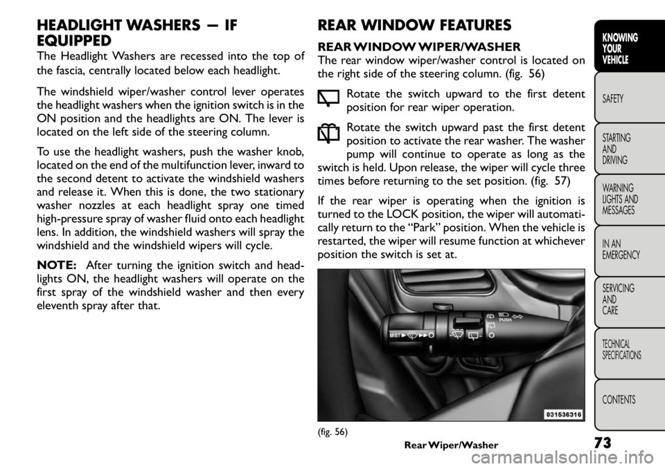
The rear window wiper/washer control is located on
the right side of the steering column. (fig. 56)
Rotate the switch upward to the first detent
position for rear wiper operation.
Rotate the switch upward past the first detent
position to activate the rear washer. The washer
pump will continue to operate as long as the
switch is held. Upon release, the wiper will cycle three
times before returning to the set position. (fig. 57)
If the rear wiper is operating when the ignition is
turned to the LOCK position, the wiper will automati-
cally return to the “Park” position. When the vehicle is
restarted, the wiper will resume function at whichever
position the switch is set at.
(fig. 56) Rear Wiper/Washer
73KNOWING
YOURVEHICLESAFETY
STARTING ANDDRIVING
WARNING
LIGHTS AND
MESSAGES
IN AN
EMERGENCY
SERVICING AND
CARETECHNICAL
SPECIFICATIONSCONTENTS
Page 82 of 267
ELECTRONIC SPEED CONTROL — IF EQUIPPED
When engaged, the Electronic Speed Control takes
over accelerator operations at speeds greater than
40 km/h.
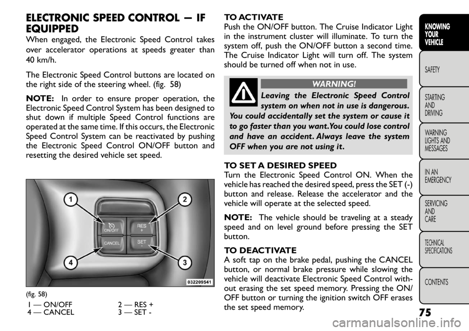
The Electronic Speed Control buttons are located on
the right side of the steering wheel. (fig. 58)
NOTE:In order to ensure proper operation, the
Electronic Speed Control System has been designed to
shut down if multiple Speed Control functions are
operated at the same time. If this occurs, the Electronic
Speed Control System can be reactivated by pushing
the Electronic Speed Control ON/OFF button and
resetting the desired vehicle set speed. TO ACTIVATE
Push the ON/OFF button. The Cruise Indicator Light
in the instrument cluster will illuminate. To turn the
system off, push the ON/OFF button a second time.
The Cruise Indicator Light will turn off. The system
should be turned off when not in use.
WARNING!
Leaving the Electronic Speed Control
system on when not in use is dangerous.
You could accidentally set the system or cause it
to go faster than you want .You could lose control
and have an accident . Always leave the system
OFF when you are not using it .
TO SET A DESIRED SPEED
Turn the Electronic Speed Control ON. When the
vehicle has reached the desired speed, press the SET (-)
button and release. Release the accelerator and the
vehicle will operate at the selected speed.
NOTE: The vehicle should be traveling at a steady
speed and on level ground before pressing the SET
button.
TO DEACTIVATE
A soft tap on the brake pedal, pushing the CANCEL
button, or normal brake pressure while slowing the
vehicle will deactivate Electronic Speed Control with-
out erasing the set speed memory. Pressing the ON/
OFF button or turning the ignition switch OFF erases
the set speed memory.
(fig. 58)
1 — ON/OFF 2 — RES +
4 — CANCEL 3 — SET - 75
KNOWING
YOURVEHICLESAFETY
STARTING ANDDRIVING
WARNING
LIGHTS AND
MESSAGES
IN AN
EMERGENCY
SERVICING AND
CARETECHNICAL
SPECIFICATIONSCONTENTS
Page 85 of 267
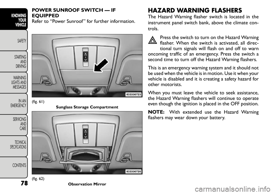
POWER SUNROOF SWITCH — IF EQUIPPED
Refer to “Power Sunroof ” for further information.HAZARD WARNING FLASHERS
The Hazard Warning flasher switch is located in the
instrument panel switch bank, above the climate con-
trols.
Press the switch to turn on the Hazard Warning
flasher. When the switch is activated, all direc-
tional turn signals will flash on and off to warn
oncoming traffic of an emergency. Press the switch a
second time to turn off the Hazard Warning flashers.
This is an emergency warning system and it should not
be used when the vehicle is in motion. Use it when your
vehicle is disabled and it is creating a safety hazard for
other motorists.
When you must leave the vehicle to seek assistance,
the Hazard Warning flashers will continue to operate
even though the ignition is placed in the OFF position.
NOTE: With extended use the Hazard Warning
flashers may wear down your battery.(fig. 61)
Sunglass Storage Compartment(fig. 62) Observation Mirror
78
KNOWINGYOUR
VEHICLE
SAFETY
STARTING AND
DRIVING
WARNING
LIGHTS AND
MESSAGES
IN AN
EMERGENCY
SERVICING AND
CARETECHNICAL
SPECIFICATIONSCONTENTS
Page 89 of 267
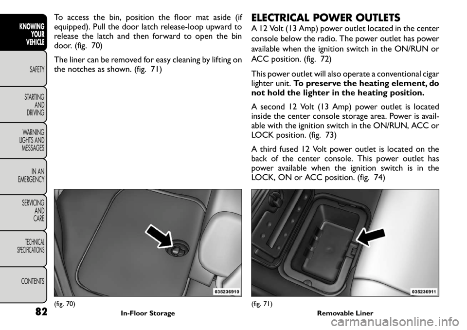
To access the bin, position the floor mat aside (if
equipped). Pull the door latch release-loop upward to
release the latch and then forward to open the bin
door. (fig. 70)
The liner can be removed for easy cleaning by lifting on
the notches as shown. (fig. 71)ELECTRICAL POWER OUTLETS
A 12 Volt (13 Amp) power outlet located in the center
console below the radio. The power outlet has power
available when the ignition switch in the ON/RUN or
ACC position. (fig. 72)
This power outlet will also operate a conventional cigar
lighter unit.
To preserve the heating element, do
not hold the lighter in the heating position.
A second 12 Volt (13 Amp) power outlet is located
inside the center console storage area. Power is avail-
able with the ignition switch in the ON/RUN, ACC or
LOCK position. (fig. 73)
A third fused 12 Volt power outlet is located on the
back of the center console. This power outlet has
power available when the ignition switch is in the
LOCK, ON or ACC position. (fig. 74)(fig. 70) In-Floor Storage
(fig. 71)Removable Liner
82
KNOWING
YOUR
VEHICLE
SAFETY
STARTING AND
DRIVING
WARNING
LIGHTS AND
MESSAGES
IN AN
EMERGENCY
SERVICING AND
CARETECHNICAL
SPECIFICATIONSCONTENTS
Page 90 of 267
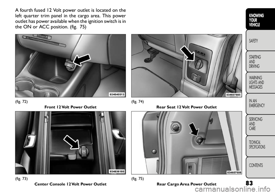
A fourth fused 12 Volt power outlet is located on the
left quarter trim panel in the cargo area. This power
outlet has power available when the ignition switch is in
the ON or ACC position. (fig. 75)(fig. 72)Front 12 Volt Power Outlet(fig. 73)Center Console 12 Volt Power Outlet
(fig. 74)
Rear Seat 12 Volt Power Outlet(fig. 75) Rear Cargo Area Power Outlet 83
KNOWING
YOURVEHICLESAFETY
STARTING ANDDRIVING
WARNING
LIGHTS AND
MESSAGES
IN AN
EMERGENCY
SERVICING AND
CARETECHNICAL
SPECIFICATIONSCONTENTS
Page 94 of 267
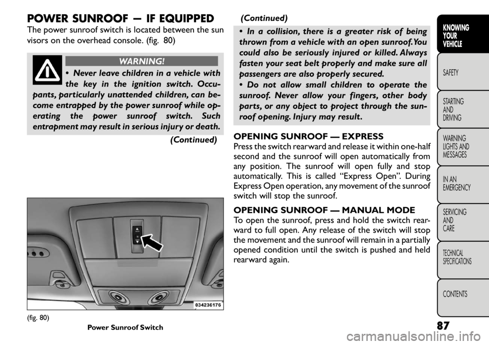
POWER SUNROOF — IF EQUIPPED
The power sunroof switch is located between the sun
visors on the overhead console. (fig. 80)
WARNING!
Never leave children in a vehicle with
the key in the ignition switch. Occu-
pants, particularly unattended children, can be-
come entrapped by the power sunroof while op-
erating the power sunroof switch. Such
entrapment may result in serious injury or death.
(Continued)(Continued)
In a collision, there is a greater risk of being
thrown from a vehicle with an open sunroof.You
could also be seriously injured or killed. Always
fasten your seat belt properly and make sure all
passengers are also properly secured.
Do not allow small children to operate the
sunroof. Never allow your fingers, other body
parts, or any object to project through the sun-
roof opening. Injury may result .
OPENING SUNROOF — EXPRESS
Press the switch rearward and release it within one-half
second and the sunroof will open automatically from
any position. The sunroof will open fully and stop
automatically. This is called “Express Open”. During
Express Open operation, any movement of the sunroof
switch will stop the sunroof.
OPENING SUNROOF — MANUAL MODE
To open the sunroof, press and hold the switch rear-
ward to full open. Any release of the switch will stop
the movement and the sunroof will remain in a partially
opened condition until the switch is pushed and held
rearward again.
(fig. 80) Power Sunroof Switch 87
KNOWING
YOURVEHICLESAFETY
STARTING ANDDRIVING
WARNING
LIGHTS AND
MESSAGES
IN AN
EMERGENCY
SERVICING AND
CARETECHNICAL
SPECIFICATIONSCONTENTS
Page 96 of 267
SUNROOF MAINTENANCE
Use only a nonabrasive cleaner and a soft cloth to clean
the glass panel.
IGNITION OFF OPERATION
The power sunroof switches remain active for up to
approximately ten minutes after the ignition switch has
been turned OFF. Opening either front door will cancel
this feature.
NOTE:The delay time is programmable using the
Uconnect Touch™ system. Refer to “Uconnect
Touch™ Settings” for further information. DOOR LOCKS
MANUAL DOOR LOCKS
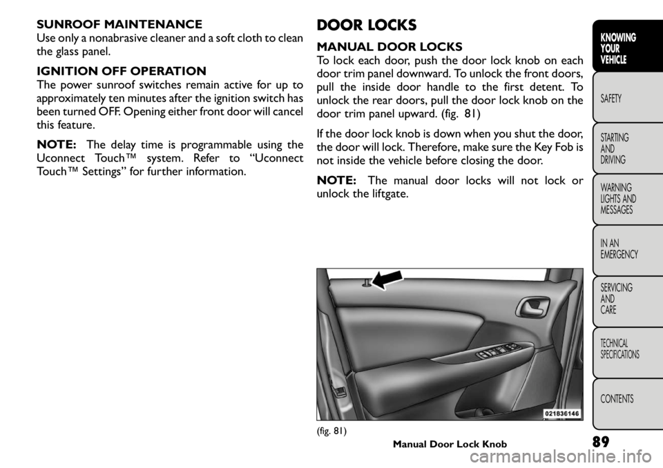
To lock each door, push the door lock knob on each
door trim panel downward. To unlock the front doors,
pull the inside door handle to the first detent. To
unlock the rear doors, pull the door lock knob on the
door trim panel upward. (fig. 81)
If the door lock knob is down when you shut the door,
the door will lock. Therefore, make sure the Key Fob is
not inside the vehicle before closing the door.
NOTE:
The manual door locks will not lock or
unlock the liftgate.
(fig. 81) Manual Door Lock Knob 89
KNOWING
YOURVEHICLESAFETY
STARTING ANDDRIVING
WARNING
LIGHTS AND
MESSAGES
IN AN
EMERGENCY
SERVICING AND
CARETECHNICAL
SPECIFICATIONSCONTENTS
Page 97 of 267
WARNING!
For personal security and safety in the
event of an accident , lock the vehicle
doors before you drive as well as when you park
and leave the vehicle.
When leaving the vehicle, always remove the
Key Fob from the vehicle and lock your vehicle.
Unsupervised use of vehicle equipment may
cause severe personal injuries or death.
Never leave children alone in a vehicle. Leaving
unattended children in a vehicle is dangerous for
a number of reasons. A child or others could be
seriously or fatally injured. Do not leave the Key
Fob in the ignition. A child could operate power
windows, other controls, or move the vehicle.
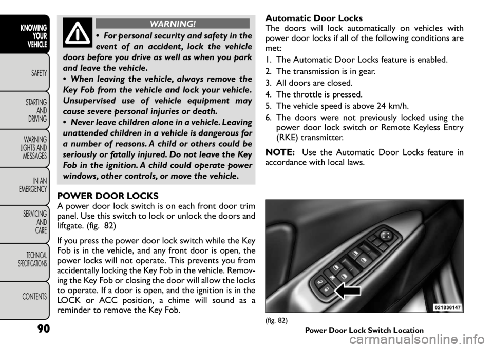
POWER DOOR LOCKS
A power door lock switch is on each front door trim
panel. Use this switch to lock or unlock the doors and
liftgate. (fig. 82)
If you press the power door lock switch while the Key
Fob is in the vehicle, and any front door is open, the
power locks will not operate. This prevents you from
accidentally locking the Key Fob in the vehicle. Remov-
ing the Key Fob or closing the door will allow the locks
to operate. If a door is open, and the ignition is in the
LOCK or ACC position, a chime will sound as a
reminder to remove the Key Fob. Automatic Door Locks
The doors will lock automatically on vehicles with
power door locks if all of the following conditions aremet:
1. The Automatic Door Locks feature is enabled.
2. The transmission is in gear.
3. All doors are closed.
4. The throttle is pressed.
5. The vehicle speed is above 24 km/h.
6. The doors were not previously locked using the
power door lock switch or Remote Keyless Entry
(RKE) transmitter.
NOTE: Use the Automatic Door Locks feature in
accordance with local laws.
(fig. 82) Power Door Lock Switch Location
90
KNOWING
YOUR
VEHICLE
SAFETY
STARTING AND
DRIVING
WARNING
LIGHTS AND
MESSAGES
IN AN
EMERGENCY
SERVICING AND
CARETECHNICAL
SPECIFICATIONSCONTENTS
Page 98 of 267

Automatic Unlock Doors On Exit
The doors will unlock automatically on vehicles with
power door locks if:
1. The Automatic Unlock Doors On Exit feature isenabled.
2. The transmission was in gear and the vehicle speed returned to 0 km/h.
3. The transmission is in NEUTRAL or PARK.
4. The driver door is opened.
5. The doors were not previously unlocked.
6. The vehicle speed is 0 km/h.
To change the current setting, refer to “Uconnect
Touch™ Settings” in “Knowing Your Vehicle” for fur-
ther information.
NOTE: Use the Automatic Unlock Doors On Exit
feature in accordance with local laws.
Automatic Unlock Doors On Exit
Programming
The Automatic Unlock Doors On Exit feature can be
enabled or disabled as follows:
• For vehicles equipped with the Uconnect Touch™, refer to “Uconnect Touch™ Settings” in “Knowing
Your Vehicle” for further information. • For vehicles not equipped with the Uconnect
Touch™, perform the following steps:
1. Enter the vehicle and close all doors.
2. Place the Key Fob in the ignition switch.
3. Within 15 seconds, cycle the ignition switch be- tween LOCK and ON/RUN and then back to LOCK
four times ending up in the LOCK position. How-
ever, do not start the engine.
4. Within 30 seconds, press the power door unlock switch to unlock the doors.
5. A single chime will indicate the completion of the programming.
NOTE: If you do not hear the chime, it means that
the system did not enter the programming mode and
you will need to repeat the procedure.
6. Repeat these steps if you want to return this feature to its previous setting.
NOTE: Use the Automatic Unlock Doors On Exit
feature in accordance with local laws.
91
KNOWING
YOURVEHICLESAFETY
STARTING ANDDRIVING
WARNING
LIGHTS AND
MESSAGES
IN AN
EMERGENCY
SERVICING AND
CARETECHNICAL
SPECIFICATIONSCONTENTS
Page 101 of 267
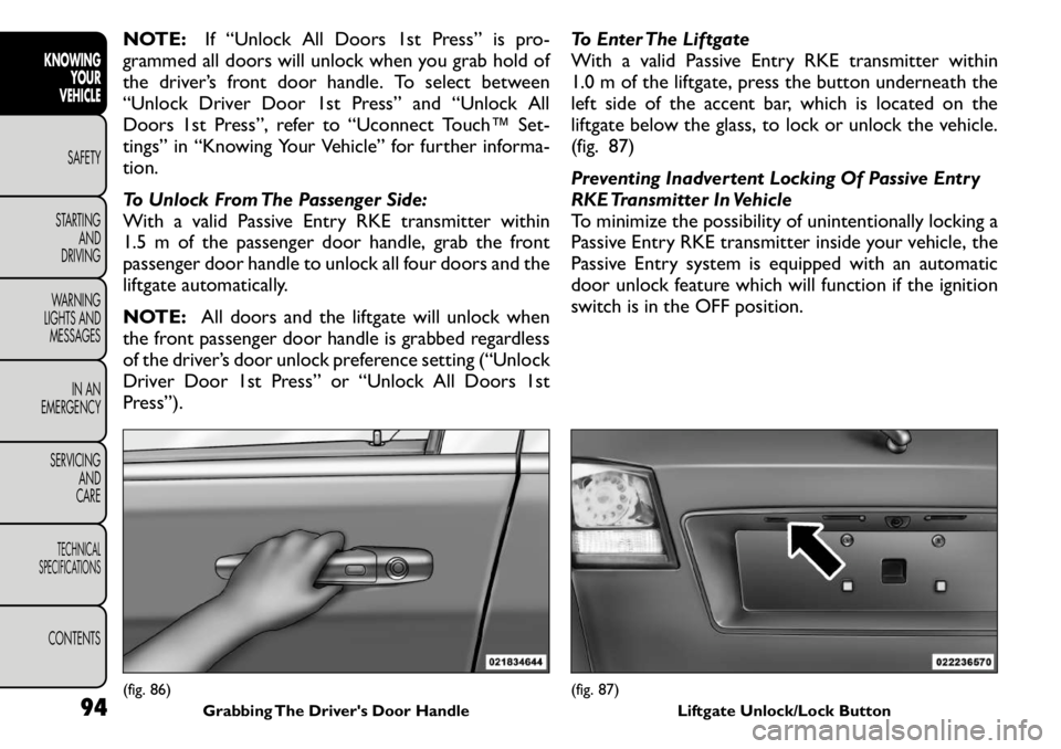
NOTE:If “Unlock All Doors 1st Press” is pro-
grammed all doors will unlock when you grab hold of
the driver’s front door handle. To select between
“Unlock Driver Door 1st Press” and “Unlock All
Doors 1st Press”, refer to “Uconnect Touch™ Set-
tings” in “Knowing Your Vehicle” for further informa-tion.
To Unlock From The Passenger Side:
With a valid Passive Entry RKE transmitter within
1.5 m of the passenger door handle, grab the front
passenger door handle to unlock all four doors and the
liftgate automatically.
NOTE: All doors and the liftgate will unlock when
the front passenger door handle is grabbed regardless
of the driver’s door unlock preference setting (“Unlock
Driver Door 1st Press” or “Unlock All Doors 1st
Press”). To Enter The Liftgate
With a valid Passive Entry RKE transmitter within
1.0 m of the liftgate, press the button underneath the
left side of the accent bar, which is located on the
liftgate below the glass, to lock or unlock the vehicle.
(fig. 87)
Preventing Inadvertent Locking Of Passive Entry
RKE Transmitter In Vehicle
To minimize the possibility of unintentionally locking a
Passive Entry RKE transmitter inside your vehicle, the
Passive Entry system is equipped with an automatic
door unlock feature which will function if the ignition
switch is in the OFF position.(fig. 86)
Grabbing The Driver's Door Handle
(fig. 87) Liftgate Unlock/Lock Button
94
KNOWING
YOUR
VEHICLE
SAFETY
STARTING AND
DRIVING
WARNING
LIGHTS AND
MESSAGES
IN AN
EMERGENCY
SERVICING AND
CARETECHNICAL
SPECIFICATIONSCONTENTS