stop start FIAT FREEMONT 2011 Owner handbook (in English)
[x] Cancel search | Manufacturer: FIAT, Model Year: 2011, Model line: FREEMONT, Model: FIAT FREEMONT 2011Pages: 267, PDF Size: 5.16 MB
Page 194 of 267
vehicle has tires of a different size than the size indi-
cated on the vehicle placard or tire inflation pressure
label, you should determine the proper tire inflation
pressure for those tires.)
As an added safety feature, your vehicle has been
equipped with a tire pressure monitoring system
(TPMS) that illuminates a low tire pressure telltale
when one or more of your tires is significantly under-
inflated. Accordingly, when the low tire pressure tell-
tale light illuminates, you should stop and check your
tires as soon as possible, and inflate them to the proper
pressure. Driving on a significantly under-inflated tire
causes the tire to overheat and can lead to tire failure.
Under-inflation also reduces fuel efficiency and tire
tread life, and may affect the vehicle’s handling and
stopping ability.
Please note that the TPMS is not a substitute for
proper tire maintenance, and it is the driver’s respon-
sibility to maintain correct tire pressure, even if under-
inflation has not reached the level to trigger illumina-
tion of the TPMS low tire pressure telltale.
Your vehicle has also been equipped with a TPMS
malfunction indicator to indicate when the system is
not operating properly. The TPMS malfunction indica-
tor is combined with the low tire pressure telltale.
When the system detects a malfunction, the telltale
will flash for approximately one minute and then re-
main continuously illuminated. This sequence will con-
tinue upon subsequent vehicle start-ups as long as the
malfunction exists. When the malfunction indicator isilluminated, the system may not be able to detect or
signal low tire pressure as intended. TPMS malfunctions
may occur for a variety of reasons, including the instal-
lation of replacement or alternate tires or wheels on
the vehicle that prevent the TPMS from functioning
properly. Always check the TPMS malfunction telltale
light after replacing one or more tires or wheels on
your vehicle to ensure that the replacement or alter-
nate tires and wheels allow the TPMS to continue to
function properly.
The TPMS has been optimized for the
original equipment tires and wheels.
TPMS pressures and warning have been
established for the tire size equipped on your
vehicle. Undesirable system operation or sensor
damage may result when using replacement
equipment that is not of the same size, type,
and/or style.Aftermarket wheels can cause sensor
damage. Do not use aftermarket tire sealants or
balance beads if your vehicle is equipped with a
TPMS, as damage to the sensors may result . (Re-
fer to “Tire Inflation Pressures” under “Tires —
General Information” and to “Tire Pressure Moni-
tor System (TPMS)” in “Technical Specifications”
for further information).
10. Seat Belt Reminder Light When the ignition switch is first turned to ON/
RUN, this light will turn on for four to eight
seconds as a bulb check. During the bulb check,
187KNOWING
YOURVEHICLE SAFETY
STARTING ANDDRIVINGWARNING
LIGHTS AND
MESSAGESIN AN
EMERGENCY
SERVICING AND
CARETECHNICAL
SPECIFICATIONSCONTENTS
Page 195 of 267
if the driver's seat belt is unbuckled, a chime will sound.
After the bulb check or when driving, if the driver seat
belt remains unbuckled, the Seat Belt Warning Light
will flash or remain on continuously. Refer to “Occu-
pant Restraints” in “Safety” for further information.
11. Brake Warning LightThis light monitors various brake functions,
including brake fluid level and parking brake
application. If the brake light turns on it may
indicate that the parking brake is applied, that
the brake fluid level is low, or that there is a problem
with the anti-lock brake system reservoir.
If the light remains on when the parking brake has been
disengaged, and the fluid level is at the full mark on the
master cylinder reservoir, it indicates a possible brake
hydraulic system malfunction or that a problem with
the Brake Booster has been detected by the Anti-Lock
Brake System (ABS) / Electronic Stability Program
(ESP) system. In this case, the light will remain on until
the condition has been corrected. If the problem is
related to the brake booster, the ABS pump will run
when applying the brake and a brake pedal pulsation
may be felt during each stop.
The dual brake system provides a reserve braking
capacity in the event of a failure to a portion of the
hydraulic system. A leak in either half of the dual brake
system is indicated by the Brake Warning Light, which
will turn on when the brake fluid level in the master
cylinder has dropped below a specified level.
The light will remain on until the cause is corrected. NOTE:
The light may flash momentarily during sharp
cornering maneuvers, which change fluid level condi-
tions. The vehicle should have service performed, and
the brake fluid level checked.
If brake failure is indicated, immediate repair is neces-
sary.
WARNING!
Driving a vehicle with the red brake light
on is dangerous. Part of the brake sys-
tem may have failed. It will take longer to stop
the vehicle. You could have a collision. Have the
vehicle checked immediately.
Vehicles equipped with the Anti-Lock Brake System
(ABS), are also equipped with Electronic Brake Force
Distribution (EBD). In the event of an EBD failure, the
Brake Warning Light will turn on along with the ABS
Light. Immediate repair to the ABS system is required.
Operation of the Brake Warning Light can be checked
by turning the ignition switch from the OFF position to
the ON/RUN position. The light should illuminate for
approximately two seconds. The light should then turn
off unless the parking brake is applied or a brake fault is
detected. If the light does not illuminate, have the light
inspected by an authorized dealer.
The light also will turn on when the parking brake is
applied with the ignition switch in the ON/RUN posi-tion.
188
KNOWING YOUR
VEHICLE
SAFETY
STARTING AND
DRIVINGWARNING
LIGHTS AND
MESSAGES
IN AN
EMERGENCY
SERVICING AND
CARETECHNICAL
SPECIFICATIONSCONTENTS
Page 210 of 267
4. Firmly grasp the bulb by the two side latches andsqueeze them together to unlock the bulb from the
back of the lamp housing.
5. Pull the bulb straight out from the keyed opening in the housing
6. Remove the bulb from the connector socket and install the replacement bulb.
7. Align the index tabs of the replacement rear fog lamp bulb/socket assembly with the slots in the
collar of the bulb opening on the back of the lamphousing.
8. Insert bulb into the lamp housing until the index tabs are engaged in the slots of the collar.
9. Firmly and evenly push the bulb straight into the lamp housing until both side latches lock firmly into
place.
10. Reinstall the fog lamp housing.
SIDE REPEATER LAMP
The side repeater lamps are located in both front
fender panels.
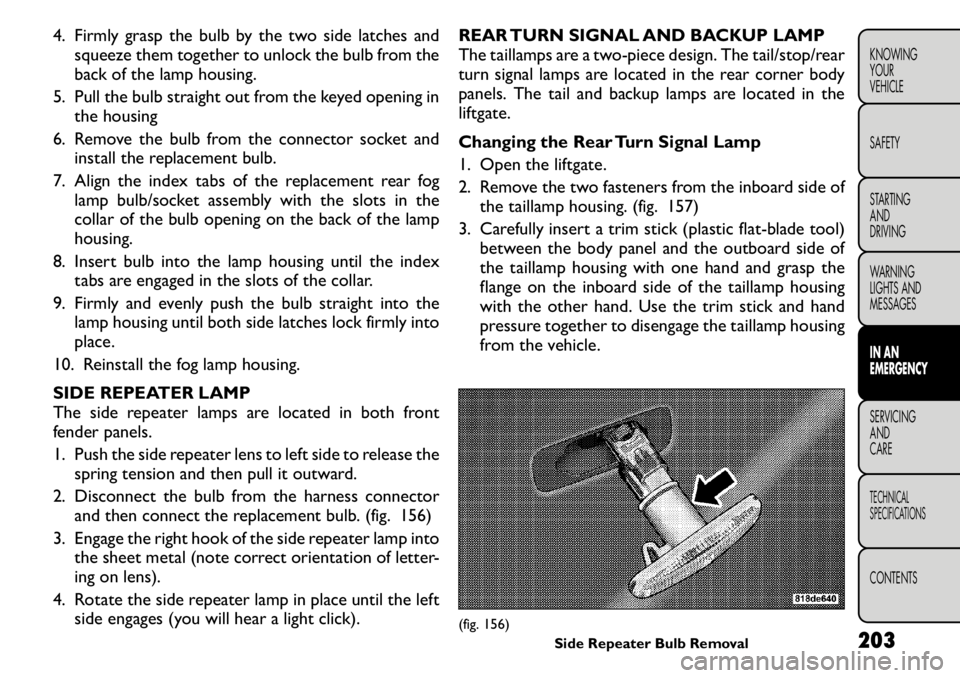
1. Push the side repeater lens to left side to release the spring tension and then pull it outward.
2. Disconnect the bulb from the harness connector and then connect the replacement bulb. (fig. 156)
3. Engage the right hook of the side repeater lamp into the sheet metal (note correct orientation of letter-
ing on lens).
4. Rotate the side repeater lamp in place until the left side engages (you will hear a light click). REAR TURN SIGNAL AND BACKUP LAMP
The taillamps are a two-piece design. The tail/stop/rear
turn signal lamps are located in the rear corner body
panels. The tail and backup lamps are located in the
liftgate.
Changing the Rear Turn Signal Lamp
1. Open the liftgate.
2. Remove the two fasteners from the inboard side of
the taillamp housing. (fig. 157)
3. Carefully insert a trim stick (plastic flat-blade tool) between the body panel and the outboard side of
the taillamp housing with one hand and grasp the
flange on the inboard side of the taillamp housing
with the other hand. Use the trim stick and hand
pressure together to disengage the taillamp housing
from the vehicle.
(fig. 156) Side Repeater Bulb Removal 203
KNOWING
YOURVEHICLE SAFETY
STARTING ANDDRIVING
WARNING
LIGHTS AND
MESSAGESIN AN
EMERGENCYSERVICING AND
CARETECHNICAL
SPECIFICATIONSCONTENTS
Page 217 of 267
FREEING A STUCK VEHICLE
If your vehicle becomes stuck in mud, sand, or snow, it
can often be moved by a rocking motion. Turn your
steering wheel right and left to clear the area around
the front wheels. Then shift back and forth between
DRIVE/1st and REVERSE. Using the least accelerator
pedal pressure to maintain the rocking motion without
spinning the wheels is most effective.
Racing the engine or spinning the wheels
may lead to transmission overheating
and failure. Allow the engine to idle with
the shift lever in NEUTRAL for at least one min-
ute after every five rocking-motion cycles. This
will minimize overheating and reduce the risk of
transmission failure during prolonged efforts to
free a stuck vehicle.
NOTE: If your vehicle is equipped with
Traction Control, turn the system OFF be-
fore attempting to “rock” the vehicle. Refer
to “Electronic Stability Program (ESP)” in
“Knowing Your Vehicle” for further information.
When “rocking” a stuck vehicle by mov-
ing between DRIVE/1st and REVERSE, do
not spin the wheels faster than 24 km/h,
or drivetrain damage may result .
Revving the engine or spinning the wheels too
fast may lead to transmission overheating and
failure. It can also damage the tires. Do not spin
the wheels above 48 km/h while in gear (no trans-
mission shifting occurring).
WARNING!
Fast spinning tires can be dangerous.
Forces generated by excessive wheel
speeds may cause damage, or even failure, of the
axle and tires. A tire could explode and injure
someone. Do not spin your vehicle's wheels faster
than 48 km/h or for longer than 30 seconds
continuously without stopping when you are
stuck and do not let anyone near a spinning
wheel, no matter what the speed.
210
KNOWING YOUR
VEHICLE
SAFETY
STARTING AND
DRIVING
WARNING
LIGHTS AND
MESSAGES
IN AN
EMERGENCY
SERVICING AND
CARETECHNICAL
SPECIFICATIONSCONTENTS
Page 219 of 267
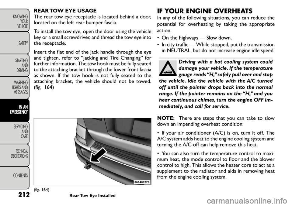
REAR TOW EYE USAGE
The rear tow eye receptacle is located behind a door,
located on the left rear bumper fascia.
To install the tow eye, open the door using the vehicle
key or a small screwdriver, and thread the tow eye into
the receptacle.
Insert the flat end of the jack handle through the eye
and tighten, refer to “Jacking and Tire Changing” for
further information. The tow hook must be fully seated
to the attaching bracket through the lower front fascia
as shown. If the tow hook is not fully seated to the
attaching bracket, the vehicle should not be towed.
(fig. 164)IF YOUR ENGINE OVERHEATS
In any of the following situations, you can reduce the
potential for overheating by taking the appropriate
action.
• On the highways — Slow down.
• In city traffic — While stopped, put the transmission
in NEUTRAL, but do not increase engine idle speed.
Driving with a hot cooling system could
damage your vehicle. If the temperature
gauge reads “H,” safely pull over and stop
the vehicle. Idle the vehicle with the A/C turned
off until the pointer drops back into the normal
range. If the pointer remains on the “H,” and you
hear continuous chimes, turn the engine OFF im-
mediately, and call for service.
NOTE: There are steps that you can take to slow
down an impending overheat condition:
• If your air conditioner (A/C) is on, turn it off. The
A/C system adds heat to the engine cooling system and
turning the A/C off can help remove this heat.
• You can also turn the temperature control to maxi-
mum heat, the mode control to floor and the blower
control to high. This allows the heater core to act as a
supplement to the radiator and aids in removing heat
from the engine cooling system.
(fig. 164) Rear Tow Eye Installed
212
KNOWING
YOUR
VEHICLE
SAFETY
STARTING AND
DRIVING
WARNING
LIGHTS AND
MESSAGES
IN AN
EMERGENCY
SERVICING AND
CARETECHNICAL
SPECIFICATIONSCONTENTS
Page 226 of 267
MAINTENANCE PROCEDURES
The pages that follow contain therequiredmainte-
nance services determined by the engineers who de-
signed your vehicle.
Besides those maintenance items specified in the fixed
maintenance schedule, there are other components
which may require servicing or replacement in the
future.
Failure to properly maintain your ve-
hicle or perform repairs and service when
necessary could result in more costly re-
pairs, damage to other components or negatively
impact vehicle performance. Immediately have
potential malfunctions examined by an autho-
rized dealership or qualified repair center.
Your vehicle has been built with improved fluids
that protect the performance and durability of
your vehicle and also allow extended mainte-
nance intervals. Do not use chemical flushes in
these components as the chemicals can damage
your engine, transmission, power steering or air
conditioning. Such damage is not covered by the
New Vehicle Limited Warranty. If a flush is needed
because of component malfunction, use only the
specified fluid for the flushing procedure. ENGINE OIL
Checking Oil Level – 2.0L Diesel Engine
To assure proper engine lubrication, the engine oil
must be maintained at the correct level. Check the oil
level at regular intervals, such as every fuel stop.
The best time to check the engine oil level is about five
minutes after a fully warmed engine is shut off or
before starting the engine after it has sat overnight.
Checking the oil while the vehicle is on level ground will
improve the accuracy of the oil level readings. Maintain
the oil level between the MIN and MAX markings on
the dipstick. Adding 1.0 qt (1.0 l) of oil when the
reading is at the MIN mark will result in a MAX reading
on these engines.
Change Engine Oil – 2.0L Diesel Engine
Refer to the “Maintenance Schedule” for the proper
maintenance intervals.
Engine Oil Viscosity – 2.0L Diesel Engine
For best performance and maximum protection under
all types of operating conditions, the manufacturer
recommends Fully Synthetic Low Ash 5W-30 engine
oils that meet the requirements of FIAT 9.55535-S1
spec and ACEA C1/C2.
Materials Added To Engine Oil
Do not add any supplemental materials, other than leak
detection dyes, to the engine oil. Engine oil is an
engineered product and its performance may be im-
paired by supplemental additives.
219
KNOWING
YOURVEHICLE SAFETY
STARTING ANDDRIVING
WARNING
LIGHTS AND
MESSAGES
IN AN
EMERGENCYSERVICING AND
CARETECHNICAL
SPECIFICATIONSCONTENTS
Page 228 of 267
It is essential when replacing the cables
on the battery that the positive cable is
attached to the positive post and the
negative cable is attached to the negative post .
Battery posts are marked positive (+) and nega-
tive (-) and identified on the battery case. Cable
clamps should be tight on the terminal posts and
free of corrosion.
If a “fast charger ” is used while the battery is in
the vehicle, disconnect both vehicle battery cables
before connecting the charger to the battery. Do
not use a “fast charger ” to provide starting volt-
age as battery damage can result .
AIR CONDITIONER MAINTENANCE
For best possible performance, your air conditioner
should be checked and serviced by an authorized
dealer at the start of each warm season. This service
should include cleaning of the condenser fins and a
performance test. Drive belt tension should also be
checked at this time.Do not use chemical flushes in your air
conditioning system as the chemicals can
damage your air conditioning compo-
nents. Such damage is not covered by the New
Vehicle Limited Warranty.
WARNING!
Use only refrigerants and compressor
lubricants approved by the manufac-
turer for your air conditioning system. Some un-
approved refrigerants are flammable and can
explode, injuring you. Other unapproved refrig-
erants or lubricants can cause the system to fail,
requiring costly repairs.
The air conditioning system contains refriger-
ant under high pressure.To avoid risk of personal
injury or damage to the system, adding refriger-
ant or any repair requiring lines to be discon-
nected should be done by an experienced
technician.
Refrigerant Recovery And Recycling
R-134a Air Conditioning Refrigerant is a hydrofluoro-
carbon (HFC) that is endorsed by the Environmental
Protection Agency and is an ozone-saving product.
However, the manufacturer recommends that air con-
ditioning service be performed by authorized dealers
or other service facilities using recovery and recyclingequipment.
NOTE: Use only manufacturer approved A/C system
sealers, stop leak products, seal conditioners, com-
pressor oil, and refrigerants.
A/C AIR FILTER — IF EQUIPPED
Refer to the “Maintenance Schedule” for the proper
maintenance intervals. 221
KNOWING
YOURVEHICLE SAFETY
STARTING ANDDRIVING
WARNING
LIGHTS AND
MESSAGES
IN AN
EMERGENCYSERVICING AND
CARETECHNICAL
SPECIFICATIONSCONTENTS
Page 232 of 267
rating information can be found on most washer fluid
containers.
The fluid reservoir will hold nearly 4 Liters of washer
fluid when the message “LoWASH” appears in the
instrument cluster.
WARNING!
Commercially available windshield
washer solvents are flammable. They
could ignite and burn you. Care must be exer-
cised when filling or working around the washer
solution.
EXHAUST SYSTEM
The best protection against carbon monoxide entry
into the vehicle body is a properly maintained engine
exhaust system.
Whenever a change is noticed in the sound of the
exhaust system, when exhaust fumes can be detected
inside the vehicle, or when the underside or rear of the
vehicle is damaged, have a competent technician in-
spect the complete exhaust system and adjacent body
areas for broken, damaged, deteriorated, or misposi-
tioned parts. Open seams or loose connections could
permit exhaust fumes to seep into the passenger com-
partment. In addition, inspect the exhaust system each
time the vehicle is raised for lubrication or oil change.
Replace as required.
WARNING!
Exhaust gases can injure or kill. They
contain carbon monoxide (CO), which is
colorless and odorless. Breathing it can make you
unconscious and can eventually poison you. To
avoid breathing CO, refer to “Safety Tips/Exhaust
Gas” in “Safety” for further information.
NOTE: Intentional tampering with emissions control
systems can result in civil penalties being assessed
against you.
WARNING!
A hot exhaust system can start a fire if
you park over materials that can burn.
Such materials might be grass or leaves coming
into contact with your exhaust system. Do not
park or operate your vehicle in areas where your
exhaust system can contact anything that canburn.
In unusual situations involving grossly malfunctioning
engine operation, a scorching odor may indicate severe
and abnormal catalyst overheating. If this occurs, safely
bring the vehicle to a complete stop, shut the engine
OFF, and allow the vehicle to cool. Thereafter, obtain
service, including a tune-up to manufacturer's specifi-
cations immediately.
225
KNOWING
YOURVEHICLE SAFETY
STARTING ANDDRIVING
WARNING
LIGHTS AND
MESSAGES
IN AN
EMERGENCYSERVICING AND
CARETECHNICAL
SPECIFICATIONSCONTENTS
Page 235 of 267
Coolant Level
The radiator normally remains completely full, so there
is no need to remove the radiator cap unless checking
for coolant freeze point or replacing coolant. Advise
your service attendant of this. As long as the engine
operating temperature is satisfactory, the coolant
bottle need only be checked once a month. When
additional coolant is needed to maintain the proper
level, it should be added to the coolant bottle. Do not
overfill.
Points To Remember
NOTE:When the vehicle is stopped after a few miles
(kilometers) of operation, you may observe vapor
coming from the front of the engine compartment.
This is normally a result of moisture from rain, snow, or
high humidity accumulating on the radiator and being
vaporized when the thermostat opens, allowing hot
coolant to enter the radiator.
If an examination of your engine compartment shows
no evidence of radiator or hose leaks, the vehicle may
be safely driven. The vapor will soon dissipate.
• Do not overfill the coolant recovery bottle.
• Check coolant freeze point in the radiator and in the coolant recovery bottle. If antifreeze needs to be
added, contents of coolant recovery bottle must also
be protected against freezing.
• If frequent coolant additions are required, or if the level in the coolant recovery bottle does not drop
when the engine cools, the cooling system should be
pressure tested for leaks. • Make sure that the radiator and coolant recovery
bottle overflow hoses are not kinked or obstructed.
• Keep the front of the radiator clean. If your vehicle is equipped with air conditioning, keep the front of the
condenser clean.
• Do not change the thermostat for Summer or Win- ter operation. If replacement is ever necessary, install
ONLY the correct type thermostat. Other designs
may result in unsatisfactory coolant performance,
poor gas mileage, and increased emissions.
BRAKE SYSTEM
In order to assure brake system performance, all brake
system components should be inspected periodically.
Refer to the “Maintenance Schedule” for the proper
maintenance intervals.
WARNING!
Riding the brakes can lead to brake fail-
ure and possibly an accident . Driving
with your foot resting or riding on the brake
pedal can result in abnormally high brake tem-
peratures, excessive lining wear, and possible
brake damage.You would not have your full brak-
ing capacity in an emergency.
Master Cylinder – Brake Fluid Level Check
Check the fluid level in the master cylinder immediately
if the “Brake Warning Light” indicates system failure.
Check the fluid level in the master cylinder when
performing underhood services.
228
KNOWING
YOUR
VEHICLE
SAFETY
STARTING AND
DRIVING
WARNING
LIGHTS AND
MESSAGES
IN AN
EMERGENCYSERVICING AND
CARETECHNICAL
SPECIFICATIONSCONTENTS
Page 245 of 267

LIMITED-USE SPARE – IF EQUIPPED
The limited-use spare tire is for temporary emergency
use only. This tire is identified by a label located on the
limited-use spare wheel. This label contains the driving
limitations for this spare. This tire may look like the
original equipped tire on the front or rear axle of your
vehicle, but it is not. Installation of this limited-use
spare tire affects vehicle handling. Since it is not the
same as your original equipment tire, replace (or re-
pair) the original equipment tire and reinstall on the
vehicle at the first opportunity.
WARNING!
Limited-use spares are for emergency
use only. Installation of this limited-use
spare tire affects vehicle handling.With this tire,
do not drive more than the speed listed on the
limit-use spare wheel. Keep inflated to the cold
tire inflation pressure listed on your Tire and
Loading Information Placard located on the driv-
er ’s side door opening. Replace (or repair) the
original equipment tire at the first opportunity
and reinstall it on your vehicle. Failure to do so
could result in loss of vehicle control.
TIRE SPINNING
When stuck in mud, sand, snow, or icy conditions, do
not spin your vehicle's wheels faster than 30 mph
(48 km/h) or for longer than 30 seconds continuously
without stopping. Refer to “Freeing A Stuck Vehicle” in “In An Emer-
gency” for further information.
WARNING!
Fast spinning tires can be dangerous.
Forces generated by excessive wheel
speeds may cause tire damage or failure. A tire
could explode and injure someone. Do not spin
your vehicle's wheels faster than 48 km/h or for
more than 30 seconds continuously when you are
stuck, and do not let anyone near a spinning
wheel, no matter what the speed.
TREAD WEAR INDICATORS
Tread wear indicators are in the original equipment
tires to help you in determining when your tires should
be replaced. (fig. 172)
These indicators are molded into the bottom of the
tread grooves. They will appear as bands when the
tread depth becomes 2 mm. When the tread is worn to
the tread wear indicators, the tire should be replaced.
LIFE OF TIRE
The service life of a tire is dependent upon varying
factors including but not limited to:
• Driving style
• Tire pressure
• Distance driven
238
KNOWING YOUR
VEHICLE
SAFETY
STARTING AND
DRIVING
WARNING
LIGHTS AND
MESSAGES
IN AN
EMERGENCY
SERVICING AND
CARETECHNICAL
SPECIFICATIONSCONTENTS