window FIAT FREEMONT 2011 Owner handbook (in English)
[x] Cancel search | Manufacturer: FIAT, Model Year: 2011, Model line: FREEMONT, Model: FIAT FREEMONT 2011Pages: 267, PDF Size: 5.16 MB
Page 13 of 267
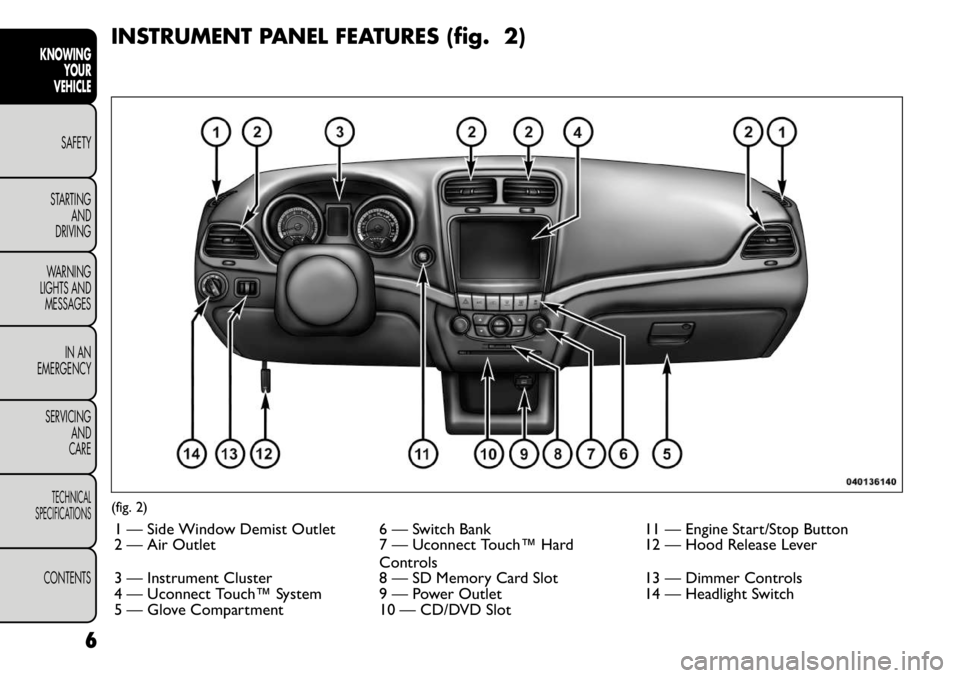
INSTRUMENT PANEL FEATURES (fig. 2)(fig. 2)1 — Side Window Demist Outlet 6 — Switch Bank 11 — Engine Start/Stop Button
2 — Air Outlet 7 — Uconnect Touch™ Hard Controls12 — Hood Release Lever
3 — Instrument Cluster 8 — SD Memory Card Slot 13 — Dimmer Controls
4 — Uconnect Touch™ System 9 — Power Outlet 14 — Headlight Switch
5 — Glove Compartment 10 — CD/DVD Slot
6
KNOWING YOUR
VEHICLE
SAFETY
STARTING AND
DRIVING
WARNING
LIGHTS AND
MESSAGES
IN AN
EMERGENCY
SERVICING AND
CARETECHNICAL
SPECIFICATIONSCONTENTS
Page 16 of 267
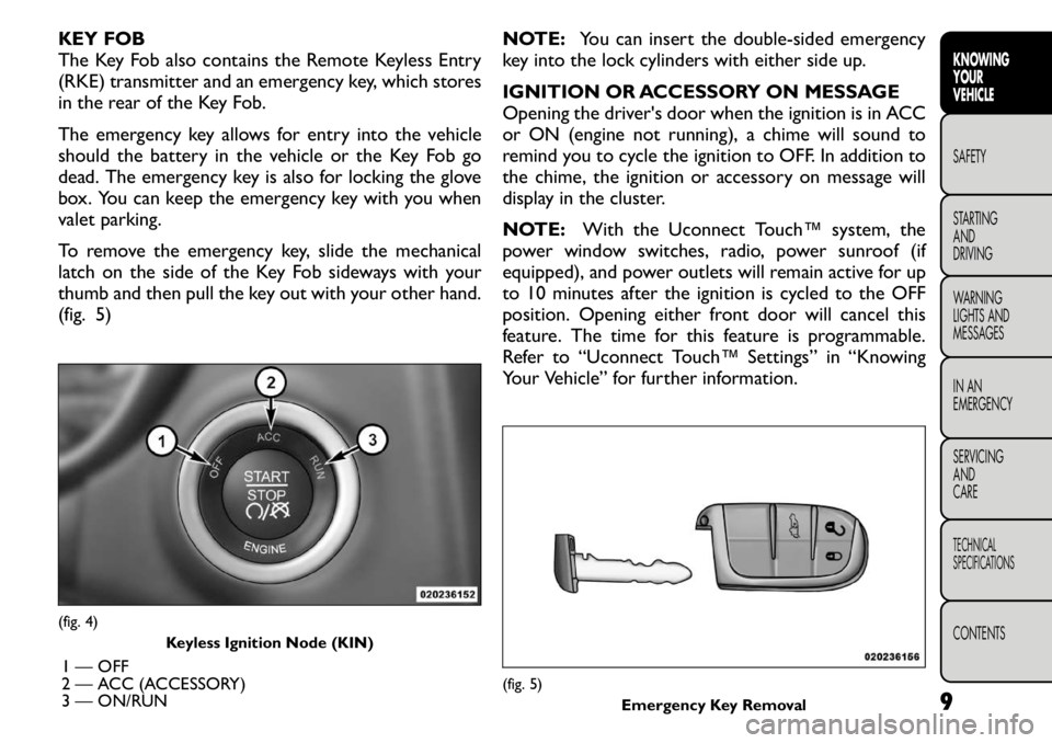
KEY FOB
The Key Fob also contains the Remote Keyless Entry
(RKE) transmitter and an emergency key, which stores
in the rear of the Key Fob.
The emergency key allows for entry into the vehicle
should the battery in the vehicle or the Key Fob go
dead. The emergency key is also for locking the glove
box. You can keep the emergency key with you when
valet parking.
To remove the emergency key, slide the mechanical
latch on the side of the Key Fob sideways with your
thumb and then pull the key out with your other hand.
(fig. 5)NOTE:
You can insert the double-sided emergency
key into the lock cylinders with either side up.
IGNITION OR ACCESSORY ON MESSAGE
Opening the driver's door when the ignition is in ACC
or ON (engine not running), a chime will sound to
remind you to cycle the ignition to OFF. In addition to
the chime, the ignition or accessory on message will
display in the cluster.
NOTE: With the Uconnect Touch™ system, the
power window switches, radio, power sunroof (if
equipped), and power outlets will remain active for up
to 10 minutes after the ignition is cycled to the OFF
position. Opening either front door will cancel this
feature. The time for this feature is programmable.
Refer to “Uconnect Touch™ Settings” in “Knowing
Your Vehicle” for further information.(fig. 4) Keyless Ignition Node (KIN)
1 — OFF
2 — ACC (ACCESSORY)
3 — ON/RUN
(fig. 5) Emergency Key Removal 9
KNOWING
YOURVEHICLESAFETY
STARTING ANDDRIVING
WARNING
LIGHTS AND
MESSAGES
IN AN
EMERGENCY
SERVICING AND
CARETECHNICAL
SPECIFICATIONSCONTENTS
Page 17 of 267
WARNING!
Before exiting a vehicle, always apply
the parking brake, shift the transmission
into PARK, and remove the key fob from the
ignition. When leaving the vehicle, always lock
your vehicle.
Never leave children alone in a vehicle, or with
access to an unlocked vehicle.
Allowing children to be in a vehicle unattended
is dangerous for a number of reasons. A child or
others could be seriously or fatally injured. Chil-
dren should be warned not to touch the parking
brake, brake pedal or the shift lever.
Do not leave the key fob in or near the vehicle,
and do not leave Keyless Enter-N-Go in the ACC
or ON/RUN mode. A child could operate power
windows, other controls, or move the vehicle.
Do not leave children or animals inside parked
vehicles in hot weather. Interior heat build-up
may cause serious injury or death.An unlocked car is an invitation to
thieves. Always remove the Key Fob from
vehicle, cycle the ignition OFF and lock
all doors when leaving the vehicle unattended. SENTRY KEY®
The Sentry Key
®Immobilizer system prevents unau-
thorized vehicle operation by disabling the engine. The
system does not need to be armed or activated. Op-
eration is automatic, regardless of whether the vehicle
is locked or unlocked.
The system uses a Key Fob with Remote Keyless Entry
(RKE) transmitter, a Keyless Ignition Node (KIN) and a
RF receiver to prevent unauthorized vehicle operation.
Therefore, only Key Fobs that are programmed to the
vehicle can be used to start and operate the vehicle.
After cycling the ignition to the ON/RUN position, the
Vehicle Security Light will turn on for three seconds for
a bulb check. If the light remains on after the bulb
check, it indicates that there is a problem with the
electronics. In addition, if the light begins to flash after
the bulb check, it indicates that someone used an
invalid Key Fob to start the engine. Either of these
conditions will result in the engine being shut off after
two seconds.
If the Vehicle Security Light turns on during normal
vehicle operation (vehicle running for longer than
10 seconds), it indicates that there is a fault in the
electronics. Should this occur, have the vehicle serviced
as soon as possible by an authorized dealer.
10
KNOWING YOUR
VEHICLE
SAFETY
STARTING AND
DRIVING
WARNING
LIGHTS AND
MESSAGES
IN AN
EMERGENCY
SERVICING AND
CARETECHNICAL
SPECIFICATIONSCONTENTS
Page 20 of 267
If the vehicle is equipped with Passive Entry, refer to
“Keyless Enter-N-Go — If Equipped” under “Knowing
Your Vehicle” for further information.
REMOTE OPEN WINDOW FEATURE
This feature allows you to remotely lower both front
door windows at the same time. To use this feature,
press and release the UNLOCK button on the RKE
transmitter and then immediately press and hold the
UNLOCK button until the windows lower to the level
desired or until they lower completely.
PROGRAMMING ADDITIONAL TRANSMITTERS
Programming Key Fobs or RKE transmitters may be
performed at an authorized dealer.
TRANSMITTER BATTERY REPLACEMENT
The recommended replacement battery is one
CR2032 battery.
NOTE:
• Perchlorate Material — special handling may apply.
• Used batteries are harmful to the environment. You
can dispose of them either in the correct containers as
specified by law or by taking them to a FIAT Dealership,
which will deal with their disposal.
• Do not touch the battery terminals that are on the
back housing or the printed circuit board.
1. Remove the emergency key by sliding the mechani-cal latch on the back of the RKE transmitter side-
ways with your thumb and then pull the key out with
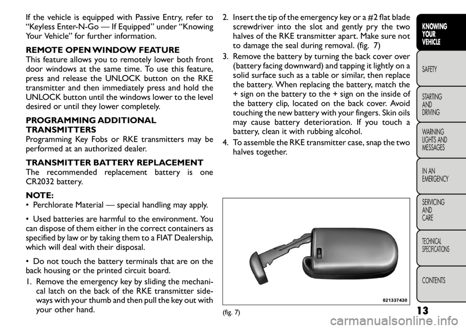
your other hand. 2. Insert the tip of the emergency key or a #2 flat blade
screwdriver into the slot and gently pry the two
halves of the RKE transmitter apart. Make sure not
to damage the seal during removal. (fig. 7)
3. Remove the battery by turning the back cover over (battery facing downward) and tapping it lightly on a
solid surface such as a table or similar, then replace
the battery. When replacing the battery, match the
+ sign on the battery to the + sign on the inside of
the battery clip, located on the back cover. Avoid
touching the new battery with your fingers. Skin oils
may cause battery deterioration. If you touch a
battery, clean it with rubbing alcohol.
4. To assemble the RKE transmitter case, snap the two halves together.
(fig. 7) 13
KNOWING
YOURVEHICLESAFETY
STARTING ANDDRIVING
WARNING
LIGHTS AND
MESSAGES
IN AN
EMERGENCY
SERVICING AND
CARETECHNICAL
SPECIFICATIONSCONTENTS
Page 36 of 267

NOTE:If the vehicle is equipped with Keyless Enter-
N-Go (Passive Entry) and the EVIC is programmed to
Unlock All Doors 1st Press, all doors will unlock no
matter which Passive Entry equipped door handle is
grasped. If Driver Door 1st Press is programmed, only
the driver’s door will unlock when the driver’s door is
grasped. With Passive Entry, if Driver Door 1st Press is
programmed touching the handle more than once will
only result in the driver’s door opening. If driver door
first is selected, once the driver door is opened, the
interior door lock/unlock switch can be used to unlock
all doors (or use RKE transmitter).
Passive Entry (Keyless Enter-N-Go)
Press the Passive Entry soft-key to change this display.
This feature allows you to lock and unlock the vehicle’s
door(s) without having to press the RKE transmitter
lock or unlock buttons. To make your selection, press
the Passive Entry soft-key, select ON or OFF followed
by pressing the arrow back soft-key. Refer to “Keyless
Enter-N-Go” in “Knowing Your Vehicle”.
Heated Seats
Auto Heated Seats
Press the Auto Heated Seats soft-key to change this
display. When this feature is selected the driver's
heated seat will automatically turn on when tempera-
tures are below 4.4° C. To make your selection, press
the Auto Heated Seats soft-key, select On or Off
followed by pressing the arrow back soft-key. Engine Off Options
Easy Exit Seats
Press the Easy Exit Seats soft-key to change this display.
This feature provides automatic driver seat positioning
to enhance driver mobility when entering and exiting
the vehicle. To make your selection, press the Easy Exit
Seats soft-key, select On or Off followed by pressing
the arrow back soft-key.
NOTE:
The seat will return to the memorized seat
location (if Recall Memory with Remote Key Unlock is
set to ON) when the RKE transmitter is used to unlock
the door.
Headlight Off Delay
Press the Headlight Off Delay soft-key to change this
display. When this feature is selected, the driver can
choose to have the headlights remain on for 0, 30, 60,
or 90 seconds when exiting the vehicle. To change the
Headlight Off Delay status press the 0, 30, 60 or 90
soft-key followed by pressing the arrow back soft-key.
Engine Off Power Delay
Press the Engine Off Power Delay soft-key to change
this display. When this feature is selected, the power
window switches, radio, Uconnect™ phone system (if
equipped), DVD video system (if equipped), power
sunroof (if equipped), and power outlets will remain
active for up to 10 minutes after the ignition is cycled to
OFF. Opening either front vehicle door will cancel this
feature. To change the Engine Off Power Delay status
29
KNOWING
YOURVEHICLESAFETY
STARTING ANDDRIVING
WARNING
LIGHTS AND
MESSAGES
IN AN
EMERGENCY
SERVICING AND
CARETECHNICAL
SPECIFICATIONSCONTENTS
Page 43 of 267

Engine Off Options
Easy Exit Seat
This feature provides automatic driver seat positioning
to enhance driver mobility when entering and exiting
the vehicle. To make your selection, press the Easy Exit
Seats soft-key, select On or Off followed by pressing
the arrow back soft-key.
Engine Off Power Delay
When this feature is selected, the power window
switches, radio, Uconnect™ phone system (if
equipped), DVD video system (if equipped), power
sunroof (if equipped), and power outlets will remain
active for up to 10 minutes after the ignition is cycled
OFF. Opening either front vehicle door will cancel this
feature. To change the Engine Off Power Delay status
press the 0 seconds, 45 seconds, 5 minutes or 10 min-
utes soft-key followed by pressing the arrow back
soft-key.
Headlight Off Delay
When this feature is selected, the driver can choose to
have the headlights remain on for 0, 30, 60, or 90 sec-
onds when exiting the vehicle. To change the Headlight
Off Delay status press the 0, 30, 60 or 90 soft-key
followed by pressing the arrow back soft-key.Compass Settings
Variance
Compass Variance is the difference between Magnetic
North and Geographic North. To compensate for the
differences the variance should be set for the zone
where the vehicle is driven, per the zone map. Once
properly set, the compass will automatically compen-
sate for the differences, and provide the most accurate
compass heading.
NOTE:
Keep magnetic materials away from the top
of the instrument panel, such as iPod's, Mobile Phones,
Laptops and Radar Detectors. This is where the com-
pass module is located, and it can cause interference
with the compass sensor, and it may give false readings.
(fig. 15)
36
KNOWING YOUR
VEHICLE
SAFETY
STARTING AND
DRIVING
WARNING
LIGHTS AND
MESSAGES
IN AN
EMERGENCY
SERVICING AND
CARETECHNICAL
SPECIFICATIONSCONTENTS
Page 60 of 267
WARNING!
Do not adjust the steering column while
driving. Adjusting the steering column
while driving or driving with the steering column
unlocked could cause the driver to lose control of
the vehicle. Be sure the steering column is locked
before driving your vehicle. Failure to follow this
warning may result in serious injury or death. MIRRORS
INSIDE DAY/NIGHT MIRROR
A single ball joint mirror is provided in the vehicle. It is
a twist on mirror that has a fixed position. The mirror
installs on the windshield button with a counterclock-
wise rotation and requires no tools for mounting.
The mirror head can be adjusted up, down, left, and
right for various drivers. The mirror should be adjusted
to center on the view through the rear window.
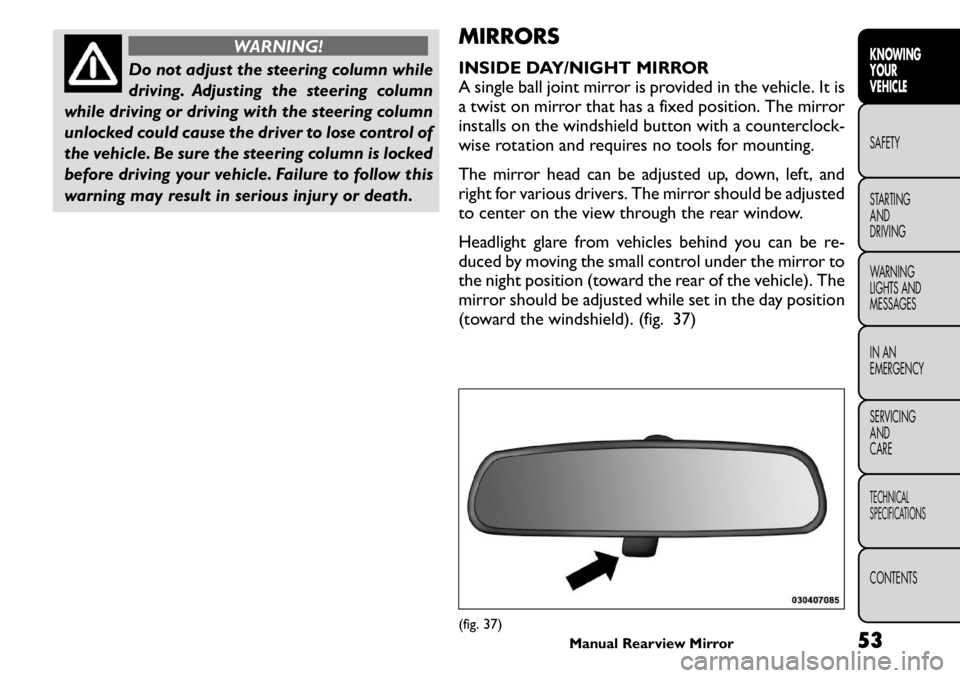
Headlight glare from vehicles behind you can be re-
duced by moving the small control under the mirror to
the night position (toward the rear of the vehicle). The
mirror should be adjusted while set in the day position
(toward the windshield). (fig. 37)
(fig. 37)
Manual Rearview Mirror 53
KNOWING
YOURVEHICLESAFETY
STARTING ANDDRIVING
WARNING
LIGHTS AND
MESSAGES
IN AN
EMERGENCY
SERVICING AND
CARETECHNICAL
SPECIFICATIONSCONTENTS
Page 61 of 267
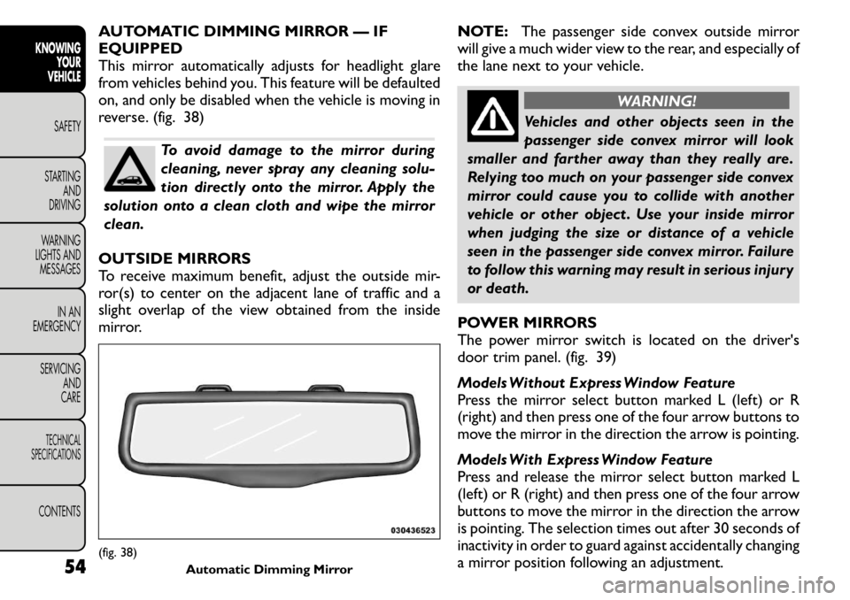
AUTOMATIC DIMMING MIRROR — IF EQUIPPED
This mirror automatically adjusts for headlight glare
from vehicles behind you. This feature will be defaulted
on, and only be disabled when the vehicle is moving in
reverse. (fig. 38)
To avoid damage to the mirror during
cleaning, never spray any cleaning solu-
tion directly onto the mirror. Apply the
solution onto a clean cloth and wipe the mirrorclean.
OUTSIDE MIRRORS
To receive maximum benefit, adjust the outside mir-
ror(s) to center on the adjacent lane of traffic and a
slight overlap of the view obtained from the inside
mirror. NOTE:
The passenger side convex outside mirror
will give a much wider view to the rear, and especially of
the lane next to your vehicle.
WARNING!
Vehicles and other objects seen in the
passenger side convex mirror will look
smaller and farther away than they really are.
Relying too much on your passenger side convex
mirror could cause you to collide with another
vehicle or other object . Use your inside mirror
when judging the size or distance of a vehicle
seen in the passenger side convex mirror. Failure
to follow this warning may result in serious injury
or death.
POWER MIRRORS
The power mirror switch is located on the driver's
door trim panel. (fig. 39)
Models Without Express Window Feature
Press the mirror select button marked L (left) or R
(right) and then press one of the four arrow buttons to
move the mirror in the direction the arrow is pointing.
Models With Express Window Feature
Press and release the mirror select button marked L
(left) or R (right) and then press one of the four arrow
buttons to move the mirror in the direction the arrow
is pointing. The selection times out after 30 seconds of
inactivity in order to guard against accidentally changing
a mirror position following an adjustment.
(fig. 38) Automatic Dimming Mirror
54
KNOWING
YOUR
VEHICLE
SAFETY
STARTING AND
DRIVING
WARNING
LIGHTS AND
MESSAGES
IN AN
EMERGENCY
SERVICING AND
CARETECHNICAL
SPECIFICATIONSCONTENTS
Page 62 of 267

NOTE:A light in the selected button will illuminate
indicating the mirror is activated and can be adjusted.
POWER FOLDING MIRRORS — IF EQUIPPED
The switch for the power folding mirrors is located
between the power mirror switches L (left) and R
(right). Press the switch once and the mirrors will fold
in, pressing the switch a second time will return the
mirrors to the normal driving position.
NOTE: Pressing the power folding mirror switch for
more than four seconds, or if the vehicle speed is
greater than 8 km/h will disable the folding feature.
If the mirrors are in the folded position, and vehicle
speed is equal or greater than 8 km/h, they will auto-
matically unfold. MANUAL FOLDING MIRRORS — IFEQUIPPED
Some models have exterior mirrors that are hinged.
The hinge allows the mirror to pivot forward and
rearward to resist damage. The hinge has three detent
positions: forward, rearward and normal.
HEATED MIRRORS — IF EQUIPPED
These mirrors are heated to melt frost or ice.
This feature is activated whenever you turn on
the rear window defroster. Refer to “Rear Window
Features” for further information.
ILLUMINATED VANITY MIRRORS — IF EQUIPPED
An illuminated vanity mirror is on each sun visor. To use
the mirror, rotate the sun visor downward and swing
the mirror cover upward. The light will turn on auto-
matically. Closing the mirror cover will turn off the
light. (fig. 40)
Sun Visor “Slide-On Rod” Feature — If
Equipped
This feature allows for additional flexibility in position-
ing the visor to block out the sun.
1. Fold down the sun visor.
2. Unclip the visor from the center clip.
3. Pull the sun visor toward the inside rearview mirror
to extend it.(fig. 39) Power Mirror Switches
55KNOWING
YOURVEHICLESAFETY
STARTING ANDDRIVING
WARNING
LIGHTS AND
MESSAGES
IN AN
EMERGENCY
SERVICING AND
CARETECHNICAL
SPECIFICATIONSCONTENTS
Page 65 of 267
equipped with ATC. The speeds can be selected using
either hard-heys or soft-keys as follows:
Hard-Keys
The blower speed increases as you turn the control
clockwise from the lowest blower setting. The blower
speed decreases as you turn the knob counter-
clockwise.
Soft-Key — Uconnect Touch™ System 4.3
Press the blower soft-key to enter the blower setting
screen. Once in the blower setting screen, use the UP
and DOWN arrows to adjust the blower speed setting,
or directly select the speed setting by pressing the
blower bar area around the blower icon. The blower
speed increases as you press the UP arrow or move
clockwise on the setting scale and decreases when you
press the DOWN arrow or move counter-clockwise
on the setting scale.
Soft-Key — Uconnect Touch™ System 8.4
Use the small blower icon to reduce the blower setting
and the large blower icon to increase the blower
setting. Blower can also be selected by pressing the
blower bar area between the icons.
4. Front Defrost Button
Press and release to change the current airflow setting
to Defrost mode. The indicator illuminates when this
feature is ON. Performing this function will cause the
ATC (if equipped) to switch into manual mode. The
blower speed may increase when Defrost mode is
selected. If the front defrost mode is turned off, the
climate system will return the previous setting.5. Rear Defrost Button
Press and release this button to turn on the rear
window defroster and the heated outside mirrors (if
equipped). An indicator will illuminate when the rear
window defroster is on. The rear window defroster
automatically turns off after 10 minutes.
Failure to follow these cautions can
cause damage to the heating elements:
Use care when washing the inside of
the rear window. Do not use abrasive window
cleaners on the interior surface of the window.
Use a soft cloth and a mild washing solution,
wiping parallel to the heating elements. Labels
can be peeled off after soaking with warm water.
Do not use scrapers, sharp instruments, or abra-
sive window cleaners on the interior surface of
the window.
Keep all objects a safe distance from the
window.
6. Passenger Temperature Control Up Button
Provides the passenger with independent temperature
control. Push the button for warmer temperaturesettings.
NOTE: Pressing this button while in Sync mode will
automatically exit Sync.
58
KNOWING YOUR
VEHICLE
SAFETY
STARTING AND
DRIVING
WARNING
LIGHTS AND
MESSAGES
IN AN
EMERGENCY
SERVICING AND
CARETECHNICAL
SPECIFICATIONSCONTENTS