ESP FIAT FREEMONT 2012 Owner handbook (in English)
[x] Cancel search | Manufacturer: FIAT, Model Year: 2012, Model line: FREEMONT, Model: FIAT FREEMONT 2012Pages: 332, PDF Size: 5.61 MB
Page 8 of 332

IMPORTANT NOTICE
ALL MATERIAL CONTAINED IN THIS PUBLICA-
TION IS BASED ON THE LATEST INFORMATION
AVAILABLE AT TIME OF PUBLICATION APPROVAL.
THE RIGHT IS RESERVED TO PUBLISH REVISIONS
AT ANY TIME.
This Owner's Manual has been prepared with the
assistance of service and engineering specialists to
acquaint you with the operation and maintenance of
your new vehicle. It is supplemented by a Warranty
Information Booklet and various customer-oriented
documents. You are urged to read these publications
carefully. Following the instructions and recommenda-
tions in this Owner's Manual will help assure safe and
enjoyable operation of your vehicle.
After you have read the Owner’s Manual, it should be
stored in the vehicle for convenient reference and
remain with the vehicle when sold.
The manufacturer reserves the right to make changes
in design and specifications, and/or to make additions
to or improvements in its products without imposing
any obligations upon itself to install them on products
previously manufactured.
The Owner's Manual illustrates and describes the fea-
tures that are standard or available as extra cost op-
tions. Therefore, some of the equipment and accesso-
ries in this publication may not appear on your vehicle.NOTE:
Be sure to read the Owner's Manual first
before driving your vehicle and before attaching or
installing parts/accessories or making other modifica-
tions to the vehicle.
In view of the many replacement parts and accessories
from various manufacturers available on the market,
the manufacturer cannot be certain that the driving
safety of your vehicle will not be impaired by the
attachment or installation of such parts. Even if such
parts are officially-approved (for example, by a general
operating permit for the part or by constructing the
part in an officially approved design), or if an individual
operating permit was issued for the vehicle after the
attachment or installation of such parts, it cannot be
implicitly assumed that the driving safety of your ve-
hicle is unimpaired. Therefore, neither experts nor
official agencies are liable. The manufacturer only as-
sumes responsibility when parts, which are expressly
authorized or recommended by the manufacturer, are
attached or installed at an authorized dealer. The same
applies when modifications to the original condition
are subsequently made on the manufacturer's vehicles.
Your warranties do not cover any part that the manu-
facturer did not supply. Nor do they cover the cost of
any repairs or adjustments that might be caused or
needed because of the installation or use of non-
manufacturer parts, components, equipment, materi-
als, or additives. Nor do your warranties cover the
costs of repairing damage or conditions caused by any
2
KNOWING YOUR
VEHICLE
SAFETY
STARTING AND
DRIVING
WARNING LIGHTSAND
MESSAGES
IN AN
EMERGENCY
SERVICING AND
CARETECHNICAL
SPECIFICATIONSCONTENTS
Page 18 of 332
NOTE:When having the Sentry Key
®Immobilizer
system serviced, bring all vehicle Key Fobs with you to
the authorized dealer.
CUSTOMER KEY PROGRAMMING
Programming Key Fobs or RKE transmitters may be
performed at an authorized dealer.
GENERAL INFORMATION
The Sentry Key
®Immobilizer system will be used in
the following European countries, which apply Direc-
tive 1999/5/EC: Austria, Belgium, Czech Republic,
Denmark, Finland, France, Germany, Greece, Hungary,
Ireland, Italy, Luxembourg, Netherlands, Norway, Po-
land, Portugal, Romania, Russian Federation, Slovenia,
Spain, Sweden, Switzerland, Yugoslavia, and UnitedKingdom.
Operation is subject to the following conditions:
• This device may not cause harmful interference.
• This device must accept any interference that may be received, including interference that may cause un-
desired operation. REMOTE KEYLESS ENTRY (RKE)
The RKE system allows you to lock or unlock the
doors and liftgate from distances up to approximately
10 m using a hand-held Key Fob with RKE transmitter.
The RKE transmitter does not need to be pointed at
the vehicle to activate the system.
NOTE:
Driving at speeds 8 km/h and above disables
the system from responding to all RKE transmitter
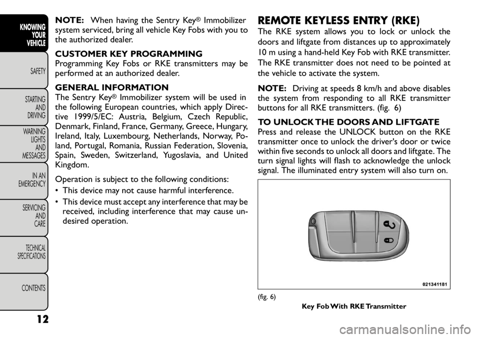
buttons for all RKE transmitters. (fig. 6)
TO UNLOCK THE DOORS AND LIFTGATE
Press and release the UNLOCK button on the RKE
transmitter once to unlock the driver's door or twice
within five seconds to unlock all doors and liftgate. The
turn signal lights will flash to acknowledge the unlock
signal. The illuminated entry system will also turn on.
(fig. 6)
Key Fob With RKE Transmitter
12
KNOWING YOUR
VEHICLE
SAFETY
STARTING AND
DRIVING
WARNING LIGHTSAND
MESSAGES
IN AN
EMERGENCY
SERVICING AND
CARETECHNICAL
SPECIFICATIONSCONTENTS
Page 19 of 332

If the vehicle is equipped with Passive Entry, refer to
“Keyless Enter-N-Go (for versions/markets, where
provided)” under “Knowing Your Vehicle” for further
information.
Remote Key Unlock, Driver Door/All Doors
1st Press
This feature lets you program the system to unlock
either the driver's door or all doors on the first press of
the UNLOCK button on the RKE transmitter. To
change the current setting, refer to “Uconnect
Touch™ Settings” in “Knowing Your Vehicle” for fur-
ther information.
Flash Headlights With Lock
This feature will cause the turn signal lights to flash
when the doors are locked or unlocked with the RKE
transmitter. This feature can be turned on or turned
off. To change the current setting, refer to “Uconnect
Touch™ Settings” in “Knowing Your Vehicle” for fur-
ther information.
Turn Headlights On With Remote Key Unlock
This feature activates the headlights for up to 90 sec-
onds when the doors are unlocked with the RKE
transmitter. The time for this feature is programmable
on vehicles equipped through Uconnect Touch™. To
change the current setting, refer to “Uconnect
Touch™ Settings” in “Knowing Your Vehicle” for fur-
ther information.TO LOCK THE DOORS AND LIFTGATE
Press and release the LOCK button on the RKE trans-
mitter to lock all doors and liftgate. The turn signal
lights will flash to acknowledge the signal.
If the vehicle is equipped with Passive Entry, refer to
“Keyless Enter-N-Go (for versions/markets, where
provided)” under “Knowing Your Vehicle” for further
information.
PROGRAMMING ADDITIONAL TRANSMITTERS
Programming Key Fobs or RKE transmitters may be
performed at an authorized dealer.
TRANSMITTER BATTERY REPLACEMENT
The recommended replacement battery is one
CR2032 battery.
NOTE:
• Perchlorate Material — special handling may apply.
Batteries could contain dangerous materials. Please
dispose of them according to respect for environment
and local laws.
• Used batteries are harmful to the environment. You
can dispose of them either in the correct containers as
specified by law or by taking them to a FIAT Dealership,
which will deal with their disposal.
• Do not touch the battery terminals that are on the
back housing or the printed circuit board.
13
KNOWING
YOURVEHICLESAFETY
STARTING ANDDRIVING
WARNING LIGHTSAND
MESSAGES
IN AN
EMERGENCY
SERVICING AND
CARETECHNICAL
SPECIFICATIONSCONTENTS
Page 34 of 332

Units (for versions/markets, where provided)
Press the Units soft-key to change this display. When in
this display you may select to have the EVIC, odometer,
and navigation system (for versions/markets, where
provided) changed between US and Metric units of
measure. Press US or Metric followed by pressing the
arrow back soft-key. Then, as you continue, the infor-
mation will display in the selected units of measure.
Voice Response (for versions/markets, whereprovided)
Press the Voice Response soft-key to change this dis-
play. When in this display you may change the Voice
Response Length settings. To change the Voice Re-
sponse Length press and release the Brief or Long
soft-key followed by pressing the arrow back soft-key.
Touch Screen Beep (for versions/markets, where provided)
Press the Touch Screen Beep soft-key to change this
display. When in this display you may turn on or shut off
the sound heard when a touch screen button (soft-key)
is pressed. To change the Touch Screen Beep setting
press and release the On or Off soft-key followed by
pressing the arrow back soft-key. Clock
Set Time (for versions/markets, where provided)
Press the Set Time soft-key to change this display.
When in this display you may select the time display
settings. To make your selection, press the Set Time soft-key, adjust the hours and minutes using the up and
down soft-keys, select AM or PM, select 12 hr or 24 hr
followed by pressing the arrow back soft-key when all
selections are complete.
Show Time Status (for versions/markets, where
provided)
Press the Show Time Status soft-key to change this
display. When in this display you may turn on or shut off
the digital clock in the status bar. To change the Show
Time Status setting press and release the On or Off
soft-key followed by pressing the arrow back soft-key.
Sync Time (for versions/markets, where provided)
Press the Sync Time soft-key to change this display.
When in this display you may automatically have the
radio set the time. To change the Sync Time setting
press and release the On or Off soft-key followed by
pressing the arrow back soft-key.
Safety / Assistance
Park Assist (for versions/markets, where provided)
Press the Park Assist soft-key to change this display.
The Rear Park Assist system will scan for objects
behind the vehicle when the transmission shift lever is
in REVERSE and the vehicle speed is less than 18 km/h.
The system can be enabled with Sound Only, Sound
and Display, or turned OFF. To change the Park Assist
status press and release the Off, Sound Only or Sounds
28
KNOWING YOUR
VEHICLE
SAFETY
STARTING AND
DRIVING
WARNING LIGHTSAND
MESSAGES
IN AN
EMERGENCY
SERVICING AND
CARETECHNICAL
SPECIFICATIONSCONTENTS
Page 40 of 332
release the Day, Night or Auto soft-key followed by
pressing the arrow back soft-key.
Display Brightness with Headlights ON (forversions/markets, where provided)
When in this display you may select display brightness
with the headlights on and the headlights off. Adjust the
brightness with the + and – setting soft-keys or by
selecting any point on the scale in between the + and –
soft-keys followed by pressing the arrow back soft-key.
Display Brightness with Headlights OFF (for versions/markets, where provided)
When in this display you may select display brightness
with the headlights on and the headlights off. Adjust the
brightness with the + and – setting soft-keys or by selecting any point on the scale in between the + and –
soft-keys followed by pressing the arrow back soft-key.
Set Language (for versions/markets, where
provided)
When in this display you may select a different language
for all display nomenclature, including the trip functions
and the navigation system (for versions/markets, where
provided). Press the German, French, Spanish, Italian,
Dutch or English button to select the language pre-
ferred followed by pressing the arrow back soft-key.
Then, as you continue, the information will display in
the selected language.
Units (for versions/markets, where provided)
When in this display you may select to have the EVIC,
odometer, and navigation system (for versions/
markets, where provided) changed between US and
Metric units of measure. Press US or Metric followed
by pressing the arrow back soft-key. Then, as you
continue, the information will display in the selected
units of measure.
Voice Response Length (for versions/markets, where provided)
When in this display you may change the Voice Re-
sponse Length settings. To change the Voice Response
Length press and release the Brief or Detailed soft-key
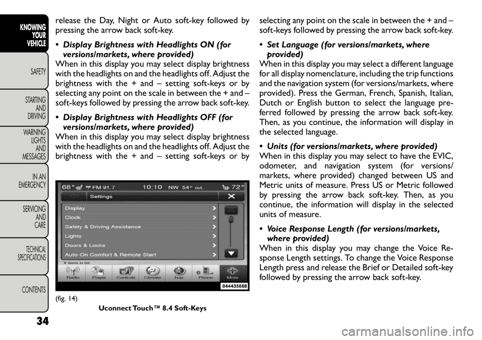
followed by pressing the arrow back soft-key.(fig. 14)
Uconnect Touch™ 8.4 Soft-Keys
34
KNOWING YOUR
VEHICLE
SAFETY
STARTING AND
DRIVING
WARNING LIGHTSAND
MESSAGES
IN AN
EMERGENCY
SERVICING AND
CARETECHNICAL
SPECIFICATIONSCONTENTS
Page 49 of 332
When the HI-level setting is selected, the heater will
provide a boosted heat level during the first four
minutes of operation. Then, the heat output will drop
to the normal HI-level. If the HI-level setting is se-
lected, the system will automatically switch to LO-level
after a maximum of 60 minutes of continuous opera-
tion. At that time, the display will change from HI to
LO, indicating the change. The LO-level setting will turn
OFF automatically after a maximum of 45 minutes.
WARNING!
Persons who are unable to feel pain to
the skin because of advanced age,
chronic illness, diabetes, spinal cord injury, medi-
cation, alcohol use, exhaustion or other physical
condition must exercise care when using the seat
heater. It may cause burns even at low tempera-
tures, especially if used for long periods of time.
Do not place anything on the seat that insu-
lates against heat , such as a blanket or cushion.
This may cause the seat heater to overheat .
Sitting in a seat that has been overheated could
cause serious burns due to the increased surface
temperature of the seat .
MANUAL FRONT SEAT ADJUSTMENTS
For models equipped with manual seats, the driver and
passenger seats can be adjusted forward or rearward
by using a bar located by the front of the seat cushion,
near the floor. (fig. 20)
While sitting in the seat, lift up on the bar located and
move the seat forward or rearward. Release the bar
once the desired position has been reached. Then,
using body pressure, move forward and rearward on
the seat to be sure that the seat adjusters have latched.
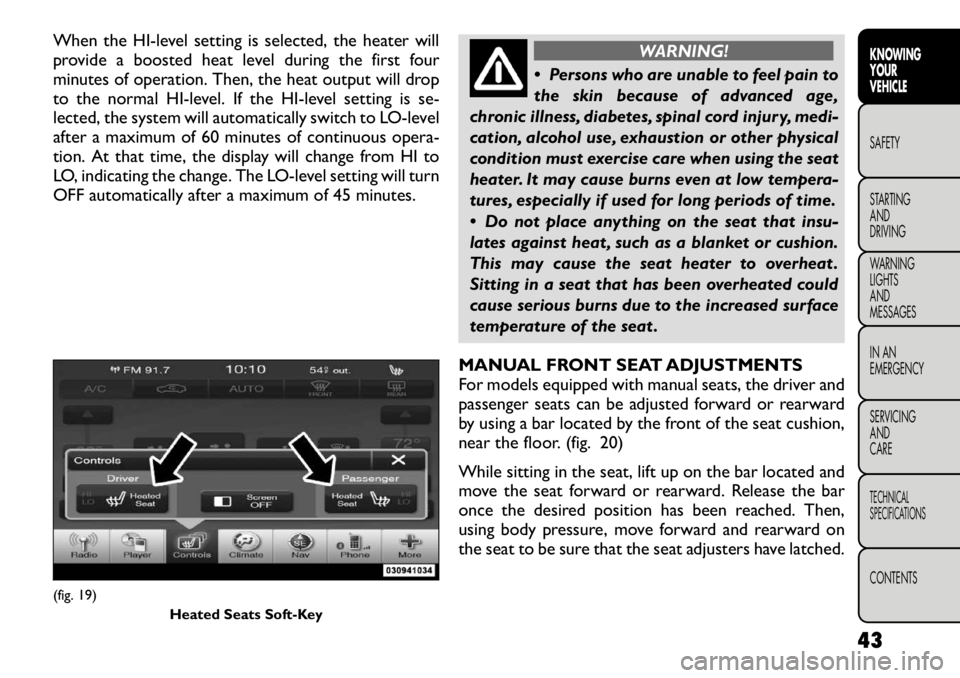
(fig. 19) Heated Seats Soft-Key
43
KNOWING
YOURVEHICLESAFETY
STARTING ANDDRIVING
WARNING LIGHTSAND
MESSAGES
IN AN
EMERGENCY
SERVICING AND
CARETECHNICAL
SPECIFICATIONSCONTENTS
Page 63 of 332

AUTOMATIC DIMMING MIRROR (for
versions/markets, where provided)
This mirror automatically adjusts for headlight glare
from vehicles behind you. This feature will be defaulted
on, and only be disabled when the vehicle is moving in
reverse. (fig. 38)
To avoid damage to the mirror during
cleaning, never spray any cleaning solu-
tion directly onto the mirror. Apply the
solution onto a clean cloth and wipe the mirrorclean. OUTSIDE MIRRORS
To receive maximum benefit, adjust the outside mir-
ror(s) to center on the adjacent lane of traffic and a
slight overlap of the view obtained from the inside
mirror.
NOTE:
The passenger side convex outside mirror
will give a much wider view to the rear, and especially of
the lane next to your vehicle.
WARNING!
Vehicles and other objects seen in the
passenger side convex mirror will look
smaller and farther away than they really are.
Relying too much on your passenger side convex
mirror could cause you to collide with another
vehicle or other object . Use your inside mirror
when judging the size or distance of a vehicle
seen in the passenger side convex mirror. Failure
to follow this warning may result in serious injury
or death.
POWER MIRRORS
The power mirror switch is located on the driver's
door trim panel. (fig. 39)
Models Without Express Window Feature
Press the mirror select button marked L (left) or R
(right) and then press one of the four arrow buttons to
move the mirror in the direction the arrow is pointing.
(fig. 38) Automatic Dimming Mirror
57
KNOWING
YOURVEHICLESAFETY
STARTING ANDDRIVING
WARNING LIGHTSAND
MESSAGES
IN AN
EMERGENCY
SERVICING AND
CARETECHNICAL
SPECIFICATIONSCONTENTS
Page 80 of 332
DIMMER CONTROLS
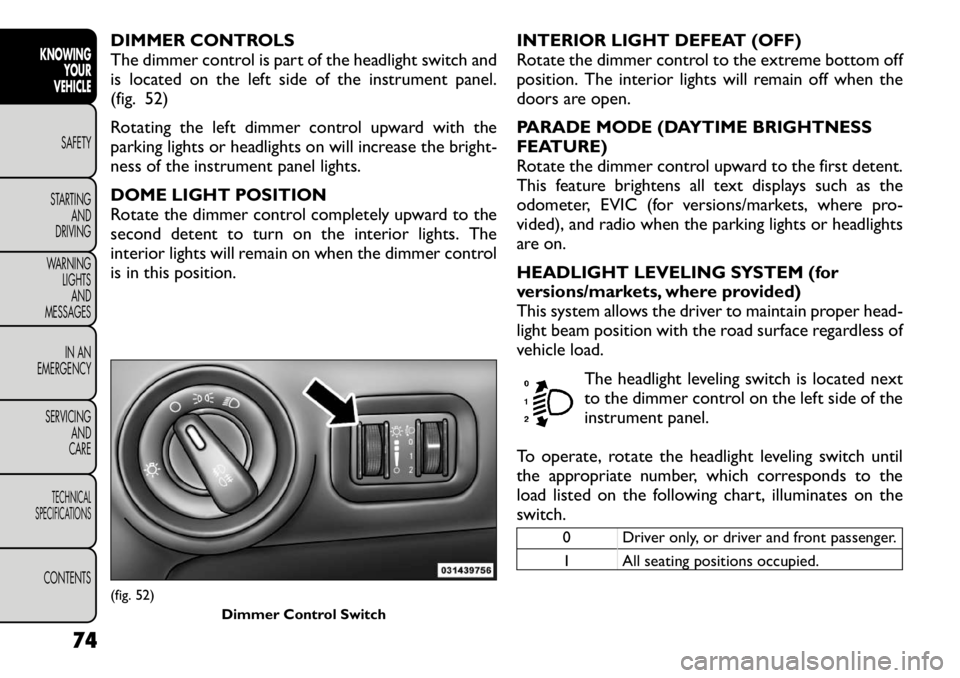
The dimmer control is part of the headlight switch and
is located on the left side of the instrument panel.
(fig. 52)
Rotating the left dimmer control upward with the
parking lights or headlights on will increase the bright-
ness of the instrument panel lights.
DOME LIGHT POSITION
Rotate the dimmer control completely upward to the
second detent to turn on the interior lights. The
interior lights will remain on when the dimmer control
is in this position.INTERIOR LIGHT DEFEAT (OFF)
Rotate the dimmer control to the extreme bottom off
position. The interior lights will remain off when the
doors are open.
PARADE MODE (DAYTIME BRIGHTNESS
FEATURE)
Rotate the dimmer control upward to the first detent.
This feature brightens all text displays such as the
odometer, EVIC (for versions/markets, where pro-
vided), and radio when the parking lights or headlights
are on.
HEADLIGHT LEVELING SYSTEM (for
versions/markets, where provided)
This system allows the driver to maintain proper head-
light beam position with the road surface regardless of
vehicle load.
The headlight leveling switch is located next
to the dimmer control on the left side of the
instrument panel.
To operate, rotate the headlight leveling switch until
the appropriate number, which corresponds to the
load listed on the following chart, illuminates on the
switch.
0 Driver only, or driver and front passenger.
1 All seating positions occupied.
(fig. 52) Dimmer Control Switch
74
KNOWINGYOUR
VEHICLE
SAFETY
STARTING AND
DRIVING
WARNING LIGHTSAND
MESSAGES
IN AN
EMERGENCY
SERVICING AND
CARETECHNICAL
SPECIFICATIONSCONTENTS
Page 118 of 332
ROOF LUGGAGE RACK (for
versions/markets, where
provided)
The roof rack side rails on your vehicle are NOT
designed to carry a load without the addition of cross-
bars. Metal Crossbars can be purchased from your
FIAT dealer to provide a functional roof rack system.
External racks do not increase the total load carrying
capacity of the vehicle. Be sure that the total occupant
and luggage load inside the vehicle plus the load on the
luggage rack do not exceed the maximum vehicle load
capacity.
The roof rack cross rails and side rails together are
designed to carry cargo weight. The load must not
exceed 68 kg, and it should be distributed uniformly
over the cross rails.
To avoid damage to the roof rack and
vehicle, do not exceed the maximum roof
rack load capacity of 68 kg. Always dis-
tribute loads as evenly as possible and secure the
load appropriately.
Long loads, which extend over the windshield,
such as wood panels or surfboards, or loads with
large frontal area should be secured to both the
front and rear of the vehicle.
Place a blanket or other protection between
the surface of the roof and the load.
Travel at reduced speeds and turn corners care-
fully when carrying large or heavy loads on the
roof rack. Wind forces, due to natural causes or
nearby truck traffic , can add sudden upward lift
to loads.This is especially true on large flat loads
and may result in damage to the cargo or your
vehicle.
WARNING!
Cargo must be securely tied before driv-
ing your vehicle. Improperly secured
loads can fly off the vehicle, particularly at high
speeds, resulting in personal injury or property
damage. Follow the Roof Rack Cautions when
carrying cargo on your roof rack.
112
KNOWING YOUR
VEHICLE
SAFETY
STARTING AND
DRIVING
WARNING LIGHTSAND
MESSAGES
IN AN
EMERGENCY
SERVICING AND
CARETECHNICAL
SPECIFICATIONSCONTENTS
Page 123 of 332
ELECTRONIC ROLL MITIGATION (ERM)
This system anticipates the potential for wheel lift by
monitoring the driver’s steering wheel input and the
speed of the vehicle. When ERM determines that the
rate of change of the steering wheel angle and vehicle's
speed are sufficient to potentially cause wheel lift, it
then applies the appropriate brake and may also reduce
engine power to lessen the chance that wheel lift will
occur. ERM will only intervene during very severe or
evasive driving maneuvers. ERM can only reduce the
chance of wheel lift occurring during severe or evasive
driving maneuvers. It cannot prevent wheel lift due to
other factors, such as road conditions, leaving the
roadway, or striking objects or other vehicles.
WARNING!
Many factors, such as vehicle loading,
road conditions, and driving conditions,
influence the chance that wheel lift or rollover
may occur. ERM cannot prevent all wheel lift or
rollovers, especially those that involve leaving the
roadway or striking objects or other vehicles.The
capabilities of an ERM-equipped vehicle must
never be exploited in a reckless or dangerous
manner, which could jeopardize the user's safety
or the safety of others. ELECTRONIC STABILITY CONTROL (ESC)
This system enhances directional control and stability
of the vehicle under various driving conditions. ESC
corrects for over-steering and under-steering the ve-
hicle by applying the brake of the appropriate wheel.
Engine power may also be reduced to help the vehicle
maintain the desired path.
The ESC uses sensors in the vehicle to determine the
path that the driver intends to steer the vehicle and
compares it to the actual path of the vehicle. When the
actual path does not match the intended path, the ESC
applies the brake of the appropriate wheel to assist in
counteracting the condition of over-steer or under-
steer.
• Over-steer - when the vehicle is turning more than
appropriate for the steering wheel position.
• Under-steer - when the vehicle is turning less than appropriate for the steering wheel position.
WARNING!
Electronic Stability Control (ESC)
cannot prevent the natural laws of phys-
ics from acting on the vehicle, nor can it increase
the traction afforded by prevailing road condi-
tions.
(Continued)
117
KNOWING
YOURVEHICLESAFETY
STARTING ANDDRIVING
WARNING LIGHTSAND
MESSAGES
IN AN
EMERGENCY
SERVICING AND
CARETECHNICAL
SPECIFICATIONSCONTENTS