oil FIAT FREEMONT 2012 Owner handbook (in English)
[x] Cancel search | Manufacturer: FIAT, Model Year: 2012, Model line: FREEMONT, Model: FIAT FREEMONT 2012Pages: 332, PDF Size: 5.61 MB
Page 20 of 332
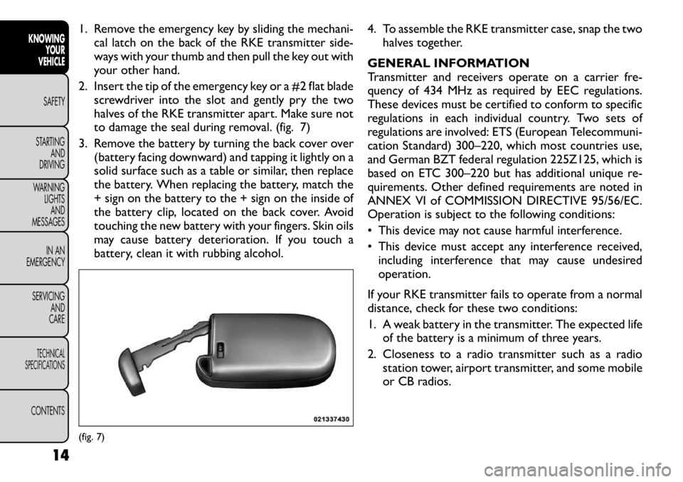
1. Remove the emergency key by sliding the mechani-cal latch on the back of the RKE transmitter side-
ways with your thumb and then pull the key out with
your other hand.
2. Insert the tip of the emergency key or a #2 flat blade screwdriver into the slot and gently pry the two
halves of the RKE transmitter apart. Make sure not
to damage the seal during removal. (fig. 7)
3. Remove the battery by turning the back cover over (battery facing downward) and tapping it lightly on a
solid surface such as a table or similar, then replace
the battery. When replacing the battery, match the
+ sign on the battery to the + sign on the inside of
the battery clip, located on the back cover. Avoid
touching the new battery with your fingers. Skin oils
may cause battery deterioration. If you touch a
battery, clean it with rubbing alcohol. 4. To assemble the RKE transmitter case, snap the two
halves together.
GENERAL INFORMATION
Transmitter and receivers operate on a carrier fre-
quency of 434 MHz as required by EEC regulations.
These devices must be certified to conform to specific
regulations in each individual country. Two sets of
regulations are involved: ETS (European Telecommuni-
cation Standard) 300–220, which most countries use,
and German BZT federal regulation 225Z125, which is
based on ETC 300–220 but has additional unique re-
quirements. Other defined requirements are noted in
ANNEX VI of COMMISSION DIRECTIVE 95/56/EC.
Operation is subject to the following conditions:
• This device may not cause harmful interference.
• This device must accept any interference received, including interference that may cause undesired operation.
If your RKE transmitter fails to operate from a normal
distance, check for these two conditions:
1. A weak battery in the transmitter. The expected life of the battery is a minimum of three years.
2. Closeness to a radio transmitter such as a radio station tower, airport transmitter, and some mobile
or CB radios.(fig. 7)
14
KNOWING YOUR
VEHICLE
SAFETY
STARTING AND
DRIVING
WARNING LIGHTSAND
MESSAGES
IN AN
EMERGENCY
SERVICING AND
CARETECHNICAL
SPECIFICATIONSCONTENTS
Page 26 of 332
DOWN ButtonPress and release the DOWN button to
scroll downward through the main menus
and sub-menus.
SELECT Button Press and release the SELECT button for
access to main menus or sub-menus. Press
and hold the SELECT button for two seconds
to reset features.
BACK Button Press the BACK button to scroll back to a
previous menu or sub-menu.
ELECTRONIC VEHICLE INFORMATION
CENTER (EVIC) DISPLAYS
When the appropriate conditions exist, the EVIC dis-
plays the following messages:
• Turn Signal On (with a continuous warning chime if the vehicle is driven more than 1.6 km with either
turn signal on)
• Left Front Turn Signal Light Out (with a single chime)
• Left Rear Turn Signal Light Out (with a single chime)
• Right Front Turn Signal Light Out (with a single chime)
• Right Rear Turn Signal Light Out (with a single chime)
• RKE Battery Low (with a single chime) • Personal Settings Not Available – Vehicle Not in
PARK (for versions/markets, where provided)
• Left/Right Front Door Ajar (one or more doors open, with a single chime if speed is above 1.6 km/h)
• Left/Right Rear Door Ajar (one or more doors open, with a single chime if speed is above 1.6 km/h)
• Door(s) Ajar (with a single chime if vehicle is in motion)
• Liftgate Ajar (with a single chime)
• Low Washer Fluid (with a single chime)
• Ignition or Accessory On
• Vehicle Not in Park
• Key Left Vehicle
• Key Not Detected
• Low Tire Pressure (with a single chime). Refer to information on “Tire Pressure” and “Tire Pressure
Monitor” in “Starting And Operating”.
• Service TPM System (with a single chime). Refer to information on “Tire Pressure Monitor” in “Starting
And Operating”.
• Check Gascap (refer to “Adding Fuel” in “Technical Specifications”)
• Oil Change Required (with a single chime)
• Check Gascap (refer to “Adding Fuel” in “Starting And Operating”)
• Oil Change Due (with a single chime)
20
KNOWING YOUR
VEHICLE
SAFETY
STARTING AND
DRIVING
WARNING LIGHTSAND
MESSAGES
IN AN
EMERGENCY
SERVICING AND
CARETECHNICAL
SPECIFICATIONSCONTENTS
Page 28 of 332
Windshield Washer Fluid Low IndicatorThis light will turn on to indicate the wind-
shield washer fluid is low.
EVIC RED TELLTALE LIGHTS
This area will show reconfigurable red telltales. These
telltales include:
Door Ajar This light will turn on to indicate that one or
more doors may be ajar.
Oil Pressure Warning Light This light indicates low engine oil pressure. If the
light turns on while driving, stop the vehicle and
shut off the engine as soon as possible. A chime will
sound for four minutes when this light turns on.
Do not operate the vehicle until the cause is corrected.
This light does not show how much oil is in the engine.
The engine oil level must be checked under the hood.
Charging System Light
This light shows the status of the electrical
charging system. The light should come on when
the ignition is first cycled ON and remain on briefly as
a bulb check. If the light stays on or comes on while
driving, turn off some of the vehicle's non-essential
electrical devices or increase engine speed (if at idle). If
the charging system light remains on, it means that the vehicle is experiencing a problem with the charging
system. Obtain SERVICE IMMEDIATELY. See an autho-
rized dealer.
If jump starting is required, refer to “Jump Starting
Procedures” in “In An Emergency”.
Electronic Throttle Control (ETC) Light
This light informs you of a problem with the
Electronic Throttle Control (ETC) system.
The light will come on when the ignition is
first turned ON and remain on briefly as a
bulb check. If the light does not come on during
starting, have the system checked by an authorized
dealer.
If a problem is detected, the light will come on while
the engine is running. Cycle the ignition key when the
vehicle has completely stopped and the shift lever is
placed in the PARK position. The light should turn off.
If the light remains lit with the engine running, your
vehicle will usually be drivable. However, see an autho-
rized dealer for service as soon as possible. If the light
is flashing when the engine is running, immediate ser-
vice is required. You may experience reduced perfor-
mance, an elevated/rough idle or engine stall and your
vehicle may require towing.
Engine Temperature Warning Light
This light warns of an overheated engine condi-
tion. As temperatures rise and the gauge ap-
proaches H,this indicator will illuminate and a
single chime will sound after reaching a set threshold.
22
KNOWING YOUR
VEHICLE
SAFETY
STARTING AND
DRIVING
WARNING LIGHTSAND
MESSAGES
IN AN
EMERGENCY
SERVICING AND
CARETECHNICAL
SPECIFICATIONSCONTENTS
Page 29 of 332
Further overheating will cause the temperature gauge
to passH,the indicator will continuously flash and a
continuous chime will occur until the engine is allowed
to cool.
If the light turns on while driving, safely pull over and
stop the vehicle. If the A/C system is on, turn it off.
Also, shift the transmission into NEUTRAL and idle the
vehicle. If the temperature reading does not return to
normal, turn the engine off immediately and call for
service.
Transmission Temperature Warning Light This light indicates that the transmission fluid
temperature is running hot. This may occur
with severe usage, such as trailer towing. If
this light turns on, safely pull over and stop
the vehicle. Then, shift the transmission into NEU-
TRAL and run the engine at idle or faster until the light
turns off.
Continuous driving with the Transmission
Temperature Warning Light illuminated
will eventually cause severe transmission
damage or transmission failure.
WARNING!
If the Transmission Temperature Warning
Light is illuminated and you continue
operating the vehicle, in some circumstances you
could cause the fluid to boil over, come in contact
with hot engine or exhaust components and
cause a fire.
OIL CHANGE DUE
Your vehicle is equipped with an engine oil change
indicator system. The “Oil Change Due” message will
flash in the EVIC display for approximately 10 seconds
after a single chime has sounded to indicate the next
scheduled oil change interval. The engine oil change
indicator system is duty cycle based, which means the
engine oil change interval may fluctuate dependent
upon your personal driving style.
Unless reset, this message will continue to display each
time you cycle the ignition to the ON/RUN position.
To turn off the message temporarily, press and release
the BACK button. To reset the oil change indicator
system please refer to a Fiat Dealership.
FUEL ECONOMY
Press and release the UP or DOWN button until “Fuel
Economy” displays highlighted in the EVIC and press
the SELECT button. The following Fuel Economy func-
tions will display in the EVIC:
23KNOWING
YOURVEHICLESAFETY
STARTING ANDDRIVING
WARNING LIGHTSAND
MESSAGES
IN AN
EMERGENCY
SERVICING AND
CARETECHNICAL
SPECIFICATIONSCONTENTS
Page 31 of 332

TRIP INFO
Press and release the UP or DOWN button until “Trip
Info” displays highlighted in the EVIC and press the
SELECT button. Pressing the SELECT button with
"Trip Info" highlighted will cause the EVIC display to
show Trip A, Trip B, and Elapsed Time all in one display.
If you want to reset one of the three functions you use
the UP or DOWN buttons to highlight (select) the
feature that you want to reset. Pressing the SELECT
button will cause the selected feature to reset individu-
ally. The three features can only be reset individually.
The following Trip functions display in the EVIC:
• Trip A
• Trip B
• Elapsed Time
The Trip Functions mode displays the following infor- mation:
Trip A
Shows the total distance traveled for Trip A since the
last reset.
Trip B
Shows the total distance traveled for Trip B since the
last reset.
Elapsed Time
Shows the total elapsed time of travel since the last
reset. Elapsed time will increment when the ignition is
in the ON/RUN position.To Reset The Display
Reset will only occur while a resettable function is
being displayed. Press and release the SELECT button
once to clear the resettable function.
TIRE BAR
Press and release the UP or DOWN button until “Tire
BAR” displays highlighted in the EVIC. Press the SE-
LECT button to view a graphic of the vehicle with a tire
pressure value at each corner of the graphic.
VEHICLE INFO (CUSTOMER
INFORMATION FEATURES) (for
versions/markets, where provided)
Press and release the UP or DOWN button until
“Vehicle Info” displays in the EVIC and press the SE-
LECT button. Press the UP and DOWN button to
scroll through the available information displays that
may be equipped.
Coolant Temp
Displays the actual coolant temperature.
Oil Temperature
Displays the actual oil temperature.
Oil Pressure
Displays the actual oil pressure.
Trans Temperature
Displays the actual transmission temperature.
Engine Hours
Displays the number of hours of engine operation.
25
KNOWING
YOURVEHICLESAFETY
STARTING ANDDRIVING
WARNING LIGHTSAND
MESSAGES
IN AN
EMERGENCY
SERVICING AND
CARETECHNICAL
SPECIFICATIONSCONTENTS
Page 166 of 332
(Continued)
Two people should never be belted into a single
seat belt . People belted together can crash into
one another in an accident , hurting one another
badly. Never use a lap/shoulder belt or a lap belt
for more than one person, no matter what their
size.
Belts should not be worn with straps twisted.
Care should be taken to avoid contamination
of the webbing with polishes, oils and chemicals,
and particularly battery acid. Cleaning may be
safely carried out using mild soap and water.The
belt should be replaced if webbing becomes
frayed, contaminated, or damaged.
Lap/Shoulder Belt Operating Instructions
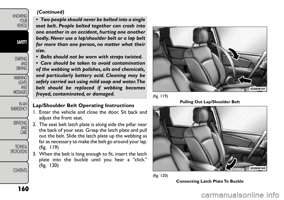
1. Enter the vehicle and close the door. Sit back and adjust the front seat.
2. The seat belt latch plate is along side the pillar near the back of your seat. Grasp the latch plate and pull
out the belt. Slide the latch plate up the webbing as
far as necessary to make the belt go around your lap.
(fig. 119)
3. When the belt is long enough to fit, insert the latch plate into the buckle until you hear a “click.”
(fig. 120)
(fig. 119) Pulling Out Lap/Shoulder Belt(fig. 120)
Connecting Latch Plate To Buckle
160
KNOWING YOUR
VEHICLESAFETYSTARTING AND
DRIVING
WARNING LIGHTSAND
MESSAGES
IN AN
EMERGENCY
SERVICING AND
CARETECHNICAL
SPECIFICATIONSCONTENTS
Page 199 of 332
The best protection against carbon monoxide entry
into the vehicle body is a properly maintained engine
exhaust system.
Whenever a change is noticed in the sound of the
exhaust system, when exhaust fumes can be detected
inside the vehicle, or when the underside or rear of the
vehicle is damaged, have a competent mechanic inspect
the complete exhaust system and adjacent body areas
for broken, damaged, deteriorated, or mispositioned
parts. Open seams or loose connections could permit
exhaust fumes to seep into the passenger compart-
ment. In addition, inspect the exhaust system each time
the vehicle is raised for lubrication or oil change.
Replace as required.
SAFETY CHECKS YOU SHOULD MAKE
INSIDE THE VEHICLE
Seat Belts
Inspect the seat belt system periodically, checking for
cuts, frays, and loose parts. Damaged parts must be
replaced immediately. Do not disassemble or modify
the system.
Front seat belt assemblies must be replaced after a
collision. Rear seat belt assemblies must be replaced
after a collision if they have been damaged (i.e., bent
retractor, torn webbing, etc.). If there is any question
regarding belt or retractor condition, replace the seatbelt.Air Bag Warning Light
The light should turn on and remain on for four to six
seconds as a bulb check when the ignition switch is first
turned ON. If the light is not lit during starting, or if the
light stays on, flickers, or turns on while driving, have
the system checked by an authorized dealer.
Defroster
Check operation by selecting the defrost mode and
place the blower control on high speed. You should be
able to feel the air directed against the windshield. See
your authorized dealer for service if your defroster is
inoperable.
Floor Mat Safety Information
Always use floor mats designed to fit the footwell of
your vehicle. Use only floor mats that leave the pedal
area unobstructed and that are firmly secured so that
they cannot slip out of position and interfere with the
pedals or impair safe operation of your vehicle in other
ways.
WARNING!
Pedals that cannot move freely can
cause loss of vehicle control and increase
the risk of serious personal injury.
Always make sure that floor mats are properly
attached to the floor mat fasteners.
(Continued)
193
KNOWING
YOURVEHICLESAFETYSTARTING ANDDRIVING
WARNING LIGHTSAND
MESSAGES
IN AN
EMERGENCY
SERVICING AND
CARETECHNICAL
SPECIFICATIONSCONTENTS
Page 200 of 332
(Continued)
Never place or install floor mats or other floor
coverings in the vehicle that cannot be properly
secured to prevent them from moving and inter-
fering with the pedals or the ability to control the
vehicle.
Never put floor mats or other floor coverings
on top of already installed floor mats. Additional
floor mats and other coverings will reduce the
size of the pedal area and interfere with the
pedals.
Check mounting of mats on a regular basis.
Always properly reinstall and secure floor mats
that have been removed for cleaning.
Always make sure that objects cannot fall into
the driver footwell while the vehicle is moving.
Objects can become trapped under the brake
pedal and accelerator pedal causing a loss of
vehicle control.
If required, mounting posts must be properly
installed, if not equipped from the factory.
Failure to properly follow floor mat installation
or mounting can cause interference with the
brake pedal and accelerator pedal operation
causing loss of control of the vehicle. PERIODIC SAFETY CHECKS YOU SHOULD
MAKE OUTSIDE THE VEHICLE
Tires
Examine tires for excessive tread wear and uneven
wear patterns. Check for stones, nails, glass, or other
objects lodged in the tread or sidewall. Inspect the
tread for cuts and cracks. Inspect sidewalls for cuts,
cracks and bulges. Check the wheel nuts for tightness.
Check the tires (including spare) for proper cold infla-
tion pressure.
Lights
Have someone observe the operation of exterior lights
while you work the controls. Check Turn Signal and
High Beam Indicator Lights on the instrument panel.
Door Latches
Check for positive closing, latching, and locking.
Fluid Leaks
Check area under vehicle after overnight parking for
fuel, engine coolant, oil, or other fluid leaks. Also, if
gasoline fumes are detected or if fuel, power steering
fluid, or brake fluid leaks are suspected, the cause
should be located and corrected immediately.
194
KNOWING YOUR
VEHICLESAFETYSTARTING AND
DRIVING
WARNING LIGHTSAND
MESSAGES
IN AN
EMERGENCY
SERVICING AND
CARETECHNICAL
SPECIFICATIONSCONTENTS
Page 201 of 332
STARTING AND DRIVING
ENGINE BREAK-IN
RECOMMENDATIONS
A long break-in period is not required for the engine
and drivetrain (transmission and axle) in your vehicle.
Drive moderately during the first 500 km. After the
initial 100 km, speeds up to 80 or 90 km/h are desirable.
While cruising, brief full-throttle acceleration, within
the limits of local traffic laws contributes to a good
break-in. Wide-open throttle acceleration in low gear
can be detrimental and should be avoided.
The engine oil installed in the engine at the factory is a
high-quality energy-conserving type lubricant. Oil
changes should be consistent with anticipated climate
conditions under which vehicle operations will occur.
For the recommended viscosity and quality grades,
refer to “Maintenance Procedures” in “Maintaining
Your Vehicle”. NON-DETERGENT OR STRAIGHT
MINERAL OILS MUST NEVER BE USED.
A new engine may consume some oil during its first few
thousand kilometers of operation. This should be con-
sidered a normal part of the break-in and not inter-
preted as an indication of difficulty. STARTING PROCEDURES
Before starting your vehicle, adjust your seat, adjust the
inside and outside mirrors, fasten your seat belt, and if
present, instruct all other occupants to buckle their
seat belts.
WARNING!
Before exiting a vehicle, always apply
the parking brake, shift the transmission
into PARK, and remove the key fob from the
ignition. When leaving the vehicle, always lock
your vehicle.
Never leave children alone in a vehicle, or with
access to an unlocked vehicle.
Allowing children to be in a vehicle unattended
is dangerous for a number of reasons. A child or
others could be seriously or fatally injured. Chil-
dren should be warned not to touch the parking
brake, brake pedal or the shift lever.
Do not leave the key fob in or near the vehicle,
and do not leave Keyless Enter-N-Go in the ACC
or ON/RUN mode. A child could operate power
windows, other controls, or move the vehicle.
(Continued)
195
KNOWING
YOURVEHICLE SAFETYSTARTING ANDDRIVINGWARNING LIGHTSAND
MESSAGES
IN AN
EMERGENCY
SERVICING AND
CARETECHNICAL
SPECIFICATIONSCONTENTS
Page 204 of 332

motor will engage automatically, run for 10 seconds,
and then disengage. Once this occurs, release the
accelerator pedal and the brake pedal, wait 10 to
15 seconds, then repeat the “Normal Starting”
procedure.
AFTER STARTING
The idle speed is controlled automatically and it will
decrease as the engine warms up.
NORMAL STARTING – DIESEL ENGINE
Using The ENGINE START/STOP Button
1. Turn the ignition switch to the ON position bypressing the ENGINE START/STOP button twice.
2. Watch the “Wait To Start Indicator Light” in the instrument cluster. Refer to “Instrument Cluster” in
“Warning Lights And Messages” for further infor-
mation. It will illuminate for two to ten seconds or
more, depending on engine temperature. When the
“Wait To Start Indicator Light” goes out, the engine
is ready to start.
3. DO NOT press the accelerator. To start the engine, the transmission must be in PARK or NEUTRAL.
Press the brake pedal (automatic transmission only)
or press and hold the clutch pedal (manual transmis-
sion only) while pressing and holding the ENGINE
START/STOP button. Release the button when the
engine starts. NOTE:
The starter motor may need to remain en-
gaged for up to 30 seconds in very cold conditions until
the engine is started. If the vehicle does not start,
release the button. Wait for 25-30 seconds and then
try to start again.
4. After the engine starts, allow it to idle for approxi- mately 30 seconds before driving. This allows oil to
circulate and lubricate the turbocharger.
To Turn Off The Engine Using ENGINE
START/STOP Button
1. With the vehicle stopped, place the shift lever in NEUTRAL, then press and release the ENGINE
START/STOP button.
2. The ignition switch will return to the OFF position.
3. Place the shift lever in first gear or Reverse and then apply the parking brake.
NOTE:
• If the ignition switch is left in the ACC position, the
system will automatically time out after 30 minutes of
inactivity and the ignition will switch to the OFF posi-tion.
• If the ignition switch is left in the RUN position, the
system will automatically time out after 30 minutes of
inactivity if the vehicle speed is 0 km/h and the engine is
not running.
• If the vehicle speed is above 8 km/h, the ENGINE
START/STOP button must be held for two seconds
198
KNOWING YOUR
VEHICLE
SAFETYSTARTING AND
DRIVINGWARNING LIGHTSAND
MESSAGES
IN AN
EMERGENCY
SERVICING AND
CARETECHNICAL
SPECIFICATIONSCONTENTS