ECO mode FIAT FREEMONT 2013 Owner handbook (in English)
[x] Cancel search | Manufacturer: FIAT, Model Year: 2013, Model line: FREEMONT, Model: FIAT FREEMONT 2013Pages: 352, PDF Size: 5.22 MB
Page 77 of 352
Rear Lock
Pressing the Rear Temperature Lock soft-key on the
Uconnect Touch™ screen, illuminates a lock symbol in
the rear display. The rear temperature and air source
are controlled from the front Uconnect Touch™ sys-
tem.
Rear second row occupants can only adjust the rear
ATC control when the Rear Temperature Lock button
is turned off.
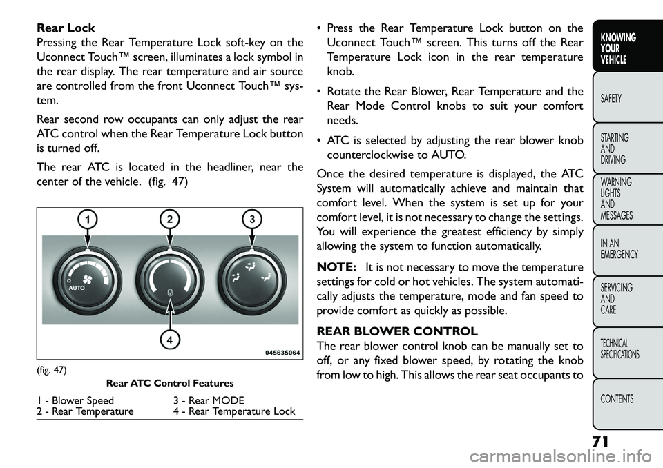
The rear ATC is located in the headliner, near the
center of the vehicle. (fig. 47) Press the Rear Temperature Lock button on the
Uconnect Touch™ screen. This turns off the Rear
Temperature Lock icon in the rear temperature
knob.
Rotate the Rear Blower, Rear Temperature and the Rear Mode Control knobs to suit your comfort
needs.
ATC is selected by adjusting the rear blower knob counterclockwise to AUTO.
Once the desired temperature is displayed, the ATC
System will automatically achieve and maintain that
comfort level. When the system is set up for your
comfort level, it is not necessary to change the settings.
You will experience the greatest efficiency by simply
allowing the system to function automatically.
NOTE: It is not necessary to move the temperature
settings for cold or hot vehicles. The system automati-
cally adjusts the temperature, mode and fan speed to
provide comfort as quickly as possible.
REAR BLOWER CONTROL
The rear blower control knob can be manually set to
off, or any fixed blower speed, by rotating the knob
from low to high. This allows the rear seat occupants to(fig. 47) Rear ATC Control Features1 - Blower Speed 3 - Rear MODE
2 - Rear Temperature 4 - Rear Temperature Lock
71
KNOWING
YOUR
VEHICLE
SAFETY
S
TARTING
AND
DRIVING
WARNING
LIGHTS
AND
MESSAGES
IN AN
EMERGENCY
SERVICING
AND
CARETECHNICAL
SPECIFICATIONSCONTENTS
Page 79 of 352
Summer Operation
The engine cooling system in air-conditioned vehicles
must be protected with a high-quality antifreeze cool-
ant to provide proper corrosion protection and to
protect against engine overheating. A solution of 50%
ethylene glycol antifreeze coolant and 50% water is
recommended. Refer to “Maintenance Procedures” in
“Servicing And Care” for proper coolant selection.
Winter Operation
Use of the air Recirculation mode during Winter
months is not recommended because it may cause
window fogging.
Vacation Storage
Any time you store your vehicle or keep it out of
service (i.e., vacation) for two weeks or more, run the
air conditioning system at idle for about five minutes in
the fresh air and high blower setting. This will ensure
adequate system lubrication to minimize the possibility
of compressor damage when the system is started
again.
Window Fogging
Interior fogging on the windshield can be quickly re-
moved by turning the mode selector to Defrost. The
Defrost/Floor mode can be used to maintain a clear
windshield and provide sufficient heating. If side win-
dow fogging becomes a problem, increase the blowerspeed. Vehicle windows tend to fog on the inside in
mild but rainy or humid weather.
NOTE:
Recirculation mode without A/C should not
be used for long periods, as fogging may occur.
Outside Air Intake
Make sure the air intake, located directly in front of the
windshield, is free of obstructions such as leaves.
Leaves collected in the air intake may reduce airflow,
and if they enter the plenum, they could plug the water
drains. In winter months, make sure the air intake is
clear of ice, slush, and snow.
A/C Air Filter
The climate control system filters outside air contain-
ing dust, pollen and some odors. Strong odors cannot
be totally filtered out. Refer to “Maintenance Proce-
dures” in “Servicing And Care” for filter replacement
instructions.
73
KNOWING
YOUR
VEHICLE
SAFETY
STARTING
AND
DRIVING
WARNING
LIGHTS
AND
MESSAGES
IN AN
EMERGENCY
SERVICING
AND
CARETECHNICAL
SPECIFICATIONSCONTENTS
Page 81 of 352
LIGHTS
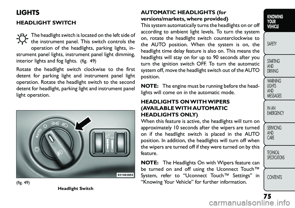
HEADLIGHT SWITCHThe headlight switch is located on the left side of
the instrument panel. This switch controls the
operation of the headlights, parking lights, in-
strument panel lights, instrument panel light dimming,
interior lights and fog lights. (fig. 49)
Rotate the headlight switch clockwise to the first
detent for parking light and instrument panel light
operation. Rotate the headlight switch to the second
detent for headlight, parking light and instrument panel
light operation. AUTOMATIC HEADLIGHTS (for
versions/markets, where provided)
This system automatically turns the headlights on or off
according to ambient light levels. To turn the system
on, rotate the headlight switch counterclockwise to
the AUTO position. When the system is on, the
headlight time delay feature is also on. This means the
headlights will stay on for up to 90 seconds after you
turn the ignition switch OFF. To turn the automatic
system off, move the headlight switch out of the AUTO
position.
NOTE:
The engine must be running before the head-
lights will come on in the automatic mode.
HEADLIGHTS ON WITH WIPERS
(AVAILABLE WITH AUTOMATIC
HEADLIGHTS ONLY)
When this feature is active, the headlights will turn on
approximately 10 seconds after the wipers are turned
on if the headlight switch is placed in the AUTO
position. In addition, the headlights will turn off when
the wipers are turned off if they were turned on by this
feature.
NOTE: The Headlights On with Wipers feature can
be turned on and off using the Uconnect Touch™
System, refer to “Uconnect Touch™ Settings” in
“Knowing Your Vehicle” for further information.(fig. 49) Headlight Switch
75
KNOWING
YOUR
VEHICLE
SAFETY
S
TARTING
AND
DRIVING
WARNING
LIGHTS
AND
MESSAGES
IN AN
EMERGENCY
SERVICING
AND
CARETECHNICAL
SPECIFICATIONSCONTENTS
Page 84 of 352
INTERIOR LIGHTS
The interior lights come on when a door is opened.
To protect the battery, the interior lights will turn off
automatically 10 minutes after the ignition switch is
moved to the LOCK position. This will occur if the
interior lights were switched on manually or are on
because a door is open. This includes the glove box
light, but not the trunk light. To restore interior light
operation, either turn the ignition switch ON or cycle
the light switch.
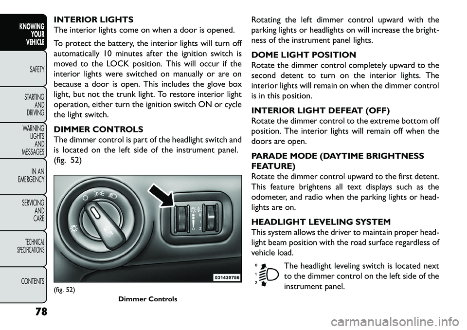
DIMMER CONTROLS
The dimmer control is part of the headlight switch and
is located on the left side of the instrument panel.
(fig. 52)Rotating the left dimmer control upward with the
parking lights or headlights on will increase the bright-
ness of the instrument panel lights.
DOME LIGHT POSITION
Rotate the dimmer control completely upward to the
second detent to turn on the interior lights. The
interior lights will remain on when the dimmer control
is in this position.
INTERIOR LIGHT DEFEAT (OFF)
Rotate the dimmer control to the extreme bottom off
position. The interior lights will remain off when the
doors are open.
PARADE MODE (DAYTIME BRIGHTNESS
FEATURE)
Rotate the dimmer control upward to the first detent.
This feature brightens all text displays such as the
odometer, and radio when the parking lights or head-
lights are on.
HEADLIGHT LEVELING SYSTEM
This system allows the driver to maintain proper head-
light beam position with the road surface regardless of
vehicle load.
The headlight leveling switch is located next
to the dimmer control on the left side of the
instrument panel.(fig. 52) Dimmer Controls
78
KNOWINGYOUR
VEHICLE
SAFETY
S
TARTING AND
DRIVING
WARNING LIGHTSAND
MESSAGES
IN AN
EMERGENCY
SERVICING AND
CARETECHNICAL
SPECIFICATIONSCONTENTS
Page 105 of 352
WARNING!
N
ever leave children in a vehicle with
the key in the ignition switch (or with
the ignition in the Accessory or Run position, for
vehicles equipped with Keyless Enter-N-Go™).
Occupants, particularly unattended children, can
become entrapped by the power sunroof while
operating the power sunroof switch. Such entrap-
ment may result in serious injury or death.
In a collision, there is a greater risk of being
thrown from a vehicle with an open sunroof.You
could also be seriously injured or killed. Always
fasten your seat belt properly and make sure all
passengers are also properly secured.
Do not allow small children to operate the
sunroof. Never allow your fingers, other body
parts, or any object , to project through the sun-
roof opening. Injury may result .
OPENING SUNROOF — EXPRESS
Press the switch rearward and release it within one-half
second and the sunroof will open automatically from
any position. The sunroof will open fully and stop
automatically. This is called “Express Open”. During
Express Open operation, any movement of the sunroof
switch will stop the sunroof. OPENING SUNROOF — MANUAL MODE
To open the sunroof, press and hold the switch rear-
ward to full open. Any release of the switch will stop
the movement and the sunroof will remain in a partially
opened condition until the switch is pushed and held
rearward again.
CLOSING SUNROOF — EXPRESS
Press the switch forward and release it within one-half
second and the sunroof will close automatically from
any position. The sunroof will close fully and stop
automatically. This is called “Express Close”. During
Express Close operation, any movement of the switch
will stop the sunroof.
CLOSING SUNROOF — MANUAL MODE
To close the sunroof, press and hold the switch in the
forward position. Any release of the switch will stop
the movement and the sunroof will remain in a partially
closed condition until the switch is pushed and held
forward again.
PINCH PROTECT FEATURE
This feature will detect an obstruction in the opening
of the sunroof during Express Close operation. If an
obstruction in the path of the sunroof is detected, the
sunroof will automatically retract. Remove the ob-
struction if this occurs. Next, press the switch forward
and release to Express Close.
99
KNOWING
YOUR
VEHICLE
SAFETY
S
TARTING
AND
DRIVING
WARNING
LIGHTS
AND
MESSAGES
IN AN
EMERGENCY
SERVICING
AND
CARETECHNICAL
SPECIFICATIONSCONTENTS
Page 109 of 352
Automatic Unlock Doors On Exit
Programming
The Automatic Unlock Doors On Exit feature can be
enabled or disabled as follows:
For vehicles equipped with the Uconnect Touch™,refer to “Uconnect Touch™ Settings” in “Knowing
Your Vehicle” for further information.
For vehicles not equipped with the Uconnect Touch™, perform the following steps:
1. Enter the vehicle and close all doors.
2. Place the Key Fob in the ignition switch.
3. Within 15 seconds, cycle the ignition switch be- tween LOCK and ON/RUN and then back to LOCK
four times ending up in the LOCK position. How-
ever, do not start the engine.
4. Within 30 seconds, press the power door unlock switch to unlock the doors.
5. A single chime will indicate the completion of the programming. NOTE:
If you do not hear the chime, it means that
the system did not enter the programming mode and
you will need to repeat the procedure.
6. Repeat these steps if you want to return this feature to its previous setting.
NOTE: Use the Automatic Unlock Doors On Exit
feature in accordance with local laws.
103
KNOWING
YOUR
VEHICLE
SAFETY
STARTING
AND
DRIVING
WARNING
LIGHTS
AND
MESSAGES
IN AN
EMERGENCY
SERVICING
AND
CARETECHNICAL
SPECIFICATIONSCONTENTS
Page 115 of 352
NOTE:For vehicles equipped with the Uconnect
Touch™, the power window switches will remain ac-
tive for up to 10 minutes after the ignition is cycled to
the OFF position. Opening either front door will cancel
this feature. The time is programmable. Refer to
“Uconnect Touch™ Settings” in “Knowing Your Ve-
hicle” for further information.
WARNING!
Never leave children in a vehicle with
t
he Key Fob. Occupants, particularly un-
attended children, can become entrapped by the
windows while operating the power window
switches. Such entrapment may result in serious
injury or death.
Auto-Down Feature
The driver's power window switch has an Auto-down
feature. Press the window switch past the first detent,
release, and the window will go down automatically.
To open the window part way, press the window
switch to the first detent and release it when you want
the window to stop.
To stop the window from going all the way down during
the Auto-down operation, pull up on the switch briefly. Auto-Up Feature With Anti-Pinch Protection
(for versions/markets, where provided)
On some models, the driver's and front passenger's
power window switch has an Auto-up feature. Pull the
window switch up to the second detent, release, and
the window will go up automatically.
To stop the window from going all the way up during
the Auto-up operation, push down on the switch
briefly.
To close the window part way, pull the window switch
up to the first detent and release it when you want the
window to stop.
NOTE:
If the window runs into any obstacle during Auto-
closure, it will reverse direction and then go back
down. Remove the obstacle and use the window
switch again to close the window.
Any impact due to rough road conditions may trigger the auto-reverse function unexpectedly during auto-
closure. If this happens, pull the switch lightly to the
first detent and hold to close window manually.
109
KNOWING
YOUR
VEHICLE
SAFETY
STARTING
AND
DRIVING
WARNING
LIGHTS
AND
MESSAGES
IN AN
EMERGENCY
SERVICING
AND
CARETECHNICAL
SPECIFICATIONSCONTENTS
Page 120 of 352
WARNING!
The weight and position of cargo and
pass
engers can change the vehicle cen-
ter of gravity and vehicle handling.To avoid loss of
control resulting in personal injury, follow these
guidelines for loading your vehicle:
Do not carry loads that exceed the load limits de- scribed on the label attached to the left door or left
door center pillar.
Always place cargo evenly on the cargo floor. Put heavier objects as low and as far forward as possible.
Place as much cargo as possible in front of the rear axle. Too much weight or improperly placed weight
over or behind the rear axle can cause the vehicle to
sway.
Do not pile luggage or cargo higher than the top of the seatback. This could impair visibility or become a
dangerous projectile in a sudden stop or collision.
To help protect against personal injury, passengers should not be seated in the rear cargo area. The rear
cargo space is intended for load carrying purposes
only, not for passengers, who should sit in seats and
use seat belts. RETRACTABLE CARGO AREA COVER (for
versions/markets, where provided) — FIVE
PASSENGER MODELS
NOTE:
The purpose of this cover is for privacy, not
to secure loads. It will not prevent cargo from shifting
or protect passengers from loose cargo.
The removable retractable cargo area cover mounts in
the cargo area behind the top of the rear seats.
The cover, when extended, covers the cargo area to
keep items out of sight. Notches in the trim panels near
the liftgate opening secure the extended cover in place.
The cover rolls away neatly inside its housing when not
in use. You can also remove the cover from the vehicle
to make more room in the cargo area.
To install the cover, position it in the vehicle so that the
flat side of the housing faces upward. Then, insert
either the left or the right spring-loaded post (located
on the ends of the cover housing) into the left attach-
ment point or the right attachment point (shown).
(fig. 95)
114
KNOWING YOUR
VEHICLE
SAFETY
S
TARTING AND
DRIVING
WARNING LIGHTSAND
MESSAGES
IN AN
EMERGENCY
SERVICING AND
CARETECHNICAL
SPECIFICATIONSCONTENTS
Page 131 of 352
WARNING!
When in “Partial Off ” mode, the TCS
fun
ctionality of ESC (except for the lim-
ited slip feature described in the TCS section) has
been disabled and the “ESC Off Indicator Light”
will be illuminated. All other stability features of
ESC function normally. When in “Partial Off ”
mode, the engine power reduction of TCS is dis-
abled, and the enhanced vehicle stability offered
by the ECS system is reduced.
ESC ACTIVATION/MALFUNCTION
INDICATOR LIGHT AND ESC OFF
INDICATOR LIGHT
The “ESC Activation/Malfunction Indicator
Light” in the instrument cluster will come on
when the ignition switch is turned to the ON
position. It should go out with the engine
running. If the “ESC Activation/Malfunction Indicator
Light” comes on continuously with the engine running,
a malfunction has been detected in the ESC system. If
this light remains on after several ignition cycles, and
the vehicle has been driven several kilometers at
speeds greater than 48 km/h, see your authorized
dealer as soon as possible to have the problem diag-
nosed and corrected. The “ESC Activation/Malfunction Indicator Light” (lo-
cated in the instrument cluster) starts to flash as soon
as the tires lose traction and the ESC system becomes
active. The “ESC Activation/Malfunction Indicator
Light” also flashes when TCS is active. If the “ESC
Activation/Malfunction Indicator Light” begins to flash
during acceleration, ease up on the accelerator and
apply as little throttle as possible. Be sure to adapt your
speed and driving to the prevailing road conditions.
NOTE:
The “ESC Activation/Malfunction Indicator Light”
and the “ESC OFF Indicator Light” come on momen-
tarily each time the ignition switch is turned ON.
Each time the ignition is turned ON, the ESC system will be ON even if it was turned off previously.
The ESC system will make buzzing or clicking sounds when it is active. This is normal; the sounds will stop
when ESC becomes inactive following the maneuver
that caused the ESC activation.
The “ESC OFF Indicator Light” indicates the
Electronic Stability Control (ESC) is off.
125KNOWING
YOUR
VEHICLE
SAFETY
S
TARTING
AND
DRIVING
WARNING
LIGHTS
AND
MESSAGES
IN AN
EMERGENCY
SERVICING
AND
CARETECHNICAL
SPECIFICATIONSCONTENTS
Page 132 of 352
TRAILER SWAY CONTROL (TSC)
TSC uses sensors in the vehicle to recognize an exces-
sively swaying trailer. TSC activates automatically once
the excessively swaying trailer is recognized. When
TSC is functioning, the “ESC Activation/Malfunction
Indicator Light” will flash, the engine power will be
reduced, and you will feel the brake being applied to
individual wheels in an attempt to stop the trailer from
swaying.
NOTE:The TSC is disabled when the ESC system is
in the “Partial Off ” mode.
WARNING!
TS
C cannot stop all trailers from
swaying. Always use caution when tow-
ing a trailer and follow the tongue weight recom-
mendations. Refer to “Trailer Towing” in “Starting
and Driving” for further information.
If TSC activates while towing a trailer, stop the
vehicle at the nearest safe location and adjust
the trailer load to eliminate the trailer sway.
Failure to follow these warnings can result in
an accident or serious personal injury. ONBOARD DIAGNOSTIC SYSTEM —
OBD II
Your vehicle is equipped with a sophisticated onboard
diagnostic system called OBD II. This system monitors
the performance of the emissions, engine, and auto-
matic transmission control systems. When these sys-
tems are operating properly, your vehicle will provide
excellent performance and fuel economy, as well as
engine emissions well within current government regu-
lations.
If any of these systems require service, the OBD II
system will turn on the “Malfunction Indicator Light”
(MIL). It will also store diagnostic codes and other
information to assist your service technician in making
repairs. Although your vehicle will usually be drivable
and not need towing, see your authorized dealer for
service as soon as possible.
126
KNOWING YOUR
VEHICLE
SAFETY
S
TARTING AND
DRIVING
WARNING LIGHTSAND
MESSAGES
IN AN
EMERGENCY
SERVICING AND
CARETECHNICAL
SPECIFICATIONSCONTENTS