steering FIAT FREEMONT 2013 Owner handbook (in English)
[x] Cancel search | Manufacturer: FIAT, Model Year: 2013, Model line: FREEMONT, Model: FIAT FREEMONT 2013Pages: 352, PDF Size: 5.22 MB
Page 127 of 352
(Continued)
Pumping of the Anti-Lock Brakes will diminish
their effectiveness and may lead to an accident .
Pumping makes the stopping distance longer. Just
press firmly on your brake pedal when you need
to slow down or stop.
The ABS cannot prevent the natural laws of
physics from acting on the vehicle, nor can it
increase braking or steering efficiency beyond
that afforded by the condition of the vehicle
brakes and tires or the traction afforded.
The ABS cannot prevent accidents, including
those resulting from excessive speed in turns,
following another vehicle too closely, or hydro-
planing.
The capabilities of an ABS equipped vehicle
must never be exploited in a reckless or danger-
ous manner, which could jeopardize the user's
safety or the safety of others.
All vehicle wheels and tires must be the same size and
type and tires must be properly inflated to produce
accurate signals for the computer. Anti-Lock Brake Light
The Anti-Lock Brake Light monitors the ABS.
The light will turn on when the ignition
switch is turned to the ON position and may
stay on for as long as four seconds.
If the ABS Light remains on or comes on while driving,
it indicates that the Anti-Lock portion of the brake
system is not functioning and that service is required.
However, the conventional brake system will continue
to operate normally if the Brake System Warning Light
is not on.
If the ABS Light is on, the brake system should be
serviced as soon as possible to restore the benefits of
Anti-Lock brakes. If the ABS Light does not come on
when the ignition switch is turned to the ON position,
have the light repaired as soon as possible.
If both the Brake System Warning Light and the ABS
Light remain on, the ABS and Electronic Brake Force
Distribution (EBD) systems are not functioning. Imme-
diate repair to the ABS system is required.
121KNOWING
YOUR
VEHICLE
SAFETY
S
TARTING
AND
DRIVING
WARNING
LIGHTS
AND
MESSAGES
IN AN
EMERGENCY
SERVICING
AND
CARETECHNICAL
SPECIFICATIONSCONTENTS
Page 128 of 352
BRAKE ASSIST SYSTEM (BAS)
The BAS is designed to optimize the vehicle’s braking
capability during emergency braking maneuvers. The
system detects an emergency braking situation by sens-
ing the rate and amount of brake application and then
applies optimum pressure to the brakes. This can help
reduce braking distances. The BAS complements the
ABS. Applying the brakes very quickly results in the
best BAS assistance. To receive the benefit of the
system, you must apply continuous braking pressure
during the stopping sequence, (do not “pump” the
brakes). Do not reduce brake pedal pressure unless
braking is no longer desired. Once the brake pedal is
released, the BAS is deactivated.
WARNING!
BAS cannot prevent the natural laws of
ph
ysics from acting on the vehicle, nor
can it increase the traction afforded by prevailing
road conditions. BAS cannot prevent accidents,
including those resulting from excessive speed in
turns, driving on very slippery surfaces, or hydro-
planing. The capabilities of a BAS-equipped ve-
hicle must never be exploited in a reckless or
dangerous manner, which could jeopardize the
user's safety or the safety of others. TRACTION CONTROL SYSTEM (TCS)
This system monitors the amount of wheel spin of each
of the driven wheels. If wheel spin is detected, brake
pressure is applied to the slipping wheel(s) and engine
power is reduced to provide enhanced acceleration
and stability. A feature of the TCS functions similar to a
limited slip differential and controls the wheel spin
across a driven axle. If one wheel on a driven axle is
spinning faster than the other, the system will apply the
brake of the spinning wheel. This will allow more
engine torque to be applied to the wheel that is not
spinning. This feature remains active even if TCS and
ESC are in the “Partial Off ” mode. Refer to “Electronic
Stability Control (ESC)” for further information.
ELECTRONIC ROLL MITIGATION (ERM)
This system anticipates the potential for wheel lift by
monitoring the driver’s steering wheel input and the
speed of the vehicle. When ERM determines that the
rate of change of the steering wheel angle and vehicle's
speed are sufficient to potentially cause wheel lift, it
then applies the appropriate brake and may also reduce
engine power to lessen the chance that wheel lift will
occur. ERM will only intervene during very severe or
evasive driving maneuvers. ERM can only reduce the
chance of wheel lift occurring during severe or evasive
driving maneuvers. It cannot prevent wheel lift due to
122
KNOWING YOUR
VEHICLE
SAFETY
S
TARTING AND
DRIVING
WARNING LIGHTSAND
MESSAGES
IN AN
EMERGENCY
SERVICING AND
CARETECHNICAL
SPECIFICATIONSCONTENTS
Page 129 of 352

other factors, such as road conditions, leaving the
roadway, or striking objects or other vehicles.
WARNING!
Many factors, such as vehicle loading,
road
conditions, and driving conditions,
influence the chance that wheel lift or rollover
may occur. ERM cannot prevent all wheel lift or
rollovers, especially those that involve leaving the
roadway or striking objects or other vehicles.The
capabilities of an ERM-equipped vehicle must
never be exploited in a reckless or dangerous
manner, which could jeopardize the user's safety
or the safety of others.
ELECTRONIC STABILITY CONTROL (ESC)
This system enhances directional control and stability
of the vehicle under various driving conditions. ESC
corrects for over-steering and under-steering the ve-
hicle by applying the brake of the appropriate wheel.
Engine power may also be reduced to help the vehicle
maintain the desired path.
The ESC uses sensors in the vehicle to determine the
path that the driver intends to steer the vehicle and
compares it to the actual path of the vehicle. When the
actual path does not match the intended path, the ESC
applies the brake of the appropriate wheel to assist in counteracting the condition of over-steer or under-
steer.
Over-steer - when the vehicle is turning more than
appropriate for the steering wheel position.
Under-steer - when the vehicle is turning less than appropriate for the steering wheel position.
WARNING!
Elect
ronic Stability Control (ESC)
cannot prevent the natural laws of phys-
ics from acting on the vehicle, nor can it increase
the traction afforded by prevailing road condi-
tions.
ESC cannot prevent collisions, including those
resulting from excessive speed in turns, driving on
very slippery surfaces, or hydroplaning. ESC also
cannot prevent collisions resulting from the loss
of vehicle control due to inappropriate driver
input for the conditions. Only a safe, attentive,
and skillfull driver can prevent collisions.
The capabilities of an ESC equipped vehicle
must never be explained in a reckless or danger-
ous manner which could jeopardize the user's
safety or the safety of others.
123
KNOWING
YOUR
VEHICLE
SAFETY
STARTING
AND
DRIVING
WARNING
LIGHTS
AND
MESSAGES
IN AN
EMERGENCY
SERVICING
AND
CARETECHNICAL
SPECIFICATIONSCONTENTS
Page 133 of 352
Prolonged driving with the MIL on
could cause further damage to the emis-
sion control system. It could also affect
fuel economy and drivability.The vehicle must be
serviced before any emissions tests can be per-
formed.
If the MIL is flashing while the engine is run-
ning, severe catalytic converter damage and
power loss will soon occur. Immediate service is
required.
LOOSE FUEL FILLER CAP MESSAGE (for
versions/markets, where provided)
If the vehicle diagnostic system determines that the
fuel filler cap is loose, improperly installed, or damaged,
a “Check Gascap” message will display in the Electronic
Vehicle Information Center (EVIC). If this occurs,
tighten the fuel filler cap properly and press the TRIP
ODOMETER button to turn off the message. If the
problem continues, the message will appear the next
time the vehicle is started.
A loose, improperly installed, or damaged fuel filler cap
may also turn on the MIL. POWER STEERING
The standard power steering system will give you good
vehicle response and increased ease of maneuverability
in tight spaces. The system will provide mechanical
steering capability if power assist is lost.
If for some reason the power assist is interrupted, it
will still be possible to steer your vehicle. Under these
conditions, you will observe a substantial increase in
steering effort, especially at very low vehicle speeds
and during parking maneuvers.
NOTE:
Increased noise levels at the end of the steering
wheel travel are considered normal and do not
indicate that there is a problem with the power
steering system.
Upon initial start-up in cold weather, the power steering pump may make noise for a short amount of
time. This is due to the cold, thick fluid in the
steering system. This noise should be considered
normal, and it does not in any way damage the
steering system.
127
KNOWING
YOUR
VEHICLE
SAFETY
STARTING
AND
DRIVING
WARNING
LIGHTS
AND
MESSAGES
IN AN
EMERGENCY
SERVICING
AND
CARETECHNICAL
SPECIFICATIONSCONTENTS
Page 134 of 352
WARNING!
Continued operation with reduced
po
wer steering assist could pose a safety
risk to yourself and others. Service should be
obtained as soon as possible.Prolonged operation of the steering sys-
tem at the end of the steering wheel
travel will increase the steering fluid tem-
perature and it should be avoided when possible.
Damage to the power steering pump may occur. POWER STEERING FLUID CHECK
Checking the power steering fluid level at a defined
service interval is not required. The fluid should only be
checked if a leak is suspected, abnormal noises are
apparent, and/or the system is not functioning as an-
ticipated. Coordinate inspection efforts through an
authorized dealer.
Do not use chemical flushes in your
power steering system as the chemicals
can damage your power steering compo-
nents. Such damage is not covered by the New
Vehicle Limited Warranty.
WARNING!
Fluid level should be checked on a level
sur
face and with the engine off to pre-
vent injury from moving parts and to ensure
accurate fluid level reading. Do not overfill. Use
only manufacturer's recommended power steer-
ing fluid.
If necessary, add fluid to restore to the proper indi-
cated level. With a clean cloth, wipe any spilled fluid
from all surfaces.
128
KNOWING YOUR
VEHICLE
SAFETY
S
TARTING AND
DRIVING
WARNING LIGHTSAND
MESSAGES
IN AN
EMERGENCY
SERVICING AND
CARETECHNICAL
SPECIFICATIONSCONTENTS
Page 150 of 352
STEERING WHEEL AUDIO
CONTROLS
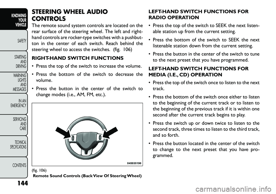
The remote sound system controls are located on the
rear surface of the steering wheel. The left and right-
hand controls are rocker-type switches with a pushbut-
ton in the center of each switch. Reach behind the
steering wheel to access the switches. (fig. 106)
RIGHT-HAND SWITCH FUNCTIONS
Press the top of the switch to increase the volume.
Press the bottom of the switch to decrease thevolume.
Press the button in the center of the switch to change modes (i.e., AM, FM, etc.). LEFT-HAND SWITCH FUNCTIONS FOR
RADIO OPERATION
Press the top of the switch to SEEK the next listen-
able station up from the current setting.
Press the bottom of the switch to SEEK the next listenable station down from the current setting.
Press the button in the center of the switch to tune to the next preset that you have programmed.
LEFT-HAND SWITCH FUNCTIONS FOR
MEDIA (I.E., CD) OPERATION
Press the top of the switch once to listen to the next track.
Press the bottom of the switch once either to listen to the beginning of the current track or to listen to
the beginning of the previous track if it is within one
second after the current track begins to play.
Press the switch up or down twice to listen to the second track, three times to listen to the third track,
and so forth.
Press the button located in the center of the switch to change to the next preset that you have pro-
grammed.(fig. 106)Remote Sound Controls (Back View Of Steering Wheel)
144
KNOWING YOUR
VEHICLE
SAFETY
S
TARTING AND
DRIVING
WARNING LIGHTSAND
MESSAGES
IN AN
EMERGENCY
SERVICING AND
CARETECHNICAL
SPECIFICATIONSCONTENTS
Page 172 of 352
SAFETY
OCCUPANT RESTRAINTS
Some of the most important safety features in your
vehicle are the restraint systems:
Three-point lap and shoulder belts for all seating positions
Advanced Front Air Bags for driver and front passen- ger
Supplemental Active Head Restraints (AHR) located on top of the front seats (integrated into the head
restraint) (for versions/markets, where provided)
Supplemental Side Air Bag Inflatable Curtains (SABIC) that span the front, second, and third row
seating for the driver and passengers seated next to
a window
Supplemental Seat-Mounted Side Air Bags
An energy-absorbing steering column and steering wheel
Knee bolsters/blockers for front seat occupants
Front seat belts incorporate pretensioners that may enhance occupant protection by managing occupant
energy during an impact event
If you will be carrying children too small for adult-sized
seat belts, the seat belts or ISOFIX feature also can be used to hold infant and child restraint systems. For
more information, refer to ISOFIX — Child Seat An-
chorage System.
NOTE:
The Advanced Front Air Bags have a multi-
stage inflator design. This allows the air bag to have
different rates of inflation based on several factors,
including the severity and type of collision.
Please pay close attention to the information in this
section. It tells you how to use your restraint system
properly, to keep you and your passengers as safe as
possible.
WARNING!
In a collision, you and your passengers
can
suffer much greater injuries if you
are not properly buckled up. You can strike the
interior of your vehicle or other passengers, or
you can be thrown out of the vehicle. Always be
sure you and others in your vehicle are buckled
up properly.
Buckle up even though you are an excellent driver, even
on short trips. Someone on the road may be a poor
driver and cause a collision that includes you. This can
happen far away from home or on your own street.
166
KNOWING YOUR
VEHICLE
SAFETY
STARTING AND
DRIVING
W
ARNING LIGHTS AND
MESSAGES
IN AN
EMERGENCY
SERVICING AND
CARETECHNICAL
SPECIFICATIONSCONTENTS
Page 193 of 352
NOTE:
Ensure that the tether strap does not slip into theopening between the seatbacks as you remove slack
in the strap.
When using the ISOFIX attaching system to install a child restraint, please ensure that all seat belts not
being used for occupant restraints are stowed and
out of reach of children. Remind all children in the
vehicle that the seat belts are not toys and that they
should not play with them. In addition, never leave
unattended children in the vehicle.
WARNING!
Improper installation of a child restraint
t
o the ISOFIX anchorages can lead to
failure of an infant or child restraint . The child
could be badly injured or killed. Follow the manu-
facturer's directions exactly when installing an
infant or child restraint .
SUPPLEMENTAL RESTRAINT SYSTEM
(SRS) — AIR BAGS
This vehicle has Advanced Front Air Bags for both the
driver and front passenger as a supplement to the seat
belt restraint systems. The driver's Advanced Front Air
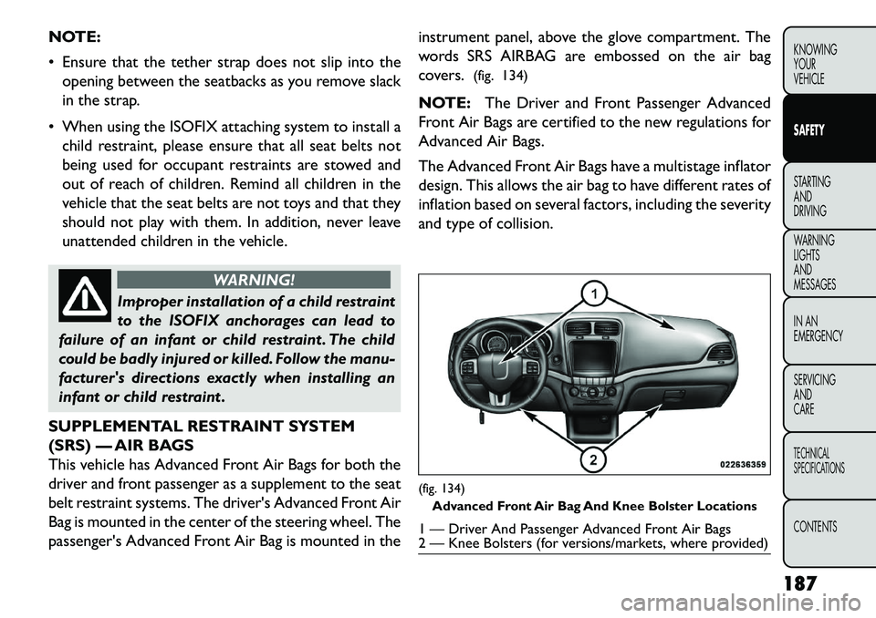
Bag is mounted in the center of the steering wheel. The
passenger's Advanced Front Air Bag is mounted in the instrument panel, above the glove compartment. The
words SRS AIRBAG are embossed on the air bag
covers.
(fig. 134)
NOTE: The Driver and Front Passenger Advanced
Front Air Bags are certified to the new regulations for
Advanced Air Bags.
The Advanced Front Air Bags have a multistage inflator
design. This allows the air bag to have different rates of
inflation based on several factors, including the severity
and type of collision.
(fig. 134) Advanced Front Air Bag And Knee Bolster Locations1 — Driver And Passenger Advanced Front Air Bags
2 — Knee Bolsters (for versions/markets, where provided)
187
KNOWING
YOUR
VEHICLE
SAFETY
STARTING
AND
DRIVING
W
ARNING
LIGHTS
AND
MESSAGES
IN AN
EMERGENCY
SERVICING
AND
CARETECHNICAL
SPECIFICATIONSCONTENTS
Page 194 of 352
This vehicle may be equipped with a driver and/or front
passenger seat belt buckle switch that detects whether
the driver or front passenger seat belt is fastened. The
seat belt buckle switch may adjust the inflation rate of
the Advanced Front Air Bags.
This vehicle is equipped with Supplemental Side Air Bag
Inflatable Curtains (SABIC) to protect the driver, front,
and rear passengers sitting next to a window. The
SABIC air bags are located above the side windows and
their covers are also labeled: SRS AIRBAG.
This vehicle is equipped with Supplemental Seat-
Mounted Side Air Bags (SAB). The SABs are marked
with an air bag label sewn into the outboard side of the
front seats.
NOTE:
Air Bag covers may not be obvious in the interiortrim, but they will open during air bag deployment.
After any accident, the vehicle should be taken to an authorized dealer immediately.
Air Bag System Components
Your vehicle may be equipped with the following air bag
system components:
Occupant Restraint Controller (ORC)
Air Bag Warning Light
Steering Wheel and Column Instrument Panel
Knee Impact Bolster
Driver Advanced Front Air Bag
Passenger Advanced Front Air Bag
Supplemental Seat-Mounted Side Air Bags (SAB)
Supplemental Side Air Bag Inflatable Curtains
(SABIC)
Front and Side Impact Sensors
Front Seat Belt Pretensioners
Seat Belt Buckle Switch
ADVANCED FRONT AIR BAG FEATURES
The Advanced Front Air Bag system has multistage
driver and front passenger air bags. This system pro-
vides output appropriate to the severity and type of
collision as determined by the Occupant Restraint
Controller (ORC), which may receive information
from the front impact sensors.
The first stage inflator is triggered immediately during
an impact that requires air bag deployment. This low
output is used in less severe collisions. A higher energy
output is used for more severe collisions.
188
KNOWING YOUR
VEHICLE
SAFETY
STARTING AND
DRIVING
W
ARNING LIGHTS AND
MESSAGES
IN AN
EMERGENCY
SERVICING AND
CARETECHNICAL
SPECIFICATIONSCONTENTS
Page 198 of 352
If the air bag system in this vehicle needs to be modified
to accommodate a disabled person, contact the Cus-
tomer Center. Phone numbers are provided under "If
You Need Assistance".
WARNING!
R
elying on the air bags alone could
lead to more severe injuries in a collision.
The air bags work with your seat belt to restrain
you properly. In some collisions, the air bags
won't deploy at all. Always wear your seat belts
even though you have air bags.
Being too close to the steering wheel or instru-
ment panel during Advanced Front Air Bag de-
ployment could cause serious injury, including
death. Air Bags need room to inflate. Sit back,
comfortably extending your arms to reach the
steering wheel or instrument panel.
Side air bags also need room to inflate. Do not
lean against the door or window. Sit upright in
the center of the seat .
Air Bag Deployment Sensors And Controls
Occupant Restraint Controller (ORC)
The ORC is part of a regulated safety system required
for this vehicle. The ORC determines if deployment of the front and/or
side air bags in a frontal or side collision is required.
Based on the impact sensor's signals, a central elec-
tronic ORC deploys the Advanced Front Air Bags,
SABIC air bags, Supplemental Seat-Mounted Side Air
Bags, Supplemental Driver Side Knee Air Bag, and front
seat belt pretensioners, as required, depending on
several factors, including the severity and type of im-
pact.
The Advanced Front Air Bags and Supplemental Driver
Side Knee Air Bag are designed to provide additional
protection by supplementing the seat belts in certain
frontal collisions depending on several factors, includ-
ing the severity and type of collision. Advanced Front
Air Bags are not expected to reduce the risk of injury in
rear, side, or rollover collisions.
The Advanced Front Air Bags and Supplemental Driver
Side Knee Air Bag will not deploy in all frontal colli-
sions, including some that may produce substantial
vehicle damage — for example, some pole collisions,
truck underrides, and angle offset collisions. On the
other hand, depending on the type and location of
impact, Advanced Front Air Bags may deploy in crashes
with little vehicle front-end damage but that produce a
severe initial deceleration.
192
KNOWING YOUR
VEHICLE
SAFETY
STARTING AND
DRIVING
W
ARNING LIGHTS AND
MESSAGES
IN AN
EMERGENCY
SERVICING AND
CARETECHNICAL
SPECIFICATIONSCONTENTS